CN115615552B - Method and device for automatically detecting color of keycap on line - Google Patents
Method and device for automatically detecting color of keycap on line Download PDFInfo
- Publication number
- CN115615552B CN115615552B CN202211621485.7A CN202211621485A CN115615552B CN 115615552 B CN115615552 B CN 115615552B CN 202211621485 A CN202211621485 A CN 202211621485A CN 115615552 B CN115615552 B CN 115615552B
- Authority
- CN
- China
- Prior art keywords
- value
- keycap
- color
- module
- photographing
- Prior art date
- Legal status (The legal status is an assumption and is not a legal conclusion. Google has not performed a legal analysis and makes no representation as to the accuracy of the status listed.)
- Active
Links
- 238000000034 method Methods 0.000 title claims abstract description 26
- 238000004364 calculation method Methods 0.000 claims abstract description 8
- 230000007246 mechanism Effects 0.000 claims description 76
- 238000012545 processing Methods 0.000 claims description 28
- 238000009826 distribution Methods 0.000 claims description 13
- 238000012360 testing method Methods 0.000 claims description 10
- 230000000903 blocking effect Effects 0.000 claims description 6
- 238000007418 data mining Methods 0.000 claims description 3
- 230000007723 transport mechanism Effects 0.000 claims description 3
- 238000003384 imaging method Methods 0.000 claims 2
- 238000004519 manufacturing process Methods 0.000 abstract description 11
- 238000001514 detection method Methods 0.000 abstract description 5
- 238000011179 visual inspection Methods 0.000 abstract description 3
- 239000000047 product Substances 0.000 description 18
- 238000010586 diagram Methods 0.000 description 9
- 239000003086 colorant Substances 0.000 description 6
- 239000003973 paint Substances 0.000 description 6
- 238000007599 discharging Methods 0.000 description 4
- 230000004075 alteration Effects 0.000 description 3
- 238000007689 inspection Methods 0.000 description 3
- 238000005507 spraying Methods 0.000 description 3
- 230000000007 visual effect Effects 0.000 description 3
- 238000006467 substitution reaction Methods 0.000 description 2
- 241001292396 Cirrhitidae Species 0.000 description 1
- 230000000694 effects Effects 0.000 description 1
- 238000011156 evaluation Methods 0.000 description 1
- 238000009776 industrial production Methods 0.000 description 1
- 230000007935 neutral effect Effects 0.000 description 1
- 238000007591 painting process Methods 0.000 description 1
- 239000000049 pigment Substances 0.000 description 1
- 238000012805 post-processing Methods 0.000 description 1
- 238000013441 quality evaluation Methods 0.000 description 1
- 230000011218 segmentation Effects 0.000 description 1
- 238000003860 storage Methods 0.000 description 1
- 239000013589 supplement Substances 0.000 description 1
Images


Classifications
-
- G—PHYSICS
- G01—MEASURING; TESTING
- G01J—MEASUREMENT OF INTENSITY, VELOCITY, SPECTRAL CONTENT, POLARISATION, PHASE OR PULSE CHARACTERISTICS OF INFRARED, VISIBLE OR ULTRAVIOLET LIGHT; COLORIMETRY; RADIATION PYROMETRY
- G01J3/00—Spectrometry; Spectrophotometry; Monochromators; Measuring colours
- G01J3/46—Measurement of colour; Colour measuring devices, e.g. colorimeters
- G01J3/50—Measurement of colour; Colour measuring devices, e.g. colorimeters using electric radiation detectors
Landscapes
- Physics & Mathematics (AREA)
- Spectroscopy & Molecular Physics (AREA)
- General Physics & Mathematics (AREA)
- Spectrometry And Color Measurement (AREA)
Abstract
The invention discloses a method and a device for automatically detecting the color of a keycap on line, wherein the method is used for detecting the keycap in Basalt color or Black color and comprises the following steps: setting a safety threshold value; obtaining a comparison value of the color of the keycap to be detected, wherein the calculation mode of the comparison value Realvalue1 is Realvalue1= blue color value-gray color value, and the calculation mode of the gray color value is as follows: gray value = R0.299 + G0.587 + B0.114, wherein R, G, B are the R value, G value and B value of the keycap respectively; if the comparison value of the keycap is larger than the safety threshold value, the keycap is in Basalt color, and if the comparison value of the keycap is smaller than the safety threshold value, the keycap is in Black color. The method and the device for automatically detecting the color of the keycap on line provided by the invention can realize the automatic detection of the color of the keycap on line, do not need manual visual inspection, and have high production efficiency and high accuracy.
Description
Technical Field
The invention relates to the technical field of keyboard processing equipment, in particular to a method and a device for automatically detecting the color of a keycap on line.
Background
With the diversification and appearance individuality requirements of customers on products, the products have different color types and higher single color quality requirements. However, the common products have different colors in the same area, and some colors have slight difference and some colors have serious difference.
The problem of chromatic aberration is a common problem in painted products, and chromatic aberration is troublesome once occurring, can be well treated at a great expense, and has reduced customer satisfaction. The reasons for the color difference include the reasons of the painting process and the reasons of the manufacturing process. The reason of the paint spraying process is as follows: the paint spraying film layer is thin and thick, and pigment on the surface of the paint film is unevenly distributed due to different baking times, so that the problem of paint color difference is caused. The reason of the manufacturing process is as follows: a keyboard with 78 single keycaps each of which is an independent individual can cause the problem of mixing keys of different paint products due to manual key supplement and key replacement after paint spraying.
For the problem of chromatic aberration, inspection is performed manually at present, but the manual inspection has a great risk. This is because the visual judgment of the difference between two colors by manual inspection is mainly two visual evaluations, i.e. perceptibility and acceptability, and visual comparison and judgment have greater subjectivity and variability, and are not suitable for direct use as the basis for color quality evaluation in industrial production.
The foregoing description is provided for general background information and does not necessarily constitute prior art.
Disclosure of Invention
The invention aims to provide a method and a device for automatically detecting the color of a keycap on line, which are used for replacing manual detection and have high production efficiency and high accuracy.
The invention provides a method for automatically detecting the color of a keycap on line, which is used for detecting the keycap in Basalt color or Black color and comprises the following steps: setting a safety threshold value; obtaining a comparison value of the color of the keycap to be detected, wherein the calculation mode of the comparison value Realvalue1 is Realvalue1= blue color value-gray color value, and the calculation mode of the gray color value is as follows: gray value = R0.299 + G0.587 + B0.114, wherein R, G, B are the R value, G value and B value of the keycap respectively; and if the comparison value of the keycap is greater than the safety threshold value, the keycap is in Basalt color, and if the comparison value of the keycap is less than the safety threshold value, the keycap is in Black color.
Further, the setting method of the safety threshold comprises the following steps: testing a large number of Basalt color key caps and Black color key caps, and collecting data; reading the R value, the G value and the B value of each keycap through machine vision software; calculating the gray value and the comparison value Realvalue1 of each keycap according to the R value, the G value and the B value of each keycap; and setting the safety threshold value according to the distribution of the comparison values of the Basalt color key caps and the Black color key caps.
Further, the setting the security threshold according to the distribution of the comparison values of the Basalt color key caps and the Black color key caps comprises: directly obtained by data mining tool software.
Further, the method for setting the safety threshold further includes: before testing a large number of Basalt color key caps and Black color key caps, setting a preliminary safety threshold value by using experience or a small number of test results; the safety threshold value is set according to the distribution of the comparison values of the Basalt color key caps and the Black color key caps as follows: and finely adjusting the preliminary safety threshold value according to the distribution of the comparison values of the Basalt color key caps and the Black color key caps, and taking the safety threshold value obtained according to the distribution of the comparison values of the Basalt color key caps and the Black color key caps as a final safety threshold value.
The invention also provides a device for automatically detecting the color of the keycap on line, which is used for detecting the keycap in Basalt color or Black color and comprises a product conveying module, a photographing module and a data processing module; the product conveying module is used for conveying the keycaps to be detected; the photographing module is used for photographing the keycaps conveyed to the photographing position by the product conveying module; the data processing module is used for carrying out data processing on the photo shot by the photographing module, and the data processing comprises the following steps: reading the R value, G value and B value of the keycap; calculating a gray value and a comparison value Realvalue1 according to the R value, the G value and the B value of the keycap, wherein the gray value = R0.299 + G0.587 + B0.114, R, G, B are the R value, the G value and the B value of the keycap respectively, and Realvalue1= blue value-gray value; if the comparison value of the keycap is greater than the preset safety threshold value, the keycap is in Basalt color, and if the comparison value of the keycap is less than the preset safety threshold value, the keycap is in Black color.
Further, the product conveying module comprises a longitudinal conveying mechanism and a transverse moving mechanism, the longitudinal conveying mechanism is used for conveying the keycaps from the feeding end to the discharging end through the middle position, the transverse moving mechanism is used for driving the longitudinal conveying mechanism to move between a first position and a second position after the keycaps reach the middle position, and the photographing module is located on one side of the longitudinal conveying mechanism at the first position; and at the second position, the longitudinal conveying mechanism is positioned under the photographing module, so that the keycap reaches the photographing position.
And further, the key cap further comprises a stopping jacking module, wherein the stopping jacking module is positioned below the longitudinal conveying mechanism and used for stopping the longitudinal conveying mechanism when the key cap reaches the middle position.
Further, the module of shooing includes fixed bolster, light source, industry camera, the light source is located the fixed bolster below, the fixed bolster is equipped with the through-hole, the industry camera is located the through-hole top is used for right the key cap of through-hole below shoots.
Further, the product conveying module comprises a longitudinal conveying mechanism and a transverse moving mechanism, the longitudinal conveying mechanism is used for conveying the keycaps from the feeding end to the discharging end through the middle position, the transverse moving mechanism is used for driving the longitudinal conveying mechanism to move between a first position and a second position after the keycaps reach the middle position, and the photographing module is located on one side of the longitudinal conveying mechanism at the first position; in the second position, the longitudinal conveying mechanism is positioned right below the photographing module, so that the keycap reaches the photographing position; the device further comprises a stopping jacking module, wherein the stopping jacking module is positioned below the longitudinal conveying mechanism and used for stopping the longitudinal conveying mechanism when the keycap reaches the middle position; when the keycap moves from the feeding end to the middle position through the longitudinal conveying mechanism, the blocking and stopping jacking module blocks and stops the longitudinal conveying mechanism; then the transverse moving mechanism drives the longitudinal conveying mechanism to move from a first position to a second position, the photographing module is located on one side of the longitudinal conveying mechanism at the first position, and the longitudinal conveying mechanism is located right below the photographing module at the second position so that the keycap reaches the photographing position; then the key cap is photographed by the photographing module; after the picture is taken, the picture in the photographing module is transmitted to the data processing module for data processing, and the transverse moving mechanism drives the longitudinal conveying mechanism to move from the second position to the first position; and the blocking and stopping jacking module retracts to enable the longitudinal conveying mechanism to continuously convey the keycaps to the discharge end.
Further, the data processing module comprises a computer, a program stored in the computer, a programmable logic controller and a display, the programmable logic controller is connected with the computer and the photographing module and is used for controlling the photographing module according to an instruction set by the program to enable the photographing module to perform photographing operation and transmit photos, the computer is used for performing data processing on the photos, and the display is connected with the computer and is used for displaying data processing results.
According to the method and the device for automatically detecting the color of the keycap on line, the keycap is judged to be Basalt color or Black color by introducing the comparison value Realvalue1= blue value-grey value and comparing the comparison value of the keycap to be detected with the preset safety threshold value, so that the color of the keycap can be automatically detected on line, manual visual inspection is not needed, the production efficiency is high, and the accuracy is high.
Drawings
Fig. 1 is a schematic diagram of a Basalt color keycap according to the method and the device for automatically detecting the color of the keycap on line in the embodiment of the invention.
FIG. 2 is a schematic diagram of a Black keycap according to the embodiment of the invention.
FIG. 3 is a distribution diagram of comparison values corresponding to key caps of some keys tested in the method and apparatus for on-line automatic detection of color of key caps according to the embodiment of the present invention.
FIG. 4 is a block diagram of an apparatus for on-line automatic detection of keycap color according to an embodiment of the present invention.
FIG. 5 is an overall schematic diagram of an apparatus for automatically detecting a color of a keycap on line according to an embodiment of the present invention.
FIG. 6 is a schematic diagram of the internal main mechanism of the device for automatically detecting the color of the keycap on line shown in FIG. 5.
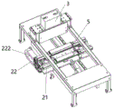
Fig. 7 is a schematic diagram of a product conveying module, a stop jacking module and related elements in the device for automatically detecting the color of a keycap on line shown in fig. 6.
FIG. 8 is a schematic diagram of a photographing module in the device for automatically detecting the color of the key cap on line shown in FIG. 6.
FIG. 9 is a schematic view showing an operation flow of the device for automatically detecting the color of the keycap on line shown in FIG. 5.
Detailed Description
The following detailed description of embodiments of the present invention is provided in connection with the accompanying drawings and examples. The following examples are intended to illustrate the invention but are not intended to limit the scope of the invention.
In this embodiment, the method for automatically detecting the color of the key cap on line is used to detect that the key cap is Basalt (Basalt gray) (as shown in fig. 1) or Black (Black) (as shown in fig. 2), and includes: setting a safety threshold value; obtaining a comparison value of the color of the keycap to be detected, wherein the calculation mode of the comparison value Realvalue1 is Realvalue1= blue value-gray value, and the calculation mode of the gray value is as follows: gray value = R0.299 + G0.587 + B0.114, wherein R, G, B are R value, G value and B value of the key cap respectively; if the comparison value of the keycap is greater than the safety threshold value, the keycap is in Basalt color, and if the comparison value of the keycap is less than the safety threshold value, the keycap is in Black color. In this embodiment, the safety threshold is a value between 63 and 65 (as shown in fig. 3, the upper horizontal line indicates a Realvalue1 value of 65, and the lower horizontal line indicates a Realvalue1 value of 62).
The comparison value Realvalue1= blue value-gray value enables a stable difference between Basalt and Black colors to be formed. Fig. 3 shows the comparison value corresponding to each key cap, for example, in fig. 3, the point above the upper horizontal line is Basalt color, the point below the lower horizontal line is Black color, and the comparison values of the two colors form an obvious and stable difference, so that the comparison value Realvalue1= blue color value-gray color value is adopted, and the comparison value of the key cap to be detected is compared with the preset safety threshold value to judge that the key cap is Basalt color or Black color, thereby not only realizing on-line automatic detection of the key cap color without manual visual inspection, but also having high production efficiency and high accuracy.
In this embodiment, the method for setting the safety threshold includes: testing a large number of Basalt color key caps and Black color key caps, and collecting data; reading R value, G value and B value of each keycap through machine vision software (such as MVTec HALCON); calculating the gray value and the comparison value Realvalue1 of each keycap according to the R value, the G value and the B value of each keycap; and setting a safety threshold value according to the distribution of the comparison values of the Basalt color key caps and the Black color key caps. The mode of setting the safety threshold according to the distribution of the comparison values can be directly obtained by data mining tool software (can be combined with manual setting), for example, a segmentation line is obtained by adding in a scatter diagram. Of course, in other embodiments, the safety threshold may be set in other manners, for example, the safety threshold is set by using experience or a small amount of test results, and then the setting method is used to finely adjust the safety threshold after a large amount of data is accumulated in the production process, so as to set a more accurate final safety threshold.
As shown in fig. 4 to 9, the embodiment further provides a device for automatically detecting the color of the keycap on line, which is used for detecting that the keycap is Basalt color or Black color, and includes a rack 1, and a product conveying module 2, a photographing module 3, a data processing module, and a blocking and stopping jacking module 5 which are mounted on the rack 1.
The product conveying module 2 is used for conveying keycaps 6 to be detected. As shown in fig. 6 and 7, in the present embodiment, the product conveying module 2 includes a longitudinal conveying mechanism 21 and a transverse moving mechanism 22. The longitudinal conveying mechanism 21 is used for conveying the keycaps 6 (each keycap is placed on a tray similar to a keyboard) from the feeding end to the discharging end through the middle position, and a production line mechanism can be adopted. The transverse moving mechanism 22 is used for driving the longitudinal conveying mechanism 21 to move between the first position and the second position after the keycap 6 reaches the middle position, and may include a motor (not numbered) and a conveying belt 222, and the longitudinal conveying mechanism 21 is fixed on the conveying belt 222. In the first position, the photographing module 3 is positioned at one side of the longitudinal conveying mechanism 21; in the second position, the longitudinal conveying mechanism 21 is positioned right below the photographing module 3, so that the keycap 6 reaches the photographing position. Of course, in other embodiments, the traversing mechanism may not be provided, and the photographing may be performed directly at the intermediate position. But the arrangement of the transverse moving mechanism is more convenient for the arrangement of each module. As shown in fig. 7, the product conveying module may further include a scanning gun 23 disposed above the longitudinal conveying mechanism for scanning the product number of the keycap for storage and subsequent tracing.
The photographing module 3 is used for photographing the keycap 6 conveyed to the photographing position by the product conveying module 2. As shown in fig. 8, in the present embodiment, the photographing module 3 includes a fixing bracket 31, a light source 32, and an industrial camera 33. The light source 32 is located below the fixing bracket 31. The fixed support 31 is provided with a through hole 311, and the industrial camera 33 is located above the through hole 311 and used for taking a picture of the keycap 6 below the through hole 311.
As shown in fig. 7, in the present embodiment, the stopping and jacking module 5 is located below the longitudinal conveying mechanism 21 and is used for stopping the longitudinal conveying mechanism 21 when the keycap 6 reaches the middle position. The stop jacking module 5 comprises a stop block 51 and a jacking mechanism 52. The stop block 51 is located forward of the neutral position to stop the longitudinal transport mechanism from further forward movement. The jacking mechanism 52 is connected with the stopping block 51 and is used for driving the stopping block 51 to move up and down through jacking and retracting. When the stopping block 51 is positioned at the uppermost end by jacking, the longitudinal conveying mechanism 21 can be stopped to stop the operation of the longitudinal conveying mechanism to drive the keycap to move forwards continuously; and when the stopping block 51 is retracted to be positioned at the lowest end, the longitudinal conveying mechanism 21 is allowed to continue to operate and convey the keycap 6. In other embodiments, a stop jacking module with other structures can be arranged, but the stop jacking module is simple in structure and reliable in operation. The stop of the longitudinal conveying mechanism can be controlled by a program without arranging a stop jacking module, and even the photographing module is not stopped to photograph in the key cap operation process. But set up to keep off jacking module and enable the location more accurate and simple reliable, the effect of shooing is also better.
The data processing module is used for carrying out data processing on the photo shot by the photographing module, and the data processing comprises the following steps: reading the R value, the G value and the B value of the keycap; calculating a gray value and a comparison value Realvalue1 according to the R value, the G value and the B value of the keycap, wherein the gray value = R0.299 + G0.587 + B0.114, R, G, B are the R value, the G value and the B value of the keycap respectively, and Realvalue1= blue value-gray value; if the comparison value of the keycap is greater than the preset safety threshold value, the keycap is in Basalt color, and if the comparison value of the keycap is less than the preset safety threshold value, the keycap is in Black color.
As shown in fig. 4 and 5, in the present embodiment, the data processing module includes a computer 41, a program stored in the computer 41, a Programmable Logic Controller (PLC) 42, and a display 43. The programmable logic controller 42 is connected to the computer 41 and the photographing module 3, and is configured to control the photographing module 3 according to a command set by a program, so that the photographing module 3 performs a photographing operation and transmits a photo. The computer 41 is used to perform the above-described data processing on the photograph. The display 43 is connected to the computer 41 for displaying the data processing result.
As shown in fig. 9, the operation flow of the device for automatically detecting the color of the keycap on line in the embodiment is as follows:
when the keycap 6 flowing in from the previous process moves to the middle position (as S1 in FIG. 9) from the feeding end through the longitudinal conveying mechanism 21, the blocking and stopping jacking module 5 blocks and stops the longitudinal conveying mechanism 21 (as S2 in FIG. 9);
then the transverse moving mechanism 22 drives the longitudinal conveying mechanism 21 to move from the first position to the second position (as shown in S3 in fig. 9), so that the keycap 6 reaches the photographing position;
then the photographing module 3 photographs the keycap 6 (as shown in S3 in fig. 9);
after taking a picture, the picture in the photographing module 3 is transmitted to the data processing module for data processing, and the transverse moving mechanism 22 drives the longitudinal conveying mechanism 21 to move from the second position back to the first position (as S4 in fig. 9);
the stopping and jacking module 5 retracts (as shown in S5 in fig. 9), so that the longitudinal conveying mechanism 21 continues to convey the keycap 6 to the discharging end (as shown in S6 in fig. 9), and the keycap flows into the post-processing procedure.
Compared with the prior art, the embodiment has the following advantages:
(1) The color mixing and color difference of the keycap are thoroughly solved, and the risk of color mixing and color difference can be greatly reduced;
(2) Each disc of product data is stored in the computer, and a fool-proof function can be added to avoid leakage risks;
(3) Test data and pictures are stored, and the test condition at that time can be traced;
(4) The production line is more stable in production and can obviously improve the production efficiency.
In this document, the terms "upper", "lower", "front", "rear", "left", "right", "top", "bottom", "inner", "outer", "vertical", "horizontal", and the like indicate orientations or positional relationships based on the orientations or positional relationships shown in the drawings, and are only for the purpose of clarity and convenience of description of the technical solutions, and thus, should not be construed as limiting the present invention.
As used herein, the terms "comprises," "comprising," or any other variation thereof, are intended to cover a non-exclusive inclusion, including not only those elements listed, but also other elements not expressly listed.
The above description is only for the specific embodiments of the present invention, but the scope of the present invention is not limited thereto, and any person skilled in the art can easily conceive of the changes or substitutions within the technical scope of the present invention, and all the changes or substitutions should be covered within the scope of the present invention. Therefore, the protection scope of the present invention shall be subject to the protection scope of the appended claims.
Claims (10)
1. A method for automatically detecting the color of a keycap on line is used for detecting that the keycap is Basalt color or Black color, and is characterized by comprising the following steps: setting a safety threshold value; obtaining a comparison value of the color of the keycap to be detected, wherein the calculation mode of the comparison value Realvalue1 is Realvalue1= blue value-gray value, and the calculation mode of the gray value is as follows: gray value = R0.299 + G0.587 + B0.114, wherein R, G, B are R value, G value and B value of the key cap respectively; if the comparison value of the keycap is larger than the safety threshold value, the keycap is in Basalt color, and if the comparison value of the keycap is smaller than the safety threshold value, the keycap is in Black color.
2. The method as claimed in claim 1, wherein the method for setting the safety threshold comprises: testing a large number of Basalt color key caps and Black color key caps, and collecting data; reading the R value, the G value and the B value of each keycap through machine vision software; calculating a gray value and a comparison value Realvalue1 of each keycap according to the R value, the G value and the B value of each keycap; setting the safety threshold according to the distribution of the comparison values of the Basalt color key caps and the Black color key caps.
3. The method of claim 2, wherein setting the security threshold based on the distribution of the comparison values for the Basalt and Black keycaps comprises: directly obtained by data mining tool software.
4. The method of claim 2, wherein the method for setting the safety threshold further comprises: before testing a large number of Basalt color key caps and Black color key caps, setting a preliminary safety threshold value by using experience or a small number of test results; the safety threshold value is set according to the distribution of the comparison values of the Basalt color key caps and the Black color key caps as follows: and finely adjusting the preliminary safety threshold value according to the distribution of the comparison values of the Basalt color key caps and the Black color key caps, and taking the safety threshold value obtained according to the distribution of the comparison values of the Basalt color key caps and the Black color key caps as a final safety threshold value.
5. A device for automatically detecting the color of a keycap on line is used for detecting the keycap in Basalt color or Black color and is characterized by comprising a product conveying module, a photographing module and a data processing module; the product conveying module is used for conveying the keycaps to be detected; the photographing module is used for photographing the keycaps conveyed to the photographing position by the product conveying module; the data processing module is used for carrying out data processing on the photo shot by the photographing module, and the data processing comprises the following steps: reading the R value, the G value and the B value of the keycap; calculating a gray value and a comparison value Realvalue1 according to the R value, the G value and the B value of the key cap, wherein the gray value = R0.299 + G0.587 + B0.114, R, G, B are the R value, the G value and the B value of the key cap respectively, and Realvalue1= blue value-gray value; if the comparison value of the keycap is greater than the preset safety threshold value, the keycap is in Basalt color, and if the comparison value of the keycap is less than the preset safety threshold value, the keycap is in Black color.
6. The apparatus of claim 5, wherein the product delivery module comprises a longitudinal delivery mechanism for delivering the key cap from the infeed end to the outfeed end through an intermediate position, and a traversing mechanism for moving the longitudinal delivery mechanism between a first position in which the imaging module is positioned to one side of the longitudinal delivery mechanism and a second position after the key cap reaches the intermediate position; and at the second position, the longitudinal conveying mechanism is positioned under the photographing module, so that the keycap reaches the photographing position.
7. The apparatus of claim 6, further comprising a stop jacking module located below the longitudinal transport mechanism for stopping the longitudinal transport mechanism when the key cap reaches the intermediate position.
8. The device of claim 5, wherein the photographing module comprises a fixed support, a light source and an industrial camera, the light source is located below the fixed support, the fixed support is provided with a through hole, and the industrial camera is located above the through hole and is used for photographing the keycap below the through hole.
9. The apparatus of claim 5, wherein the product delivery module comprises a longitudinal delivery mechanism for delivering the key cap from the infeed end to the outfeed end through an intermediate position, and a traversing mechanism for moving the longitudinal delivery mechanism between a first position in which the imaging module is positioned to one side of the longitudinal delivery mechanism and a second position after the key cap reaches the intermediate position; in the second position, the longitudinal conveying mechanism is positioned right below the photographing module, so that the keycap reaches the photographing position; the device further comprises a stopping jacking module, wherein the stopping jacking module is positioned below the longitudinal conveying mechanism and used for stopping the longitudinal conveying mechanism when the keycap reaches the middle position; when the keycap moves from the feeding end to the middle position through the longitudinal conveying mechanism, the blocking and stopping jacking module blocks and stops the longitudinal conveying mechanism; then the transverse moving mechanism drives the longitudinal conveying mechanism to move from a first position to a second position, the photographing module is located on one side of the longitudinal conveying mechanism at the first position, and the longitudinal conveying mechanism is located right below the photographing module at the second position so that the keycap reaches a photographing position; then the key cap is photographed by the photographing module; after the picture is taken, the picture in the photographing module is transmitted to the data processing module for data processing, and the transverse moving mechanism drives the longitudinal conveying mechanism to move from the second position to the first position; and the blocking and stopping jacking module retracts to enable the longitudinal conveying mechanism to continuously convey the keycaps to the discharge end.
10. The device as claimed in any one of claims 5 to 9, wherein the data processing module comprises a computer, a program stored in the computer, a programmable logic controller, and a display, the programmable logic controller is connected to the computer and the photographing module, and is configured to control the photographing module according to an instruction set by the program, so that the photographing module performs photographing operation and transmits a photograph, the computer is configured to perform data processing on the photograph, and the display is connected to the computer and is configured to display a data processing result.
Priority Applications (1)
| Application Number | Priority Date | Filing Date | Title |
|---|---|---|---|
| CN202211621485.7A CN115615552B (en) | 2022-12-16 | 2022-12-16 | Method and device for automatically detecting color of keycap on line |
Applications Claiming Priority (1)
| Application Number | Priority Date | Filing Date | Title |
|---|---|---|---|
| CN202211621485.7A CN115615552B (en) | 2022-12-16 | 2022-12-16 | Method and device for automatically detecting color of keycap on line |
Publications (2)
| Publication Number | Publication Date |
|---|---|
| CN115615552A CN115615552A (en) | 2023-01-17 |
| CN115615552B true CN115615552B (en) | 2023-04-04 |
Family
ID=84879554
Family Applications (1)
| Application Number | Title | Priority Date | Filing Date |
|---|---|---|---|
| CN202211621485.7A Active CN115615552B (en) | 2022-12-16 | 2022-12-16 | Method and device for automatically detecting color of keycap on line |
Country Status (1)
| Country | Link |
|---|---|
| CN (1) | CN115615552B (en) |
Citations (5)
| Publication number | Priority date | Publication date | Assignee | Title |
|---|---|---|---|---|
| US6310969B1 (en) * | 1998-05-28 | 2001-10-30 | Lg Electronics Inc. | Color coordinate space structure and color quantizing and variable gray area designating method therein |
| JP2008092085A (en) * | 2006-09-29 | 2008-04-17 | Nec Personal Products Co Ltd | Chroma key detection range adjusting method and information processor |
| CN104484659A (en) * | 2014-12-30 | 2015-04-01 | 南京巨鲨显示科技有限公司 | Method for automatically identifying and calibrating medical color images and medical gray scale images |
| CN114359196A (en) * | 2021-12-27 | 2022-04-15 | 以萨技术股份有限公司 | Fog detection method and system |
| CN115665565A (en) * | 2022-10-25 | 2023-01-31 | 云南省烟草烟叶公司 | Online tobacco leaf image color correction method, system and device |
Family Cites Families (1)
| Publication number | Priority date | Publication date | Assignee | Title |
|---|---|---|---|---|
| US20040160616A1 (en) * | 2003-02-18 | 2004-08-19 | Match Lab, Inc. | Black and white image color mark removal |
-
2022
- 2022-12-16 CN CN202211621485.7A patent/CN115615552B/en active Active
Patent Citations (5)
| Publication number | Priority date | Publication date | Assignee | Title |
|---|---|---|---|---|
| US6310969B1 (en) * | 1998-05-28 | 2001-10-30 | Lg Electronics Inc. | Color coordinate space structure and color quantizing and variable gray area designating method therein |
| JP2008092085A (en) * | 2006-09-29 | 2008-04-17 | Nec Personal Products Co Ltd | Chroma key detection range adjusting method and information processor |
| CN104484659A (en) * | 2014-12-30 | 2015-04-01 | 南京巨鲨显示科技有限公司 | Method for automatically identifying and calibrating medical color images and medical gray scale images |
| CN114359196A (en) * | 2021-12-27 | 2022-04-15 | 以萨技术股份有限公司 | Fog detection method and system |
| CN115665565A (en) * | 2022-10-25 | 2023-01-31 | 云南省烟草烟叶公司 | Online tobacco leaf image color correction method, system and device |
Also Published As
| Publication number | Publication date |
|---|---|
| CN115615552A (en) | 2023-01-17 |
Similar Documents
| Publication | Publication Date | Title |
|---|---|---|
| US9757772B2 (en) | Inspection system | |
| US11014376B2 (en) | Apparatus and method for controlling direct printing machines | |
| CN111610190B (en) | Appearance inspection device for household appliances | |
| CN111999308A (en) | A control method, control device and control system for defect detection | |
| CN109142381B (en) | High-speed visual detection and identification equipment | |
| CN105372252A (en) | Detecting system and method based on machine vision | |
| CN110530892A (en) | A kind of workpiece flaw disc type check machine more regarded based on polychromatic source general-using type | |
| CN110126467A (en) | A kind of fusion black liquid detection device and method suitable for large-area substrates printing | |
| EP3800054A1 (en) | Solution application apparatus and a tablet printing apparatus | |
| CN204142648U (en) | A kind of detection system based on machine vision | |
| CN106767423A (en) | Automatic Visual Inspection instrument | |
| CN109807076A (en) | Double-coated pressure-sensitive glue automatic optical detection method and its equipment | |
| CN109647727A (en) | A kind of OLED display module vision-based detection assembly line | |
| CN105352969A (en) | Edible oil product color and luster, transparency and impurity detecting device | |
| CN106290175B (en) | Conveyer belt opens and stops device and printed matter visual detection equipment | |
| CN115615552B (en) | Method and device for automatically detecting color of keycap on line | |
| US20240131559A1 (en) | Inspection system | |
| CN113030095A (en) | Polaroid appearance defect detecting system | |
| CN206670551U (en) | Automatic Visual Inspection instrument | |
| CN106573478A (en) | Device and method for printing containers having error detection | |
| WO2017049863A1 (en) | Liquid crystal one drop filling system and control method | |
| CN113020000A (en) | Detection system for air conditioner | |
| CA3128666A1 (en) | Repairing an outer surface of a glass product | |
| CN111638153A (en) | Sampling inspection device suitable for energy-saving production line of display screen | |
| KR20110013085A (en) | Polyester film appearance inspection device for solar cell and inspection method |
Legal Events
| Date | Code | Title | Description |
|---|---|---|---|
| PB01 | Publication | ||
| PB01 | Publication | ||
| SE01 | Entry into force of request for substantive examination | ||
| SE01 | Entry into force of request for substantive examination | ||
| GR01 | Patent grant | ||
| GR01 | Patent grant |