CN115613529A - Layout structure of a high head ecological flow discharge tunnel - Google Patents
Layout structure of a high head ecological flow discharge tunnel Download PDFInfo
- Publication number
- CN115613529A CN115613529A CN202211337049.7A CN202211337049A CN115613529A CN 115613529 A CN115613529 A CN 115613529A CN 202211337049 A CN202211337049 A CN 202211337049A CN 115613529 A CN115613529 A CN 115613529A
- Authority
- CN
- China
- Prior art keywords
- tunnel
- ecological
- water
- flow
- head
- Prior art date
- Legal status (The legal status is an assumption and is not a legal conclusion. Google has not performed a legal analysis and makes no representation as to the accuracy of the status listed.)
- Pending
Links
Images


Classifications
-
- E—FIXED CONSTRUCTIONS
- E02—HYDRAULIC ENGINEERING; FOUNDATIONS; SOIL SHIFTING
- E02B—HYDRAULIC ENGINEERING
- E02B9/00—Water-power plants; Layout, construction or equipment, methods of, or apparatus for, making same
- E02B9/02—Water-ways
- E02B9/06—Pressure galleries or pressure conduits; Galleries specially adapted to house pressure conduits; Means specially adapted for use therewith, e.g. housings, valves, gates
-
- E—FIXED CONSTRUCTIONS
- E02—HYDRAULIC ENGINEERING; FOUNDATIONS; SOIL SHIFTING
- E02B—HYDRAULIC ENGINEERING
- E02B8/00—Details of barrages or weirs ; Energy dissipating devices carried by lock or dry-dock gates
- E02B8/06—Spillways; Devices for dissipation of energy, e.g. for reducing eddies also for lock or dry-dock gates
-
- Y—GENERAL TAGGING OF NEW TECHNOLOGICAL DEVELOPMENTS; GENERAL TAGGING OF CROSS-SECTIONAL TECHNOLOGIES SPANNING OVER SEVERAL SECTIONS OF THE IPC; TECHNICAL SUBJECTS COVERED BY FORMER USPC CROSS-REFERENCE ART COLLECTIONS [XRACs] AND DIGESTS
- Y02—TECHNOLOGIES OR APPLICATIONS FOR MITIGATION OR ADAPTATION AGAINST CLIMATE CHANGE
- Y02E—REDUCTION OF GREENHOUSE GAS [GHG] EMISSIONS, RELATED TO ENERGY GENERATION, TRANSMISSION OR DISTRIBUTION
- Y02E10/00—Energy generation through renewable energy sources
- Y02E10/20—Hydro energy
Landscapes
- Engineering & Computer Science (AREA)
- General Engineering & Computer Science (AREA)
- Mechanical Engineering (AREA)
- Civil Engineering (AREA)
- Structural Engineering (AREA)
- Sewage (AREA)
Abstract
本发明公开了一种高水头生态流量泄水洞的布置结构,包括有发电分层取水进水口,发电分层取水进水口的侧边墩上预留开孔,该预留开孔通过有压隧洞连接至生态流量闸阀控制室,生态流量闸阀控制室的出水流入消力池,消力池的出水口经第二次消能结构与低高程导流洞堵头段之后的隧洞连通。本发明在发电分层取水进水口后的侧边墩上预留开孔,再通过有压隧洞接至生态流量闸阀控制室,闸阀控制室出来的水流经过消力池进行第一次消能,消力池中的水流可分别采用竖井旋流消能工、或斜井台阶消能工、亦或竖井和水平消力墩消能工联合的三种实施方案之一进行第二次消能,水流降落至低高程导流洞堵头段之后的隧洞内,再排向下游河道,满足下游生态流量泄放要求。

The invention discloses an arrangement structure of a high water head ecological flow discharge tunnel, which includes a power generation layered water intake inlet, and an opening is reserved on the side pier of the power generation layered water intake inlet, and the reserved opening is passed through a pressurized The tunnel is connected to the control room of the ecological flow gate valve, and the outlet water of the control room of the ecological flow gate valve flows into the stilling pool, and the outlet of the stilling pool is connected to the tunnel behind the plug section of the low-elevation diversion tunnel through the second energy dissipation structure. In the present invention, openings are reserved on the side pier behind the water inlet of the stratified water intake for power generation, and then connected to the ecological flow gate valve control room through a pressurized tunnel. The water flow from the gate valve control room passes through the stilling pool for the first energy dissipation. The water flow in the stilling pool can be dissipated for the second time by adopting one of the three implementations of vertical shaft swirl energy dissipator, inclined shaft step energy dissipator, or combination of vertical shaft and horizontal stilling pier energy dissipator, respectively. The water flow falls into the tunnel behind the plug section of the low-elevation diversion tunnel, and then drains to the downstream river channel to meet the downstream ecological flow discharge requirements.
Description
技术领域technical field
本发明涉及一种高水头生态流量泄水洞的布置结构, 属于水电水利工程技术领域。The invention relates to an arrangement structure of a high-head ecological flow discharge tunnel, and belongs to the technical field of hydropower and water conservancy engineering.
背景技术Background technique
在水电水利工程建设中,水库是不可缺少的拦洪蓄水和调节水流的水利工程建筑物,尤其在高坝大库工程中,水库中水体在铅直方向会存在温度和密度梯度,不同深度水体,其水质的水温、溶解氧、浮游生物、浑浊度、二氧化碳等是不同的,从不同深度取水,对生态、农业、水产养殖、人类生活及下游环境带来的影响不同。国家相关法律法规对生态环境保护高度关切,为了保护下游生态环境,或者维持下游生物生存生态平衡,要求在任何时段均要求满足下游生态流量泄放要求。In the construction of hydropower and water conservancy projects, the reservoir is an indispensable hydraulic engineering structure for retaining flood water and regulating water flow. Especially in high dam and large reservoir projects, there will be temperature and density gradients in the water body in the vertical direction in the reservoir. The water quality is different in water temperature, dissolved oxygen, plankton, turbidity, carbon dioxide, etc. Water taken from different depths has different impacts on ecology, agriculture, aquaculture, human life and the downstream environment. Relevant national laws and regulations are highly concerned about the protection of the ecological environment. In order to protect the downstream ecological environment or maintain the ecological balance of the survival of downstream organisms, it is required to meet the downstream ecological flow discharge requirements at any time.
目前,水电站运行期正常情况下,生态流量泄放采用机组发电方式保证下泄流量,但是考虑到在运行过程中存在发生各种事故的可能性,比如电网发生故障,电量不能向外输送,或者机组全部发生事故,不能正常运行时,机组将全面停机,生态流量不能通过机组下放,此时可根据水库在不同运行水位情况下,采用溢洪道、泄洪洞、放空洞等永久泄水建筑物闸门局开方式进行泄放生态流量,虽然此时能满足生态流量的水量要求,但是不能满足生态用水中分层取水水质的质量要求,同时闸门较长时间的局开也存在安全隐患,尤其针对高坝大库,生态取水面临水头高、生态流量大、水位变幅大等特点,这类问题比较突出,虽然有些工程通过设置单独的生态管道,但是其对活塞阀门和出口泄洪消能防冲要求较高。所以,如何实现随时保质保量地下泄生态流量是解决生态用水安全问题的重点关注对象之一,现有技术还存在不足,有待于进一步完善。At present, under normal conditions during the operation period of hydropower stations, the ecological flow discharge adopts the power generation method of the unit to ensure the discharge flow. When all accidents occur and cannot operate normally, the unit will be fully shut down, and the ecological flow cannot be released through the unit. At this time, according to the different operating water levels of the reservoir, the gates of permanent discharge structures such as spillways, flood tunnels, and emptying tunnels can be used. Although the ecological flow can be discharged in this way, although the water volume requirement of the ecological flow can be met at this time, it cannot meet the quality requirements of the stratified water intake in the ecological water. At the same time, there are potential safety hazards if the gate is opened for a long time, especially for high dams. Ecological water intake is faced with the characteristics of high water head, large ecological flow, and large water level fluctuations. These problems are more prominent. Although some projects have set up separate ecological pipelines, they have higher requirements for piston valves and outlet flood discharge, energy dissipation and anti-scouring. . Therefore, how to realize the release of ecological flow with quality and quantity at any time is one of the key concerns to solve the problem of ecological water safety. There are still deficiencies in the existing technology and need to be further improved.
发明内容Contents of the invention
本发明的目的在于,提供一种高水头生态流量泄水洞的布置结构。该结构利用已有的发电分层取水进水口和低高程导流洞,通过合理的线路布置设计和消能措施,以解决传统技术不能实现在任何时段均能保质保量满足下游生态流量的泄放要求,同时具备适应高坝大库工程中面临的下泄生态用水水头高、生态流量大、水位变幅大等特点。The object of the present invention is to provide an arrangement structure of a high water head ecological flow discharge tunnel. This structure uses the existing stratified water intake and low-elevation diversion tunnels for power generation, and through reasonable line layout design and energy dissipation measures, it solves the problem that traditional technologies cannot meet the downstream ecological flow with quality and quantity at any time. At the same time, it has the characteristics of high water head, large ecological flow, and large water level variation faced in high dam and large reservoir projects.
本发明的技术方案:一种高水头生态流量泄水洞的布置结构,包括有发电分层取水进水口,发电分层取水进水口的侧边墩上预留开孔,该预留开孔通过有压隧洞连接至生态流量闸阀控制室,生态流量闸阀控制室的出水流入消力池,消力池的出水口经第二次消能结构与低高程导流洞堵头段之后的隧洞连通。The technical solution of the present invention: a layout structure of a high-head ecological flow discharge tunnel, including a power generation layered water intake inlet, and openings are reserved on the side pier of the power generation layered water intake inlet, and the reserved openings pass through The pressurized tunnel is connected to the control room of the ecological flow gate valve, and the outlet water of the control room of the ecological flow gate valve flows into the stilling pool, and the outlet of the stilling pool is connected to the tunnel behind the plug section of the low-elevation diversion tunnel through the second energy dissipation structure.
前述的一种高水头生态流量泄水洞的布置结构中,所述第二次消能结构为竖井旋流消能工。In the arrangement structure of the aforementioned high-head ecological flow discharge tunnel, the second energy dissipation structure is a vertical shaft swirling energy dissipation device.
前述的一种高水头生态流量泄水洞的布置结构中,所述第二次消能结构为斜井台阶消能工。In the arrangement structure of the aforementioned high-head ecological flow discharge tunnel, the second energy dissipation structure is an inclined shaft step energy dissipation structure.
前述的一种高水头生态流量泄水洞的布置结构中,所述第二次消能结构为竖井和水平消力墩消能工联合结构,消力池的出水口经竖井与低高程导流洞堵头段之后的隧洞连通,低高程导流洞堵头段之后的隧洞中间隔设置有水平消力墩消能工。In the aforementioned layout structure of a high-head ecological flow discharge tunnel, the second energy-dissipating structure is a combined structure of a vertical shaft and a horizontal stilling pier, and the outlet of the stilling pool passes through the vertical shaft and the low-elevation diversion structure. The tunnel behind the plug section of the tunnel is connected, and the tunnel behind the plug section of the low-elevation diversion tunnel is provided with horizontal stilling piers at intervals.
前述的一种高水头生态流量泄水洞的布置结构中,所述第二次消能结构与低高程导流洞堵头段之间的隧洞中设置有封堵混凝土。In the arrangement structure of the aforementioned high-head ecological flow discharge tunnel, the tunnel between the second energy dissipation structure and the plug section of the low-elevation diversion tunnel is provided with plugging concrete.
前述的一种高水头生态流量泄水洞的布置结构中,所述消力池顶端经通气洞与外部环境导通。In the arrangement structure of the aforementioned high-head ecological flow discharge tunnel, the top of the stilling pool is connected to the external environment through the ventilation hole.
本发明的有益效果:与现有技术相比,本发明在发电分层取水进水口后的侧边墩上预留开孔,再通过有压隧洞接至生态流量闸阀控制室,闸阀控制室出来的水流经过消力池进行第一次消能,闸阀控制室顶部设置通气洞至发电分层取水进水口顶部平台以满足消力池顶部的补排气功能,防止气爆现象对结构产生破坏,消力池中的水流可分别采用竖井旋流消能工、或斜井台阶消能工、亦或竖井和水平消力墩消能工联合的三种实施方案之一进行第二次消能,水流降落至低高程导流洞堵头段之后的隧洞内,再排向下游河道,满足下游生态流量泄放要求。发电分层取水进水口可根据上游不同水位及生态用水水质的要求控制取水区域,闸阀控制室可根据上游不同水位调节闸阀开度控制生态流量的水量大小。Beneficial effects of the present invention: Compared with the prior art, the present invention reserves openings on the side pier behind the water inlet of the stratified water intake for power generation, and then connects to the ecological flow gate valve control room through a pressurized tunnel, and the gate valve control room comes out The water flows through the stilling pool for the first energy dissipation, and the top of the gate valve control room is provided with a ventilation hole to the top platform of the power generation stratified water intake to meet the function of replenishing and exhausting at the top of the stilling pool to prevent the structure from being damaged by the gas explosion. The water flow in the stilling pool can be dissipated for the second time by adopting one of the three implementations of vertical shaft swirl energy dissipator, inclined shaft step energy dissipator, or combination of vertical shaft and horizontal stilling pier energy dissipator, respectively. The water flow falls into the tunnel behind the plug section of the low-elevation diversion tunnel, and then drains to the downstream river channel to meet the downstream ecological flow discharge requirements. The stratified water intake for power generation can control the water intake area according to different upstream water levels and ecological water quality requirements, and the gate valve control room can adjust the gate valve opening to control the water volume of ecological flow according to different upstream water levels.
综合而言,本发明与现有技术相比,具有如下有益效果:In general, compared with the prior art, the present invention has the following beneficial effects:
(1)该技术方案为一套独立运行的水工建筑物,不受电网和机组故障影响,能保证随时下泄生态流量。(1) The technical solution is a set of hydraulic structures that operate independently, which is not affected by the failure of the power grid and the unit, and can guarantee the release of ecological flow at any time.
(2)水库在不同运行水位情况下,从发电分层取水进水口取水,确保了生态流量下泄的水质要求。(2) Under the conditions of different operating water levels, the reservoir draws water from the stratified water intake for power generation to ensure the water quality requirements for ecological flow discharge.
(3)可通过结构布置设计,调整闸阀控制室中阀体的选型、数量和开度,适应不同时间段和不同水位情况下下泄生态流量的水量要求。(3) The selection, quantity and opening of the valve body in the control room of the gate valve can be adjusted through the design of the structural layout, so as to meet the water volume requirements for the discharge of ecological flow in different time periods and different water levels.
(4)针对高坝大库工程,通过第一次闸阀和消力池消能,再通过第二次采用竖井旋流消能工、或斜井台阶消能工、亦或竖井和水平消力墩消能工联合的三种实施方案之一进行消能,有效地降低了工程安全风险。(4) For the high dam and large reservoir project, through the first gate valve and the stilling pool for energy dissipation, and then through the second time through the vertical shaft swirl energy dissipator, or the inclined shaft step energy dissipator, or the vertical shaft and horizontal energy dissipation One of the three implementation schemes of pier energy dissipater combination is used to dissipate energy, which effectively reduces the safety risk of the project.
(5)该技术方案将生态流量泄水洞与已有的发电分层取水进水口和低高程导流洞充分地永临结合使用,通过合理的线路布置设计,既节省了工程投资,又保证了技术方案的安全可靠性和技术先进性。(5) The technical scheme combines the ecological flow discharge tunnel with the existing stratified water intake for power generation and the low-elevation diversion tunnel to be used permanently. Through reasonable line layout design, it not only saves engineering investment, but also ensures The safety, reliability and technological advancement of the technical solution are ensured.
附图说明Description of drawings
图1是本发明实施方案的平面布置示意图;Fig. 1 is a schematic plan view of an embodiment of the present invention;
图2是本发明实施方案一纵剖面布置示意图;Fig. 2 is a schematic diagram of a longitudinal section layout of an embodiment of the present invention;
图3是本发明实施方案二纵剖面布置示意图;Fig. 3 is a schematic diagram of the layout of the second longitudinal section of the embodiment of the present invention;
图4是本发明实施方案三纵剖面布置示意图。Fig. 4 is a schematic diagram of arrangement of three longitudinal sections of an embodiment of the present invention.
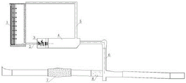
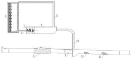
附图标记:1-发电分层取水进水口、2-有压隧洞、3-生态流量闸阀控制室、4-消力池、5-通气洞、6-竖井旋流消能工、7-低高程导流洞堵头段、8-封堵混凝土、9-斜井台阶消能工、10-竖井、11-水平消力墩消能工。Reference signs: 1-layered water intake for power generation, 2-pressurized tunnel, 3-ecological flow gate valve control room, 4-stilling pool, 5-ventilation tunnel, 6-shaft swirl energy dissipator, 7-low Plugging section of elevation diversion tunnel, 8-blocking concrete, 9-energy dissipator of inclined shaft steps, 10-shaft, 11-energy dissipator of horizontal stilling pier.
具体实施方式detailed description
下面结合附图和实施例对本发明作进一步的说明,但并不作为对本发明限制的依据。The present invention will be further described below in conjunction with the accompanying drawings and embodiments, but not as a basis for limiting the present invention.
本发明的实施例1:一种高水头生态流量泄水洞的布置结构,如图1和2所示,包括有发电分层取水进水口1,发电分层取水进水口1的侧边墩上预留开孔,该预留开孔通过有压隧洞2连接至生态流量闸阀控制室3,生态流量闸阀控制室3的出水流入消力池4,消力池4的出水口经竖井旋流消能工6与低高程导流洞堵头段7之后的隧洞连通。Embodiment 1 of the present invention: a layout structure of a high-head ecological flow discharge tunnel, as shown in Figures 1 and 2, includes a power generation layered water intake 1, and a side pier of the power generation layered water intake 1 The reserved opening is connected to the ecological flow gate valve control room 3 through the
本发明的实施例2:一种高水头生态流量泄水洞的布置结构,如图1和3所示,包括有发电分层取水进水口1,发电分层取水进水口1的侧边墩上预留开孔,该预留开孔通过有压隧洞2连接至生态流量闸阀控制室3,生态流量闸阀控制室3的出水流入消力池4,消力池4的出水口经斜井台阶消能工9与低高程导流洞堵头段7之后的隧洞连通。
本发明的实施例3:一种高水头生态流量泄水洞的布置结构,如图1和4所示,包括有发电分层取水进水口1,发电分层取水进水口1的侧边墩上预留开孔,该预留开孔通过有压隧洞2连接至生态流量闸阀控制室3,生态流量闸阀控制室3的出水流入消力池4,消力池4的出水口经第二次消能结构与低高程导流洞堵头段7之后的隧洞连通。第二次消能结构为竖井10和水平消力墩消能工11联合结构,消力池4的出水口经竖井10与低高程导流洞堵头段7之后的隧洞连通,低高程导流洞堵头段7之后的隧洞中间隔设置有水平消力墩消能工11。Embodiment 3 of the present invention: a layout structure of a high-head ecological flow discharge tunnel, as shown in Figures 1 and 4, includes a power generation stratified water intake 1, and a side pier of the power generation stratified water intake 1 The reserved opening is connected to the ecological flow gate valve control room 3 through the
实施例1、2和3的结构中,在低高程导流洞堵头段7后和竖井旋流消能工6、或斜井台阶消能工9、亦或竖井10之间增加封堵混凝土8。消力池4顶端经通气洞5与外部环境导通,以满足消力池4顶部的补排气功能,防止气爆现象对结构产生破坏。In the structures of Examples 1, 2 and 3, plugging concrete is added between the low-elevation diversion
工作原理:working principle:
本发明结构使用过程中,水流经发电分层取水进水口1的侧边墩上的预留开孔流入至有压隧洞2中,再通过有压隧洞2流入至生态流量闸阀控制室3,通过生态流量闸阀控制室3控制流量大小,闸阀控制室3出来的水流经过消力池4进行第一次消能,生态流量闸阀控制室3顶部设置通气洞5至发电分层取水进水口1顶部平台以满足消力池4顶部的补排气功能,防止气爆现象对结构产生破坏,消力池4中的水流可分别采用竖井旋流消能工6、或斜井台阶消能工9、亦或竖井10和水平消力墩消能工11联合的三种实施方案之一进行第二次消能,水流降落至低高程导流洞堵头段7之后的隧洞内,再排向下游河道。发电分层取水进水口1可根据上游不同水位及生态用水水质的要求控制取水区域,闸阀控制室3可根据上游不同水位调节闸阀开度控制生态流量的水量大小。为满足水力学条件,在低高程导流洞堵头段7后和竖井旋流消能工6、或斜井台阶消能工9、亦或竖井10之间增加封堵混凝土8。During the use of the structure of the present invention, the water flows into the
Claims (6)
Priority Applications (1)
| Application Number | Priority Date | Filing Date | Title |
|---|---|---|---|
| CN202211337049.7A CN115613529A (en) | 2022-10-28 | 2022-10-28 | Layout structure of a high head ecological flow discharge tunnel |
Applications Claiming Priority (1)
| Application Number | Priority Date | Filing Date | Title |
|---|---|---|---|
| CN202211337049.7A CN115613529A (en) | 2022-10-28 | 2022-10-28 | Layout structure of a high head ecological flow discharge tunnel |
Publications (1)
| Publication Number | Publication Date |
|---|---|
| CN115613529A true CN115613529A (en) | 2023-01-17 |
Family
ID=84876765
Family Applications (1)
| Application Number | Title | Priority Date | Filing Date |
|---|---|---|---|
| CN202211337049.7A Pending CN115613529A (en) | 2022-10-28 | 2022-10-28 | Layout structure of a high head ecological flow discharge tunnel |
Country Status (1)
| Country | Link |
|---|---|
| CN (1) | CN115613529A (en) |
Cited By (1)
| Publication number | Priority date | Publication date | Assignee | Title |
|---|---|---|---|---|
| CN117646404A (en) * | 2024-01-29 | 2024-03-05 | 陕西省水利电力勘测设计研究院 | System and method for discharging ecological flow in whole process of hydraulic junction engineering |
Citations (7)
| Publication number | Priority date | Publication date | Assignee | Title |
|---|---|---|---|---|
| JP2007177395A (en) * | 2005-12-26 | 2007-07-12 | Chugoku Electric Power Co Inc:The | Energy dissipation works of spillway water flow and energy dissipation method |
| CN101638888A (en) * | 2009-07-24 | 2010-02-03 | 中国水利水电科学研究院 | Flood discharging method for anticorrosion and energy dissipation of rotational flow ring dam and device thereof |
| CN103898882A (en) * | 2014-04-21 | 2014-07-02 | 四川大学 | Classified pool-inlet high-dam flood discharge energy dissipater for bottom flow and energy dissipating method |
| CN104264639A (en) * | 2014-09-11 | 2015-01-07 | 四川大学 | Underflow type stair stilling pool energy consumption system |
| CN105804027A (en) * | 2016-05-11 | 2016-07-27 | 中国电建集团成都勘测设计研究院有限公司 | Temporary discharge structure reducing ecological flow of low-temperature water for high dam |
| CN208219579U (en) * | 2018-05-02 | 2018-12-11 | 中国电建集团西北勘测设计研究院有限公司 | The structure that a kind of diversion tunnel and ecological drainage tunnel combine |
| CN112343016A (en) * | 2020-11-10 | 2021-02-09 | 中铁第四勘察设计院集团有限公司 | Combined energy dissipation structure of flood discharge tunnel |
-
2022
- 2022-10-28 CN CN202211337049.7A patent/CN115613529A/en active Pending
Patent Citations (7)
| Publication number | Priority date | Publication date | Assignee | Title |
|---|---|---|---|---|
| JP2007177395A (en) * | 2005-12-26 | 2007-07-12 | Chugoku Electric Power Co Inc:The | Energy dissipation works of spillway water flow and energy dissipation method |
| CN101638888A (en) * | 2009-07-24 | 2010-02-03 | 中国水利水电科学研究院 | Flood discharging method for anticorrosion and energy dissipation of rotational flow ring dam and device thereof |
| CN103898882A (en) * | 2014-04-21 | 2014-07-02 | 四川大学 | Classified pool-inlet high-dam flood discharge energy dissipater for bottom flow and energy dissipating method |
| CN104264639A (en) * | 2014-09-11 | 2015-01-07 | 四川大学 | Underflow type stair stilling pool energy consumption system |
| CN105804027A (en) * | 2016-05-11 | 2016-07-27 | 中国电建集团成都勘测设计研究院有限公司 | Temporary discharge structure reducing ecological flow of low-temperature water for high dam |
| CN208219579U (en) * | 2018-05-02 | 2018-12-11 | 中国电建集团西北勘测设计研究院有限公司 | The structure that a kind of diversion tunnel and ecological drainage tunnel combine |
| CN112343016A (en) * | 2020-11-10 | 2021-02-09 | 中铁第四勘察设计院集团有限公司 | Combined energy dissipation structure of flood discharge tunnel |
Non-Patent Citations (1)
| Title |
|---|
| 徐国宾: "《河工学》", 31 October 2011, 中国科学技术出版社, pages: 991 * |
Cited By (2)
| Publication number | Priority date | Publication date | Assignee | Title |
|---|---|---|---|---|
| CN117646404A (en) * | 2024-01-29 | 2024-03-05 | 陕西省水利电力勘测设计研究院 | System and method for discharging ecological flow in whole process of hydraulic junction engineering |
| CN117646404B (en) * | 2024-01-29 | 2024-05-03 | 陕西省水利电力勘测设计研究院 | A whole-process ecological flow release system and method for a water conservancy project |
Similar Documents
| Publication | Publication Date | Title |
|---|---|---|
| WO2020125601A1 (en) | Emptying system for high dam | |
| CN108797526A (en) | Multifunctional ecological for extra-high rock-fill dams is for water hole arrangement | |
| CN110528475A (en) | A water intake system for water conservancy projects | |
| CN115613529A (en) | Layout structure of a high head ecological flow discharge tunnel | |
| CN207919510U (en) | Diversion tunnel blocks arrangement using lock under permanent plug first section joint gate | |
| CN107975015A (en) | It is provided with the checkdam of surface spillways | |
| CN205501944U (en) | To downstream water supply structure suitable for high arch dam | |
| CN201933472U (en) | Dam structure utilizing flaring piers and dam face small flip buckets to jointly discharge flood and dissipate energy | |
| CN110258474A (en) | It can be used for the ecological diversion tunnel structure that extra-high rock-fill dams major flood season is passed the flood period | |
| CN104099909B (en) | Based on the flood discharge generating sync energy dissipater of flood-discharge tunnel | |
| CN212896234U (en) | Connection structure of bank spillway slow-leveling section and steep groove section | |
| CN108316259A (en) | Diversion tunnel sets up lock under interim plug joint gate and blocks arrangement and method | |
| CN102561290A (en) | Ship lock integrated with navigation, power generation and flood discharge | |
| CN202899094U (en) | Large-scale gate pier for water gate projects | |
| CN101294378A (en) | A flood discharge steep trough equipped with water flow counteracting energy dissipating sill | |
| CN207159958U (en) | Non-close is without pump drainage cushion pool structure | |
| CN206752427U (en) | A kind of power station ground power house tailrace outlet structure and its power station | |
| CN206971181U (en) | A kind of multichannel bank stiling basin of dispersible energy dissipating | |
| CN204385701U (en) | Be applicable to surface current underflow combined energy dissipater and the water-control project of wide shallow river course porous gate dam | |
| CN205604193U (en) | High dam reservoir emptying device | |
| CN206143743U (en) | Husky corridor system is arranged to power station water inlet | |
| CN201212143Y (en) | A flood discharge steep trough equipped with water flow counteracting energy dissipating sill | |
| CN211849316U (en) | A post-dam power station ecological flow discharge facility that takes into account both benefits and monitoring needs | |
| CN107893406A (en) | Lock blocks program under a kind of diversion tunnel group | |
| CN209873741U (en) | A multifunctional reservoir |
Legal Events
| Date | Code | Title | Description |
|---|---|---|---|
| PB01 | Publication | ||
| PB01 | Publication | ||
| SE01 | Entry into force of request for substantive examination | ||
| SE01 | Entry into force of request for substantive examination | ||
| RJ01 | Rejection of invention patent application after publication | ||
| RJ01 | Rejection of invention patent application after publication |
Application publication date: 20230117 |