CN115598530B - Method and device for evaluating no-load characteristics of generator, electronic equipment and storage medium - Google Patents
Method and device for evaluating no-load characteristics of generator, electronic equipment and storage medium Download PDFInfo
- Publication number
- CN115598530B CN115598530B CN202211503700.3A CN202211503700A CN115598530B CN 115598530 B CN115598530 B CN 115598530B CN 202211503700 A CN202211503700 A CN 202211503700A CN 115598530 B CN115598530 B CN 115598530B
- Authority
- CN
- China
- Prior art keywords
- matrix
- stator voltage
- generator
- magnitude
- coefficient
- Prior art date
- Legal status (The legal status is an assumption and is not a legal conclusion. Google has not performed a legal analysis and makes no representation as to the accuracy of the status listed.)
- Active
Links
- 238000000034 method Methods 0.000 title claims abstract description 44
- 239000011159 matrix material Substances 0.000 claims abstract description 143
- 238000012360 testing method Methods 0.000 claims abstract description 93
- 238000012797 qualification Methods 0.000 claims abstract description 47
- 238000011156 evaluation Methods 0.000 claims abstract description 33
- 230000005284 excitation Effects 0.000 claims description 18
- 238000004590 computer program Methods 0.000 claims description 16
- 238000004364 calculation method Methods 0.000 claims description 9
- 230000005856 abnormality Effects 0.000 claims description 6
- 238000013441 quality evaluation Methods 0.000 claims description 3
- 238000004891 communication Methods 0.000 description 8
- 238000012545 processing Methods 0.000 description 6
- 238000010586 diagram Methods 0.000 description 5
- 230000003287 optical effect Effects 0.000 description 3
- 230000008569 process Effects 0.000 description 3
- 230000006870 function Effects 0.000 description 2
- 230000003993 interaction Effects 0.000 description 2
- 238000012986 modification Methods 0.000 description 2
- 230000004048 modification Effects 0.000 description 2
- 238000004458 analytical method Methods 0.000 description 1
- 238000003491 array Methods 0.000 description 1
- 238000013473 artificial intelligence Methods 0.000 description 1
- 230000009286 beneficial effect Effects 0.000 description 1
- 230000001413 cellular effect Effects 0.000 description 1
- 230000008859 change Effects 0.000 description 1
- 230000007547 defect Effects 0.000 description 1
- 238000013461 design Methods 0.000 description 1
- 238000002474 experimental method Methods 0.000 description 1
- 239000011521 glass Substances 0.000 description 1
- 239000004973 liquid crystal related substance Substances 0.000 description 1
- 238000010801 machine learning Methods 0.000 description 1
- 239000013307 optical fiber Substances 0.000 description 1
- 230000002441 reversible effect Effects 0.000 description 1
- 239000004065 semiconductor Substances 0.000 description 1
- 230000001953 sensory effect Effects 0.000 description 1
- 238000006467 substitution reaction Methods 0.000 description 1
- 230000000007 visual effect Effects 0.000 description 1
- 238000004804 winding Methods 0.000 description 1
Images


Classifications
-
- G—PHYSICS
- G01—MEASURING; TESTING
- G01R—MEASURING ELECTRIC VARIABLES; MEASURING MAGNETIC VARIABLES
- G01R31/00—Arrangements for testing electric properties; Arrangements for locating electric faults; Arrangements for electrical testing characterised by what is being tested not provided for elsewhere
- G01R31/34—Testing dynamo-electric machines
Abstract
The embodiment of the invention discloses an evaluation method and device of no-load characteristics of a generator, electronic equipment and a storage medium. The method comprises the following steps: acquiring stator voltage and rotor exciting current generated by a target generator in at least one no-load characteristic test; determining a first magnitude matrix and a second magnitude matrix according to each stator voltage and each rotor exciting current; determining a stator voltage quality qualification coefficient of a target generator; and evaluating the no-load characteristic quality of the target generator according to the first magnitude matrix, the second magnitude matrix and the stator voltage quality qualification coefficient. According to the scheme provided by the embodiment of the invention, the no-load characteristic of the generator can be rapidly and accurately evaluated.
Description
Technical Field
The embodiment of the invention relates to the technical field of generators, in particular to a method and a device for evaluating no-load characteristics of a generator, electronic equipment and a storage medium.
Background
The no-load characteristic of the generator is the relationship between the stator voltage and the rotor exciting current when the generator is at rated rotation speed and the stator outlet is open circuit and the load current is zero. The relation curve of the stator voltage and the rotor exciting current is an important factor for evaluating the reliability of the unit, and can be used for judging whether the rotor winding has turn-to-turn short circuit fault or not and also can be used for detecting the saturation degree of the generator magnetic circuit. In a unit starting test, a generator no-load characteristic test is an important item, and whether the unit can change from a no-load working condition test to a load working condition test is determined, so that the stability and reliability of the grid-connected operation of the generator are affected.
However, the current method for evaluating the no-load characteristic of the generator is a macroscopic image comparison method, which is to compare the measured stator voltage and rotor exciting current relationship curve with the original data curve provided by the manufacturer. The evaluation method is rough, has larger error, cannot compare the nuances of the relation curves, and cannot evaluate the no-load characteristics of the generator rapidly and accurately.
Disclosure of Invention
The embodiment of the invention provides a method, a device, electronic equipment and a storage medium for evaluating the no-load characteristic of a generator, so as to evaluate the no-load characteristic of the generator rapidly and accurately.
According to an aspect of the embodiment of the present invention, there is provided a method for evaluating no-load characteristics of a generator, including:
acquiring stator voltage and rotor exciting current generated by a target generator in at least one no-load characteristic test;
determining a first magnitude matrix and a second magnitude matrix from each of the stator voltages and each of the rotor excitation currents;
determining a stator voltage quality qualification coefficient of the target generator;
and evaluating the no-load characteristic quality of the target generator according to the first magnitude matrix, the second magnitude matrix and the stator voltage quality qualification coefficient.
According to another aspect of the embodiment of the present invention, there is provided an apparatus for evaluating no-load characteristics of a generator, including:
the acquisition module is used for acquiring stator voltage and rotor exciting current generated by the target generator in at least one no-load characteristic test;
a first determination module for determining a first magnitude matrix and a second magnitude matrix from each of the stator voltages and each of the rotor excitation currents;
the second determining module is used for determining the quality qualification coefficient of the stator voltage of the target generator;
and the evaluation module is used for evaluating the no-load characteristic quality of the target generator according to the first magnitude matrix, the second magnitude matrix and the stator voltage quality qualification coefficient.
According to another aspect of an embodiment of the present invention, there is provided an electronic apparatus including:
at least one processor; and
a memory communicatively coupled to the at least one processor; wherein,
the memory stores a computer program executable by the at least one processor to enable the at least one processor to perform the method for evaluating the no-load characteristics of the generator according to any of the embodiments of the present invention.
According to another aspect of the embodiments of the present invention, there is provided a computer readable storage medium storing computer instructions for causing a processor to implement the method for evaluating no-load characteristics of a generator according to any of the embodiments of the present invention when executed.
According to the technical scheme, the stator voltage and the rotor exciting current generated by the target generator in at least one no-load characteristic test are obtained; determining a first magnitude matrix and a second magnitude matrix from each of the stator voltages and each of the rotor excitation currents; determining a stator voltage quality qualification coefficient of the target generator; the no-load characteristic quality of the target generator is evaluated according to the first magnitude matrix, the second magnitude matrix and the stator voltage quality qualification coefficient, so that the no-load characteristic of the generator can be evaluated rapidly and accurately.
It should be understood that the description in this section is not intended to identify key or critical features of the embodiments of the invention, nor is it intended to be used to limit the scope of the embodiments of the invention. Other features of embodiments of the present invention will become apparent from the description that follows.
Drawings
In order to more clearly illustrate the technical solutions of the embodiments of the present invention, the drawings that are needed in the description of the embodiments will be briefly described below, and it is obvious that the drawings in the following description are only some embodiments of the present invention, and other drawings may be obtained according to these drawings without inventive effort for a person skilled in the art.
FIG. 1 is a flow chart of a method for evaluating no-load characteristics of a generator according to a first embodiment of the present invention;
fig. 2 is a schematic structural diagram of an apparatus for evaluating no-load characteristics of a generator according to a third embodiment of the present invention;
fig. 3 is a schematic structural diagram of an electronic device implementing a method for evaluating no-load characteristics of a generator according to an embodiment of the present invention.
Detailed Description
In order to make the embodiments of the present invention better understood by those skilled in the art, the technical solutions of the embodiments of the present invention will be clearly and completely described below with reference to the accompanying drawings in the embodiments of the present invention, and it is apparent that the described embodiments are only some embodiments of the present invention, not all embodiments. All other embodiments, which can be made by one of ordinary skill in the art without undue burden from the present disclosure, are intended to be within the scope of the embodiments of the present invention.
It should be noted that the terms "first," "second," and the like in the description and the claims of the embodiments of the present invention and the above-described drawings are used for distinguishing between similar objects and not necessarily for describing a particular sequential or chronological order. It is to be understood that the data so used may be interchanged where appropriate such that embodiments of the invention described herein may be implemented in sequences other than those illustrated or otherwise described herein. Furthermore, the terms "comprises," "comprising," and "having," and any variations thereof, are intended to cover a non-exclusive inclusion, such that a process, method, system, article, or apparatus that comprises a list of steps or elements is not necessarily limited to those steps or elements expressly listed but may include other steps or elements not expressly listed or inherent to such process, method, article, or apparatus.
Example 1
Fig. 1 is a flowchart of a method for evaluating no-load characteristics of a generator according to an embodiment of the present invention, where the method may be performed by an apparatus for evaluating no-load characteristics of a generator, the apparatus may be implemented in hardware and/or software, and the apparatus may be configured in an electronic device such as a computer, a server, or a tablet computer. Specifically, referring to fig. 1, the method specifically includes the following steps:
The target generator can be any generator in a pumped storage generator set or a diesel generator set and other generator sets; for example, if the pumped-storage generator set includes three generators in total, then the target generator may be any one of the generators.
In the embodiment, the number of the generators is taken asnTaking the number of no-load characteristic tests of each generator asmLet the rated voltage of the generator stator beU N . A pumped storage power station is generally provided with 3-4 generators, the 1 st no-load characteristic test is generally a model test, and the 2 nd no-load characteristic test is generally a whole set of start-up phase test. In the no-load characteristic test evaluation, the 2 nd test is used as a base reference.
In an alternative implementation of this embodiment, the stator voltage and the rotor excitation current generated by the target generator in the 2 nd-6 th no-load characteristic test may be sequentially acquired.
In an alternative implementation manner of the present embodiment, obtaining the stator voltage and the rotor exciting current generated by the target generator in at least one no-load characteristic test may include: continuously performing a first no-load characteristic test at least twice through the target generator; wherein, the stator voltage of each no-load characteristic test is increased by a preset number multiple; each stator voltage generated by each first no-load characteristic test is obtained, and a first stator voltage matrix is generated; and obtaining exciting currents of each rotor generated by each first no-load characteristic test, and generating a first rotor exciting current matrix.
Exemplary, if the generator stator is rated at voltage U N In each no-load characteristic experiment, the stator voltage can be increased by 0.2 times of U N . It can be understood that the stator voltage and the rotor exciting current generated by the target generator in at least one no-load characteristic test are obtained, namely n=1; that is, when n=1 is obtained, the data of the stator voltage and the rotor exciting current of the target generator in m tests are calculated, and the voltage and current data multidimensional matrix s1= { U1m, I1m }. M tests on 1 st GeneratorEvery 0.2 times U of the stator voltage N Corresponding stator voltage and rotor exciting current are recorded, and the recording frequency is set as t. Counting the recorded stator voltage matrix, i.e. the first stator voltage matrix is U 1m ={U 1m1 ,U 1m2 ,U 1m3 ,…,U 1mt The rotor exciting current matrix, i.e. the first rotor exciting current matrix is I 1m ={I 1m1 ,I 1m2 ,I 1m3 ,…,I 1mt }. In the present embodiment, the maximum stator voltage is not more than 1.2 times U N Therefore, the recording frequency t is generally 6.
Further, obtaining the stator voltage and the rotor excitation current generated by the target generator in at least one no-load characteristic test may further include: continuously performing at least two second no-load characteristic tests through the target generator and at least one reference generator; wherein each reference generator and the target generator are deployed in the same pumped storage power station or substation; each stator voltage generated by each second no-load characteristic test is obtained, and a second stator voltage matrix is generated; and obtaining each rotor exciting current generated by each second no-load characteristic test, and generating a second rotor exciting current matrix.
The reference generator is other generators in the pumped storage generator set, and if the pumped storage generator set includes 4 generators, the reference generator is other 3 generators except the target generator.
Optionally, in this embodiment, the second no-load characteristic test is performed at least twice in succession by the target generator and at least one reference generator; each stator voltage generated by each second no-load characteristic test is obtained, and a second stator voltage matrix is generated; obtaining each rotor exciting current generated by each second no-load characteristic test, and generating a second rotor exciting current matrix, namely obtainingmWhen the number of the codes is =2,ndata of stator voltage and rotor exciting current of generator, statistical voltage and current data multidimensional matrix S 2 ={U n2 ,I n2 }. At test 2 of A-stage generator, stator electricityEvery 0.2 times of U N Corresponding stator voltage and rotor exciting current are recorded, and the recording frequency is set asl. Counting the recorded stator voltage matrix, namely the second electronic voltage matrix, as U n2 ={U n21 ,U n22 ,U n23 ,…,U n l2 A rotor exciting current matrix, namely a second rotor exciting current matrix is I n1 ={I n21 ,I n22 ,I n23 ,…,I n l2 }. In the present embodiment, the maximum stator voltage is not more than 1.2 times U N So the recording frequencylGenerally 6.
It should be noted that, the first magnitude matrix related in this embodiment refers to a performance state evaluation magnitude matrix obtained by calculation according to stator voltage and rotor exciting current data of different stages of no-load characteristic tests of the same generator; the second magnitude matrix is a performance state evaluation magnitude matrix obtained by calculation according to stator voltage and rotor exciting current data of the same-stage no-load characteristic test of different generators.
In an alternative implementation manner of the present embodiment, after the stator voltage and the rotor exciting current generated by the target generator in at least one no-load characteristic test are acquired, that is, after the first stator voltage matrix, the first rotor exciting current matrix, the second stator voltage matrix and the second rotor exciting current matrix are acquired, the first magnitude matrix and the second magnitude matrix may be further determined according to the acquired stator voltages and rotor exciting currents.
Optionally, in this embodiment, determining the first magnitude matrix and the second magnitude matrix according to each of the stator voltages and each of the rotor excitation currents may include: determining each first correlation coefficient according to the first stator voltage matrix and the first rotor exciting current matrix; combining the first correlation coefficients to obtain the first magnitude matrix; determining each second correlation coefficient according to the second stator voltage matrix and the second rotor excitation current matrix; and combining the second phase relation numbers to obtain the second magnitude matrix.
In an alternative implementation of this embodiment, the first correlation coefficient may be calculated by the following formula:

wherein,  1 st generatormSecondary testtAn average of the secondary voltage recorded values;
 1 st generatormSecondary testtAverage of secondary current recorded values.
In this embodiment, the target generator is set as the 1 st generator, and the above equation is to calculate the correlation coefficient of the m-th test data matrix of the 1 st generator. Alternatively, in this embodiment, after all the first correlation coefficients are calculated by the above equation, the first correlation coefficients may be combined to obtain a self-estimated-amount correlation coefficient matrix, i.e., a first magnitude matrixE 1 ={r 11 ,r 12 ,r 13 ……r m1 }。
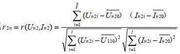
In an alternative implementation of this embodiment, the second phase relationship may be calculated by the following formula:

wherein,  is the firstnTest of bench generator 2 nd timelSecondary electric powerAn average value of the recorded values;
 is the firstnTest of bench generator 2 nd timelAverage of secondary current recorded values.
It should be noted that the above equation is to calculate the correlation coefficient of the test data matrix of the nth generator at the 2 nd time. Alternatively, in this embodiment, after all the second phase relation numbers are calculated by the above equation, the second phase relation numbers may be combined to obtain a second magnitude matrix, which is a correlation coefficient matrix of the mutual evaluation amount E 2 ={r 21 ,r 22 ,r 23 ……r n2 }。
And 130, determining the quality qualification coefficient of the stator voltage of the target generator.
In an alternative implementation of this embodiment, after the first magnitude matrix and the second magnitude matrix are calculated, the stator voltage quality eligibility coefficient of the target generator may be further determined.
Optionally, in this embodiment, determining the quality qualification coefficient of the stator voltage of the target generator may include: and acquiring a stator voltage waveform of the target generator in a target no-load characteristic test, and determining a stator voltage quality qualification coefficient of the target generator according to the stator voltage waveform.
In an alternative implementation of this embodiment, determining the stator voltage quality eligibility coefficient of the target generator according to the stator voltage waveform may include: determining a telephone harmonic pass coefficient and a voltage waveform distortion pass coefficient of the stator voltage waveform; determining a stator voltage quality qualification coefficient of the target generator according to the product result of the telephone harmonic qualification coefficient and the voltage waveform distortion qualification coefficient;
wherein the determining the phone harmonic pass coefficient and the voltage waveform distortion pass coefficient of the stator voltage waveform comprises: determining the phone harmonic pass coefficient based on the following formula:

Wherein, THFfor a telephone harmonic factor, the telephone harmonic factor is determined based on the following formula:

wherein, Uis the effective value of the line voltage;E i is thatiAn effective value of the subharmonic voltage;λ i corresponding toiWeighting coefficients of subharmonic frequencies; determining the voltage waveform distortion qualification coefficient based on the following formula:

wherein, THDfor a voltage waveform abnormality rate, the voltage waveform abnormality rate is determined based on the following formula:

wherein, nis the harmonic frequency;u n is the firstnThe ratio of the subharmonic voltage amplitude to the fundamental voltage amplitude.
Further, the stator voltage quality qualification coefficient of the target generatorQ=Q THF *Q THD 。
And 140, evaluating the no-load characteristic quality of the target generator according to the first magnitude matrix, the second magnitude matrix and the stator voltage quality qualification coefficient.
In an optional implementation manner of this embodiment, after the first magnitude matrix, the second magnitude matrix and the stator voltage quality qualification coefficient are calculated through the foregoing steps, the no-load characteristic quality of the target generator may be further evaluated according to the calculated first magnitude matrix, second magnitude matrix and stator voltage quality qualification coefficient.
Optionally, in this embodiment, evaluating the quality of the no-load characteristic of the target generator according to the first magnitude matrix, the second magnitude matrix, and the stator voltage quality qualification coefficient includes: determining a first magnitude from the first magnitude matrix and a second magnitude from the second magnitude matrix; determining an idle characteristic quality comprehensive evaluation coefficient according to the first magnitude, the second magnitude and the stator voltage quality qualification coefficient; and evaluating the idle characteristic quality of the target generator according to the comprehensive idle characteristic quality evaluation coefficient.
In this embodiment, determining the first magnitude from the first magnitude matrix may be based on the first magnitude matrix E 1 ={r 11 ,r 12 ,r 13 ……r 1m Calculating a first magnitude E 1 : alternatively, in the present embodiment, the first magnitude may be determined based on the following formula:

in this embodiment, determining the second magnitude from the second magnitude matrix may be based on a second magnitude matrix E 2 ={r 21 ,r 22 ,r 23 ……r 2n Calculating a second magnitude E 2 : alternatively, in the present embodiment, the second magnitude may be determined based on the following formula:

further, it is possible to determine the first magnitude E of the generator 1 Second magnitude E 2 Quality qualification coefficient of stator voltageQCalculating the comprehensive evaluation value of the no-load characteristic quality of the generatorη:η=Q*(E 1 +E 2 ) The method comprises the steps of carrying out a first treatment on the surface of the Further, it is possible according to the followingAnd the idle characteristic quality comprehensive evaluation coefficient evaluates the idle characteristic quality of the target generator.
Exemplary, in the present embodiment, if 1.6 <ηLess than or equal to 2, strong correlation and qualified no-load characteristic test; if 1.4 <ηLess than or equal to 1.6, medium correlation, possible slight problems of turn-to-turn short circuit of the generator rotor or supersaturation of the magnetic circuit, and carrying out the test again after finding out the reason; if it isηLess than or equal to 1.4, weak correlation and unqualified no-load characteristic test.
According to the technical scheme, stator voltage and rotor exciting current generated by a target generator in at least one no-load characteristic test are obtained; determining a first magnitude matrix and a second magnitude matrix from each of the stator voltages and each of the rotor excitation currents; determining a stator voltage quality qualification coefficient of the target generator; the no-load characteristic quality of the target generator is evaluated according to the first magnitude matrix, the second magnitude matrix and the stator voltage quality qualification coefficient, so that the no-load characteristic of the generator can be evaluated rapidly and accurately.
In order to better understand the method for evaluating the no-load characteristics of the generator according to the embodiment of the present invention, a specific example will be described below:
in this example, taking a pumped-storage power station as an example, the power station has 4 300MW reversible hydroelectric generating sets, and the power station is based on 1 set of no-load characteristic data in the 4 set model test stage, 2 sets of no-load characteristic data in the whole set start test stage (i.e.n=4,m=3), the no-load characteristic quality of the 1 st generator was evaluated.
And step 1, collecting stator voltage and rotor exciting current data of a generator no-load test.
(1) First, theNo. 1 set of no-load characteristic data for the 1 st stage of the generator model test (i.en=1,m=1):U 11 = {3.624,7.236, 10.815, 14.517, 18.213, 21.678} (unit: kV), I 11 = {0.306,0.612,0.918,1.224,1.530,1.836} (unit: kA);
(2) Group 1 no-load characteristic data of the entire group 1 generator start-up test phase (i.e n=1,m=2):U 12 = {3.604,7.204, 10.801, 14.412, 18.004, 21.611} (unit: kV), I 12 = {0.334,0.593,0.934,1.271,1.404,1.765} (unit: kA);
(3) Group 2 no-load characteristic data of the entire group start-up test phase of the 1 st generator (i.en=1,m=3):U 13 = {3.602,7.211, 10.811, 14.401, 18.016, 21.642} (unit: kV), I 13 = {0.343,0.594,0.955,1.298,1.612,1.985} (unit: kA).
(1) Group 1 no-load characteristic data of the entire group 1 generator start-up test phase (i.en=1,m=2):U 12 = {3.604,7.204, 10.801, 14.412, 18.004, 21.611} (unit: kV), I 12 = {0.334,0.593,0.934,1.271,1.404,1.765} (unit: kA);
(2) Group 1 no-load characteristic data of the entire group start-up test phase of the 2 nd generator (i.en=2,m=2):U 22 = {3.612,7.210, 10.803, 14.421, 18.172, 21.644} (unit: kV), I 22 = {0.274,0.623,0.876,1.112,1.582,1.896} (unit: kA);
(3) Group 1 no-load characteristic data of the entire group start-up test phase of the 3 rd generator (i.en=3,m=2):U 32 = {3.607,7.708, 10.912, 14.512, 17.965, 22.612} (unit: kV), I 32 ={0.353,0.601,0.945,1.392,1.601,2.011} (units: kA);
(4) Group 1 no-load characteristic data of the entire group of 4 generators during the start-up test phase (i.en=4,m=2):U 42 ={3.609,7.213,10.822,14.522,18.567,21.878},I 42 = {0.351,0.582,0.915,1.323,1.756,2.134} (unit: kA).
Step 2, calculating a self-evaluation magnitude matrix of the no-load performance of the generatorE 1 。
According to the 1 st set of no-load characteristic data of the 1 st generator model test stage collected in the step 11 and the 2 sets of no-load characteristic data of the whole set of starting test stage, combining the formula Calculation ofE 1 :
E 1 ={r 11 ,r 12 ,r 13 }={0.99996,0.99540,0.99891}
Calculating the self-evaluation value of the no-load performance of a generatorE 1 :

Step 3, calculating a generator no-load performance mutual evaluation magnitude matrixE 2 。
According to 1 group of no-load characteristic data collected in step 12 in the whole group of 4 generators starting test stage, combining the formula
E 2 ={r 21 ,r 22 ,r 23 ,r 24 }={0.99540,0.99552,0.99534,0.99640}
Calculating the self-evaluation value of the no-load performance of a generatorE 2 :

Step 4, calculating the quality qualification coefficient of the stator voltage of the generatorQ。
Extracting stator voltage waveform data of a 1 st group no-load test of the whole group of the 1 st generator in a starting test stage, and sequentially calculating the qualification coefficients of the harmonic factors of the telephone Q THF And a voltage waveform distortion factorQ THD :
(1) According to the formula Obtaining Telephone Harmonic Factor (THF): THF (%) =0.214% < 1.5%.
According to the formula Obtaining the qualified coefficient of the harmonic factor of the telephoneQ THF =1。
(2) According to the formula Obtaining a voltage waveform distortion rate (THD): THD (%) =1.748% < 5%.
According to the formula Obtaining the distortion coefficient of the voltage waveformQ THD =1。
Therefore, it isQ=Q THF *Q THD =1*1=1。
Step 5, calculating the comprehensive evaluation value of the no-load characteristic quality of the generatorη。
Generator no-load performance self-evaluation magnitude matrix calculated according to step 2-4E 1 Mutual evaluation magnitude matrix for no-load performance of generatorE 2 Quality qualification coefficient of generator stator voltageQCombining the formula eta=Q*(E 1 +E 2 ) Obtaining the comprehensive evaluation value of the no-load characteristic quality of the generatorη:
η=Q*(E 1 +E 2 )=1*(0.99809+0.99567)=1.99376
Because ofηIn [1.6, 2]And (3) can judge that the no-load characteristic of the generator is qualified.
According to the embodiment of the invention, the self-evaluation magnitude of the no-load performance of the generator can be sequentially carried out according to the obtained data matrix of the stator voltage and the rotor exciting current of the no-load test of the generatorE 1 Mutual evaluation valueE 2 Quality qualification coefficient of stator voltageQTo obtain comprehensive evaluation valueηAnd evaluating the no-load characteristic quality of the generator. Compared with the traditional image comparison method, the method and the device for evaluating the no-load characteristics of the power generator utilize a quantifiable numerical calculation analysis mode, improve the accuracy of no-load characteristic evaluation, and effectively test the running quality of the power generator.
Example two
Fig. 2 is a schematic structural diagram of an apparatus for evaluating no-load characteristics of a generator according to a third embodiment of the present invention. As shown in fig. 2, the apparatus includes: the acquisition module 210, the first determination module 220, the second determination module 230, and the evaluation module 240.
An acquisition module 210, configured to acquire a stator voltage and a rotor excitation current generated by the target generator in at least one no-load characteristic test;
a first determining module 220 for determining a first magnitude matrix and a second magnitude matrix from each of the stator voltages and each of the rotor excitation currents;
a second determination module 230 for determining a stator voltage quality acceptance coefficient of the target generator;
an evaluation module 240, configured to evaluate the no-load characteristic quality of the target generator according to the first magnitude matrix, the second magnitude matrix, and the stator voltage quality qualification coefficient.
According to the scheme of the embodiment, the stator voltage and the rotor exciting current generated by the target generator in at least one no-load characteristic test are obtained through the obtaining module; determining, by a first determination module, a first magnitude matrix and a second magnitude matrix from each of the stator voltages and each of the rotor excitation currents; determining a stator voltage quality qualification coefficient of the target generator through a second determination module; the no-load characteristic quality of the target generator is evaluated according to the first magnitude matrix, the second magnitude matrix and the stator voltage quality qualification coefficient by the evaluation module, so that the no-load characteristic of the generator can be evaluated rapidly and accurately.
In an alternative implementation manner of this embodiment, the obtaining module 210 is specifically configured to continuously perform the first no-load characteristic test at least twice through the target generator; wherein, the stator voltage of each no-load characteristic test is increased by a preset number multiple;
each stator voltage generated by each first no-load characteristic test is obtained, and a first stator voltage matrix is generated;
and obtaining exciting currents of each rotor generated by each first no-load characteristic test, and generating a first rotor exciting current matrix.
In an alternative implementation manner of this embodiment, the obtaining module 210 is further specifically configured to continuously perform the second no-load characteristic test at least twice through the target generator and the at least one reference generator; wherein each reference generator and the target generator are deployed in the same pumped storage power station or substation;
each stator voltage generated by each second no-load characteristic test is obtained, and a second stator voltage matrix is generated;
and obtaining each rotor exciting current generated by each second no-load characteristic test, and generating a second rotor exciting current matrix.
In an optional implementation manner of this embodiment, the first determining module 220 is specifically configured to determine each first correlation coefficient according to the first stator voltage matrix and the first rotor exciting current matrix;
Combining the first correlation coefficients to obtain the first magnitude matrix;
determining each second correlation coefficient according to the second stator voltage matrix and the second rotor excitation current matrix;
and combining the second phase relation numbers to obtain the second magnitude matrix.
In an alternative implementation manner of this embodiment, the second determining module 230 is specifically configured to obtain a stator voltage waveform of the target generator in the target no-load characteristic test, and determine a quality qualification coefficient of the stator voltage of the target generator according to the stator voltage waveform.
In an alternative implementation manner of this embodiment, the second determining module 230 is further specifically configured to determine a phone harmonic pass coefficient of the stator voltage waveform and a voltage waveform distortion pass coefficient;
determining a stator voltage quality qualification coefficient of the target generator according to the product result of the telephone harmonic qualification coefficient and the voltage waveform distortion qualification coefficient;
wherein the determining the phone harmonic pass coefficient and the voltage waveform distortion pass coefficient of the stator voltage waveform comprises:
determining the phone harmonic pass coefficient based on the following formula:

Wherein, THFfor a telephone harmonic factor, the telephone harmonic factor is determined based on the following formula:

wherein, Uis the effective value of the line voltage;E i is thatiAn effective value of the subharmonic voltage;λ i corresponding toiWeighting coefficients of subharmonic frequencies;
determining the voltage waveform distortion qualification coefficient based on the following formula:

wherein, THDfor a voltage waveform abnormality rate, the voltage waveform abnormality rate is determined based on the following formula:

wherein, nis the harmonic frequency;u n is the firstnThe ratio of the subharmonic voltage amplitude to the fundamental voltage amplitude.
In an alternative implementation of the present embodiment, the evaluation module 240 is specifically configured to determine a first magnitude according to the first magnitude matrix, and determine a second magnitude according to the second magnitude matrix;
determining an idle characteristic quality comprehensive evaluation coefficient according to the first magnitude, the second magnitude and the stator voltage quality qualification coefficient;
and evaluating the idle characteristic quality of the target generator according to the comprehensive idle characteristic quality evaluation coefficient.
The device for evaluating the no-load characteristic of the generator provided by the embodiment of the invention can execute the method for evaluating the no-load characteristic of the generator provided by any embodiment of the invention, and has the corresponding functional modules and beneficial effects of the executing method.
Example III
Fig. 3 shows a schematic diagram of an electronic device 10 that may be used to implement an embodiment of the invention. Electronic devices are intended to represent various forms of digital computers, such as laptops, desktops, workstations, personal digital assistants, servers, blade servers, mainframes, and other appropriate computers. Electronic equipment may also represent various forms of mobile devices, such as personal digital processing, cellular telephones, smartphones, wearable devices (e.g., helmets, glasses, watches, etc.), and other similar computing devices. The components shown herein, their connections and relationships, and their functions, are meant to be exemplary only, and are not meant to limit implementations of the embodiments of the invention described and/or claimed herein.
As shown in fig. 3, the electronic device 10 includes at least one processor 11, and a memory, such as a Read Only Memory (ROM) 12, a Random Access Memory (RAM) 13, etc., communicatively connected to the at least one processor 11, in which the memory stores a computer program executable by the at least one processor, and the processor 11 may perform various appropriate actions and processes according to the computer program stored in the Read Only Memory (ROM) 12 or the computer program loaded from the storage unit 18 into the Random Access Memory (RAM) 13. In the RAM 13, various programs and data required for the operation of the electronic device 10 may also be stored. The processor 11, the ROM 12 and the RAM 13 are connected to each other via a bus 14. An input/output (I/O) interface 15 is also connected to bus 14.
Various components in the electronic device 10 are connected to the I/O interface 15, including: an input unit 16 such as a keyboard, a mouse, etc.; an output unit 17 such as various types of displays, speakers, and the like; a storage unit 18 such as a magnetic disk, an optical disk, or the like; and a communication unit 19 such as a network card, modem, wireless communication transceiver, etc. The communication unit 19 allows the electronic device 10 to exchange information/data with other devices via a computer network, such as the internet, and/or various telecommunication networks.
The processor 11 may be a variety of general and/or special purpose processing components having processing and computing capabilities. Some examples of processor 11 include, but are not limited to, a Central Processing Unit (CPU), a Graphics Processing Unit (GPU), various specialized Artificial Intelligence (AI) computing chips, various processors running machine learning model algorithms, digital Signal Processors (DSPs), and any suitable processor, controller, microcontroller, etc. The processor 11 performs the various methods and processes described above, such as the method of evaluating the no-load characteristics of the generator.
In some embodiments, the method of evaluating generator no-load characteristics may be implemented as a computer program tangibly embodied on a computer-readable storage medium, such as storage unit 18. In some embodiments, part or all of the computer program may be loaded and/or installed onto the electronic device 10 via the ROM 12 and/or the communication unit 19. When the computer program is loaded into RAM 13 and executed by processor 11, one or more steps of the above-described method of evaluating generator no-load characteristics may be performed. Alternatively, in other embodiments, the processor 11 may be configured to perform the method of evaluating the no-load characteristics of the generator in any other suitable way (e.g., by means of firmware).
Various implementations of the systems and techniques described here above may be implemented in digital electronic circuitry, integrated circuit systems, field Programmable Gate Arrays (FPGAs), application Specific Integrated Circuits (ASICs), application Specific Standard Products (ASSPs), systems On Chip (SOCs), load programmable logic devices (CPLDs), computer hardware, firmware, software, and/or combinations thereof. These various embodiments may include: implemented in one or more computer programs, the one or more computer programs may be executed and/or interpreted on a programmable system including at least one programmable processor, which may be a special purpose or general-purpose programmable processor, that may receive data and instructions from, and transmit data and instructions to, a storage system, at least one input device, and at least one output device.
A computer program for implementing the methods of embodiments of the present invention may be written in any combination of one or more programming languages. These computer programs may be provided to a processor of a general purpose computer, special purpose computer, or other programmable data processing apparatus, such that the computer programs, when executed by the processor, cause the functions/acts specified in the flowchart and/or block diagram block or blocks to be implemented. The computer program may execute entirely on the machine, partly on the machine, as a stand-alone software package, partly on the machine and partly on a remote machine or entirely on the remote machine or server.
In the context of embodiments of the present invention, a computer-readable storage medium may be a tangible medium that can contain, or store a computer program for use by or in connection with an instruction execution system, apparatus, or device. The computer readable storage medium may include, but is not limited to, an electronic, magnetic, optical, electromagnetic, infrared, or semiconductor system, apparatus, or device, or any suitable combination of the foregoing. Alternatively, the computer readable storage medium may be a machine readable signal medium. More specific examples of a machine-readable storage medium would include an electrical connection based on one or more wires, a portable computer diskette, a hard disk, a Random Access Memory (RAM), a read-only memory (ROM), an erasable programmable read-only memory (EPROM or flash memory), an optical fiber, a portable compact disc read-only memory (CD-ROM), an optical storage device, a magnetic storage device, or any suitable combination of the foregoing.
To provide for interaction with a user, the systems and techniques described here can be implemented on an electronic device having: a display device (e.g., a CRT (cathode ray tube) or LCD (liquid crystal display) monitor) for displaying information to a user; and a keyboard and a pointing device (e.g., a mouse or a trackball) through which a user can provide input to the electronic device. Other kinds of devices may also be used to provide for interaction with a user; for example, feedback provided to the user may be any form of sensory feedback (e.g., visual feedback, auditory feedback, or tactile feedback); and input from the user may be received in any form, including acoustic input, speech input, or tactile input.
The systems and techniques described here can be implemented in a computing system that includes a background component (e.g., as a data server), or that includes a middleware component (e.g., an application server), or that includes a front-end component (e.g., a user computer having a graphical user interface or a web browser through which a user can interact with an implementation of the systems and techniques described here), or any combination of such background, middleware, or front-end components. The components of the system can be interconnected by any form or medium of digital data communication (e.g., a communication network). Examples of communication networks include: local Area Networks (LANs), wide Area Networks (WANs), blockchain networks, and the internet.
The computing system may include clients and servers. The client and server are typically remote from each other and typically interact through a communication network. The relationship of client and server arises by virtue of computer programs running on the respective computers and having a client-server relationship to each other. The server can be a cloud server, also called a cloud computing server or a cloud host, and is a host product in a cloud computing service system, so that the defects of high management difficulty and weak service expansibility in the traditional physical hosts and VPS service are overcome.
It should be appreciated that various forms of the flows shown above may be used to reorder, add, or delete steps. For example, the steps described in the embodiments of the present invention may be performed in parallel, sequentially or in a different order, so long as the desired result of the technical solution of the embodiments of the present invention can be achieved, which is not limited herein.
The above detailed description should not be construed as limiting the scope of the embodiments of the present invention. It will be apparent to those skilled in the art that various modifications, combinations, sub-combinations and alternatives are possible, depending on design requirements and other factors. Any modifications, equivalent substitutions and improvements made within the spirit and principles of the embodiments of the present invention should be included in the scope of the embodiments of the present invention.
Claims (9)
1. A method of evaluating no-load characteristics of a generator, comprising:
acquiring stator voltage and rotor exciting current generated by a target generator in at least one no-load characteristic test;
determining a first magnitude matrix and a second magnitude matrix from each of the stator voltages and each of the rotor excitation currents;
determining a stator voltage quality qualification coefficient of the target generator;
Evaluating the no-load characteristic quality of the target generator according to the first magnitude matrix, the second magnitude matrix and the stator voltage quality qualification coefficient;
the first magnitude matrix is a performance state evaluation magnitude matrix obtained by calculation according to stator voltage and rotor exciting current data of different stages of no-load characteristic tests of the same generator; the second magnitude matrix is a performance state evaluation magnitude matrix obtained by calculation according to stator voltage and rotor exciting current data of the same-stage no-load characteristic test of different generators;
the determining a first magnitude matrix and a second magnitude matrix from each of the stator voltages and each of the rotor excitation currents includes:
determining each first correlation coefficient according to the first stator voltage matrix and the first rotor exciting current matrix;
combining the first correlation coefficients to obtain the first magnitude matrix;
determining each second correlation coefficient according to the second stator voltage matrix and the second rotor exciting current matrix;
and combining the second phase relation numbers to obtain the second magnitude matrix.
2. The method of claim 1, wherein the obtaining the stator voltage and rotor excitation current generated by the target generator in at least one no-load characteristic test comprises:
Continuously performing a first no-load characteristic test at least twice through the target generator; wherein, the stator voltage of each no-load characteristic test is increased by a preset number multiple;
each stator voltage generated by each first no-load characteristic test is obtained, and a first stator voltage matrix is generated;
and obtaining exciting currents of each rotor generated by each first no-load characteristic test, and generating a first rotor exciting current matrix.
3. The method of claim 2, wherein the obtaining the stator voltage and rotor excitation current generated by the target generator in at least one no-load characteristic test, further comprises:
continuously performing at least two second no-load characteristic tests through the target generator and at least one reference generator; wherein each reference generator and the target generator are deployed in the same pumped storage power station or substation;
each stator voltage generated by each second no-load characteristic test is obtained, and a second stator voltage matrix is generated;
and obtaining each rotor exciting current generated by each second no-load characteristic test, and generating a second rotor exciting current matrix.
4. The method of claim 1, wherein said determining a stator voltage quality acceptance coefficient of the target generator comprises:
And acquiring a stator voltage waveform of the target generator in a target no-load characteristic test, and determining a stator voltage quality qualification coefficient of the target generator according to the stator voltage waveform.
5. The method of claim 4, wherein said determining a stator voltage quality acceptance coefficient of the target generator from the stator voltage waveform comprises:
determining a telephone harmonic pass coefficient and a voltage waveform distortion pass coefficient of the stator voltage waveform;
determining a stator voltage quality qualification coefficient of the target generator according to the product result of the telephone harmonic qualification coefficient and the voltage waveform distortion qualification coefficient;
wherein the determining the phone harmonic pass coefficient and the voltage waveform distortion pass coefficient of the stator voltage waveform comprises:
determining the phone harmonic pass coefficient based on the following formula:


determining the voltage waveform distortion qualification coefficient based on the following formula:


6. The method of claim 1, wherein the evaluating the quality of the no-load characteristic of the target generator based on the first magnitude matrix, the second magnitude matrix, and the stator voltage quality eligibility coefficient comprises:
determining a first magnitude from the first magnitude matrix and a second magnitude from the second magnitude matrix;
determining an idle characteristic quality comprehensive evaluation coefficient according to the first magnitude, the second magnitude and the stator voltage quality qualification coefficient;
and evaluating the idle characteristic quality of the target generator according to the comprehensive idle characteristic quality evaluation coefficient.
7. An apparatus for evaluating no-load characteristics of a generator, comprising:
the acquisition module is used for acquiring stator voltage and rotor exciting current generated by the target generator in at least one no-load characteristic test;
a first determination module for determining a first magnitude matrix and a second magnitude matrix from each of the stator voltages and each of the rotor excitation currents;
The second determining module is used for determining the quality qualification coefficient of the stator voltage of the target generator;
the evaluation module is used for evaluating the no-load characteristic quality of the target generator according to the first magnitude matrix, the second magnitude matrix and the stator voltage quality qualification coefficient;
the first magnitude matrix is a performance state evaluation magnitude matrix obtained by calculation according to stator voltage and rotor exciting current data of different stages of no-load characteristic tests of the same generator; the second magnitude matrix is a performance state evaluation magnitude matrix obtained by calculation according to stator voltage and rotor exciting current data of the same-stage no-load characteristic test of different generators;
the first determining module is specifically configured to determine each first correlation coefficient according to a first stator voltage matrix and a first rotor excitation current matrix;
combining the first correlation coefficients to obtain the first magnitude matrix;
determining each second correlation coefficient according to the second stator voltage matrix and the second rotor exciting current matrix;
and combining the second phase relation numbers to obtain the second magnitude matrix.
8. An electronic device, the electronic device comprising:
at least one processor; and
a memory communicatively coupled to the at least one processor; wherein,
the memory stores a computer program executable by the at least one processor to enable the at least one processor to perform the method of evaluating the no-load characteristics of the generator of any one of claims 1-6.
9. A computer readable storage medium, characterized in that it stores computer instructions for causing a processor to implement the method of evaluating the no-load characteristics of a generator according to any one of claims 1-6 when executed.
Priority Applications (1)
| Application Number | Priority Date | Filing Date | Title |
|---|---|---|---|
| CN202211503700.3A CN115598530B (en) | 2022-11-29 | 2022-11-29 | Method and device for evaluating no-load characteristics of generator, electronic equipment and storage medium |
Applications Claiming Priority (1)
| Application Number | Priority Date | Filing Date | Title |
|---|---|---|---|
| CN202211503700.3A CN115598530B (en) | 2022-11-29 | 2022-11-29 | Method and device for evaluating no-load characteristics of generator, electronic equipment and storage medium |
Publications (2)
| Publication Number | Publication Date |
|---|---|
| CN115598530A CN115598530A (en) | 2023-01-13 |
| CN115598530B true CN115598530B (en) | 2023-06-13 |
Family
ID=84852478
Family Applications (1)
| Application Number | Title | Priority Date | Filing Date |
|---|---|---|---|
| CN202211503700.3A Active CN115598530B (en) | 2022-11-29 | 2022-11-29 | Method and device for evaluating no-load characteristics of generator, electronic equipment and storage medium |
Country Status (1)
| Country | Link |
|---|---|
| CN (1) | CN115598530B (en) |
Families Citing this family (1)
| Publication number | Priority date | Publication date | Assignee | Title |
|---|---|---|---|---|
| CN115993532B (en) * | 2023-02-28 | 2023-07-21 | 南方电网调峰调频发电有限公司检修试验分公司 | Short-circuit current-rising characteristic test method and device for generator |
Family Cites Families (8)
| Publication number | Priority date | Publication date | Assignee | Title |
|---|---|---|---|---|
| CN102073012B (en) * | 2009-11-20 | 2013-03-20 | 华北电力科学研究院有限责任公司 | Method and system for obtaining parameters of synchronous generator |
| CN105403800A (en) * | 2015-12-30 | 2016-03-16 | 华北电力科学研究院有限责任公司 | Electric power system parameter determination method and device |
| CN105548882B (en) * | 2016-01-12 | 2018-06-15 | 国家电网公司 | Generator no-load characteristic linearity range discrimination method based on linear condensation degree |
| CN105740562A (en) * | 2016-02-04 | 2016-07-06 | 华北电力科学研究院有限责任公司 | Determination method for no-load characteristic curve of power generator |
| US10284127B2 (en) * | 2016-11-23 | 2019-05-07 | Purdue Research Foundation | Systems and methods for reducing DC-link oscillations |
| CN112383252B (en) * | 2020-10-30 | 2022-05-06 | 华北电力科学研究院有限责任公司 | Per unit method and device for double-fed generator set excitation control system |
| CN113295998A (en) * | 2021-06-08 | 2021-08-24 | 杭州长牛科技有限公司 | Three-phase asynchronous motor performance curve testing method |
| CN114841619A (en) * | 2022-06-09 | 2022-08-02 | 广东电网有限责任公司 | State evaluation method and device for isolating switch, electronic equipment and medium |
-
2022
- 2022-11-29 CN CN202211503700.3A patent/CN115598530B/en active Active
Also Published As
| Publication number | Publication date |
|---|---|
| CN115598530A (en) | 2023-01-13 |
Similar Documents
| Publication | Publication Date | Title |
|---|---|---|
| CN106685752B (en) | A kind of information processing method and terminal | |
| CN115598530B (en) | Method and device for evaluating no-load characteristics of generator, electronic equipment and storage medium | |
| Mehra et al. | Analysis of PCA based compression and denoising of smart grid data under normal and fault conditions | |
| CN115718265A (en) | Method for correcting battery DC resistance test value, electronic device and storage medium | |
| CN116595395B (en) | Inverter output current prediction method and system based on deep learning | |
| CN115754772A (en) | Battery capacity attenuation processing method, device, equipment and storage medium | |
| CN115754812A (en) | Method and device for detecting internal short circuit fault of stator winding of variable-speed pumped storage unit | |
| CN116298734B (en) | Method, device, equipment and medium for testing insulation performance of engine stator | |
| CN116757679B (en) | Method and device for determining overhaul strategy, electronic equipment and storage medium | |
| CN117706390B (en) | Rolling optimization estimation method and device for battery state of charge | |
| CN115291111B (en) | Training method of battery rest time prediction model and rest time prediction method | |
| CN114487915B (en) | Method and system for detecting damper of capacitive voltage transformer | |
| CN116203340A (en) | Disturbance identification method, device, equipment and medium for substation parallel capacitor | |
| JP4757782B2 (en) | Method and program for calculating constant of load model of subordinate system | |
| CN117349130A (en) | Method and device for determining duration, electronic equipment and storage medium | |
| CN115580187A (en) | Method and system for evaluating de-excitation mode of synchronous generator | |
| CN115166337A (en) | Lightning arrester resistive current calculation method and device and electronic equipment | |
| CN115728656A (en) | Method, device and equipment for carrying out charge-discharge cycle test on battery cell | |
| CN116520011A (en) | Offline determination method, device and equipment for aging state of lightning arrester and storage medium | |
| CN116191405A (en) | Capacitor bank trimming method and device, electronic equipment and storage medium | |
| CN116112339A (en) | Root cause alarm positioning method, device, equipment and medium | |
| CN116316520A (en) | Multi-module harmonic elimination method, device and equipment of direct-current chain type energy storage system and storage medium | |
| CN116027197A (en) | Method, device, equipment and storage medium for evaluating self-discharge consistency of battery | |
| CN117825963A (en) | Power battery SOC estimation method, device, equipment and storage medium | |
| CN116305800A (en) | Processing method, device, equipment and medium for simulation input data of power distribution network |
Legal Events
| Date | Code | Title | Description |
|---|---|---|---|
| PB01 | Publication | ||
| PB01 | Publication | ||
| SE01 | Entry into force of request for substantive examination | ||
| SE01 | Entry into force of request for substantive examination | ||
| GR01 | Patent grant | ||
| GR01 | Patent grant |