CN115555913A - Internal structure, fluid property changing device, and device using same - Google Patents
Internal structure, fluid property changing device, and device using same Download PDFInfo
- Publication number
- CN115555913A CN115555913A CN202210691808.3A CN202210691808A CN115555913A CN 115555913 A CN115555913 A CN 115555913A CN 202210691808 A CN202210691808 A CN 202210691808A CN 115555913 A CN115555913 A CN 115555913A
- Authority
- CN
- China
- Prior art keywords
- fluid
- inner structure
- internal structure
- flow
- main body
- Prior art date
- Legal status (The legal status is an assumption and is not a legal conclusion. Google has not performed a legal analysis and makes no representation as to the accuracy of the status listed.)
- Pending
Links
Images


Classifications
-
- B—PERFORMING OPERATIONS; TRANSPORTING
- B01—PHYSICAL OR CHEMICAL PROCESSES OR APPARATUS IN GENERAL
- B01F—MIXING, e.g. DISSOLVING, EMULSIFYING OR DISPERSING
- B01F25/00—Flow mixers; Mixers for falling materials, e.g. solid particles
- B01F25/30—Injector mixers
- B01F25/31—Injector mixers in conduits or tubes through which the main component flows
-
- B—PERFORMING OPERATIONS; TRANSPORTING
- B23—MACHINE TOOLS; METAL-WORKING NOT OTHERWISE PROVIDED FOR
- B23Q—DETAILS, COMPONENTS, OR ACCESSORIES FOR MACHINE TOOLS, e.g. ARRANGEMENTS FOR COPYING OR CONTROLLING; MACHINE TOOLS IN GENERAL CHARACTERISED BY THE CONSTRUCTION OF PARTICULAR DETAILS OR COMPONENTS; COMBINATIONS OR ASSOCIATIONS OF METAL-WORKING MACHINES, NOT DIRECTED TO A PARTICULAR RESULT
- B23Q11/00—Accessories fitted to machine tools for keeping tools or parts of the machine in good working condition or for cooling work; Safety devices specially combined with or arranged in, or specially adapted for use in connection with, machine tools
- B23Q11/10—Arrangements for cooling or lubricating tools or work
- B23Q11/1038—Arrangements for cooling or lubricating tools or work using cutting liquids with special characteristics, e.g. flow rate, quality
-
- B—PERFORMING OPERATIONS; TRANSPORTING
- B01—PHYSICAL OR CHEMICAL PROCESSES OR APPARATUS IN GENERAL
- B01F—MIXING, e.g. DISSOLVING, EMULSIFYING OR DISPERSING
- B01F25/00—Flow mixers; Mixers for falling materials, e.g. solid particles
- B01F25/30—Injector mixers
- B01F25/31—Injector mixers in conduits or tubes through which the main component flows
- B01F25/312—Injector mixers in conduits or tubes through which the main component flows with Venturi elements; Details thereof
- B01F25/3125—Injector mixers in conduits or tubes through which the main component flows with Venturi elements; Details thereof characteristics of the Venturi parts
- B01F25/31252—Nozzles
- B01F25/312522—Profiled, grooved, ribbed nozzle, or being provided with baffles
-
- B—PERFORMING OPERATIONS; TRANSPORTING
- B01—PHYSICAL OR CHEMICAL PROCESSES OR APPARATUS IN GENERAL
- B01F—MIXING, e.g. DISSOLVING, EMULSIFYING OR DISPERSING
- B01F25/00—Flow mixers; Mixers for falling materials, e.g. solid particles
- B01F25/40—Static mixers
- B01F25/42—Static mixers in which the mixing is affected by moving the components jointly in changing directions, e.g. in tubes provided with baffles or obstructions
- B01F25/43—Mixing tubes, e.g. wherein the material is moved in a radial or partly reversed direction
- B01F25/434—Mixing tubes comprising cylindrical or conical inserts provided with grooves or protrusions
- B01F25/4342—Mixing tubes comprising cylindrical or conical inserts provided with grooves or protrusions the insert being provided with a labyrinth of grooves or a distribution of protrusions
-
- B—PERFORMING OPERATIONS; TRANSPORTING
- B01—PHYSICAL OR CHEMICAL PROCESSES OR APPARATUS IN GENERAL
- B01F—MIXING, e.g. DISSOLVING, EMULSIFYING OR DISPERSING
- B01F23/00—Mixing according to the phases to be mixed, e.g. dispersing or emulsifying
- B01F23/20—Mixing gases with liquids
- B01F23/23—Mixing gases with liquids by introducing gases into liquid media, e.g. for producing aerated liquids
- B01F23/232—Mixing gases with liquids by introducing gases into liquid media, e.g. for producing aerated liquids using flow-mixing means for introducing the gases, e.g. baffles
-
- B—PERFORMING OPERATIONS; TRANSPORTING
- B01—PHYSICAL OR CHEMICAL PROCESSES OR APPARATUS IN GENERAL
- B01F—MIXING, e.g. DISSOLVING, EMULSIFYING OR DISPERSING
- B01F23/00—Mixing according to the phases to be mixed, e.g. dispersing or emulsifying
- B01F23/20—Mixing gases with liquids
- B01F23/23—Mixing gases with liquids by introducing gases into liquid media, e.g. for producing aerated liquids
- B01F23/238—Mixing gases with liquids by introducing gases into liquid media, e.g. for producing aerated liquids using vibrations, electrical or magnetic energy, radiations
-
- B—PERFORMING OPERATIONS; TRANSPORTING
- B01—PHYSICAL OR CHEMICAL PROCESSES OR APPARATUS IN GENERAL
- B01F—MIXING, e.g. DISSOLVING, EMULSIFYING OR DISPERSING
- B01F23/00—Mixing according to the phases to be mixed, e.g. dispersing or emulsifying
- B01F23/40—Mixing liquids with liquids; Emulsifying
- B01F23/45—Mixing liquids with liquids; Emulsifying using flow mixing
-
- B—PERFORMING OPERATIONS; TRANSPORTING
- B01—PHYSICAL OR CHEMICAL PROCESSES OR APPARATUS IN GENERAL
- B01F—MIXING, e.g. DISSOLVING, EMULSIFYING OR DISPERSING
- B01F23/00—Mixing according to the phases to be mixed, e.g. dispersing or emulsifying
- B01F23/40—Mixing liquids with liquids; Emulsifying
- B01F23/49—Mixing systems, i.e. flow charts or diagrams
-
- B—PERFORMING OPERATIONS; TRANSPORTING
- B01—PHYSICAL OR CHEMICAL PROCESSES OR APPARATUS IN GENERAL
- B01F—MIXING, e.g. DISSOLVING, EMULSIFYING OR DISPERSING
- B01F25/00—Flow mixers; Mixers for falling materials, e.g. solid particles
- B01F25/10—Mixing by creating a vortex flow, e.g. by tangential introduction of flow components
- B01F25/103—Mixing by creating a vortex flow, e.g. by tangential introduction of flow components with additional mixing means other than vortex mixers, e.g. the vortex chamber being positioned in another mixing chamber
-
- B—PERFORMING OPERATIONS; TRANSPORTING
- B01—PHYSICAL OR CHEMICAL PROCESSES OR APPARATUS IN GENERAL
- B01F—MIXING, e.g. DISSOLVING, EMULSIFYING OR DISPERSING
- B01F25/00—Flow mixers; Mixers for falling materials, e.g. solid particles
- B01F25/30—Injector mixers
- B01F25/31—Injector mixers in conduits or tubes through which the main component flows
- B01F25/312—Injector mixers in conduits or tubes through which the main component flows with Venturi elements; Details thereof
- B01F25/3125—Injector mixers in conduits or tubes through which the main component flows with Venturi elements; Details thereof characteristics of the Venturi parts
- B01F25/31251—Throats
- B01F25/312512—Profiled, grooved, ribbed throat, or being provided with baffles
-
- B—PERFORMING OPERATIONS; TRANSPORTING
- B01—PHYSICAL OR CHEMICAL PROCESSES OR APPARATUS IN GENERAL
- B01F—MIXING, e.g. DISSOLVING, EMULSIFYING OR DISPERSING
- B01F25/00—Flow mixers; Mixers for falling materials, e.g. solid particles
- B01F25/40—Static mixers
- B01F25/42—Static mixers in which the mixing is affected by moving the components jointly in changing directions, e.g. in tubes provided with baffles or obstructions
- B01F25/43—Mixing tubes, e.g. wherein the material is moved in a radial or partly reversed direction
- B01F25/433—Mixing tubes wherein the shape of the tube influences the mixing, e.g. mixing tubes with varying cross-section or provided with inwardly extending profiles
- B01F25/4335—Mixers with a converging-diverging cross-section
-
- B—PERFORMING OPERATIONS; TRANSPORTING
- B01—PHYSICAL OR CHEMICAL PROCESSES OR APPARATUS IN GENERAL
- B01F—MIXING, e.g. DISSOLVING, EMULSIFYING OR DISPERSING
- B01F31/00—Mixers with shaking, oscillating, or vibrating mechanisms
- B01F31/80—Mixing by means of high-frequency vibrations above one kHz, e.g. ultrasonic vibrations
- B01F31/81—Mixing by means of high-frequency vibrations above one kHz, e.g. ultrasonic vibrations by vibrations generated inside a mixing device not coming from an external drive, e.g. by the flow of material causing a knife to vibrate or by vibrating nozzles
-
- B—PERFORMING OPERATIONS; TRANSPORTING
- B01—PHYSICAL OR CHEMICAL PROCESSES OR APPARATUS IN GENERAL
- B01F—MIXING, e.g. DISSOLVING, EMULSIFYING OR DISPERSING
- B01F35/00—Accessories for mixers; Auxiliary operations or auxiliary devices; Parts or details of general application
- B01F35/56—General build-up of the mixers
- B01F35/561—General build-up of the mixers the mixer being built-up from a plurality of modules or stacked plates comprising complete or partial elements of the mixer
-
- B—PERFORMING OPERATIONS; TRANSPORTING
- B23—MACHINE TOOLS; METAL-WORKING NOT OTHERWISE PROVIDED FOR
- B23Q—DETAILS, COMPONENTS, OR ACCESSORIES FOR MACHINE TOOLS, e.g. ARRANGEMENTS FOR COPYING OR CONTROLLING; MACHINE TOOLS IN GENERAL CHARACTERISED BY THE CONSTRUCTION OF PARTICULAR DETAILS OR COMPONENTS; COMBINATIONS OR ASSOCIATIONS OF METAL-WORKING MACHINES, NOT DIRECTED TO A PARTICULAR RESULT
- B23Q11/00—Accessories fitted to machine tools for keeping tools or parts of the machine in good working condition or for cooling work; Safety devices specially combined with or arranged in, or specially adapted for use in connection with, machine tools
- B23Q11/10—Arrangements for cooling or lubricating tools or work
-
- B—PERFORMING OPERATIONS; TRANSPORTING
- B01—PHYSICAL OR CHEMICAL PROCESSES OR APPARATUS IN GENERAL
- B01F—MIXING, e.g. DISSOLVING, EMULSIFYING OR DISPERSING
- B01F25/00—Flow mixers; Mixers for falling materials, e.g. solid particles
- B01F2025/91—Direction of flow or arrangement of feed and discharge openings
- B01F2025/913—Vortex flow, i.e. flow spiraling in a tangential direction and moving in an axial direction
-
- B—PERFORMING OPERATIONS; TRANSPORTING
- B01—PHYSICAL OR CHEMICAL PROCESSES OR APPARATUS IN GENERAL
- B01F—MIXING, e.g. DISSOLVING, EMULSIFYING OR DISPERSING
- B01F25/00—Flow mixers; Mixers for falling materials, e.g. solid particles
- B01F2025/93—Arrangements, nature or configuration of flow guiding elements
- B01F2025/932—Nature of the flow guiding elements
- B01F2025/9321—Surface characteristics, e.g. coated or rough
-
- B—PERFORMING OPERATIONS; TRANSPORTING
- B01—PHYSICAL OR CHEMICAL PROCESSES OR APPARATUS IN GENERAL
- B01F—MIXING, e.g. DISSOLVING, EMULSIFYING OR DISPERSING
- B01F2101/00—Mixing characterised by the nature of the mixed materials or by the application field
- B01F2101/04—Mixing biocidal, pesticidal or herbicidal ingredients used in agriculture or horticulture, e.g. for spraying
-
- B—PERFORMING OPERATIONS; TRANSPORTING
- B01—PHYSICAL OR CHEMICAL PROCESSES OR APPARATUS IN GENERAL
- B01F—MIXING, e.g. DISSOLVING, EMULSIFYING OR DISPERSING
- B01F2101/00—Mixing characterised by the nature of the mixed materials or by the application field
- B01F2101/24—Mixing of ingredients for cleaning compositions
-
- B—PERFORMING OPERATIONS; TRANSPORTING
- B01—PHYSICAL OR CHEMICAL PROCESSES OR APPARATUS IN GENERAL
- B01F—MIXING, e.g. DISSOLVING, EMULSIFYING OR DISPERSING
- B01F2101/00—Mixing characterised by the nature of the mixed materials or by the application field
- B01F2101/4505—Mixing ingredients comprising detergents, soaps, for washing, e.g. washing machines
-
- B—PERFORMING OPERATIONS; TRANSPORTING
- B01—PHYSICAL OR CHEMICAL PROCESSES OR APPARATUS IN GENERAL
- B01F—MIXING, e.g. DISSOLVING, EMULSIFYING OR DISPERSING
- B01F23/00—Mixing according to the phases to be mixed, e.g. dispersing or emulsifying
- B01F23/20—Mixing gases with liquids
- B01F23/23—Mixing gases with liquids by introducing gases into liquid media, e.g. for producing aerated liquids
- B01F23/237—Mixing gases with liquids by introducing gases into liquid media, e.g. for producing aerated liquids characterised by the physical or chemical properties of gases or vapours introduced in the liquid media
- B01F23/2373—Mixing gases with liquids by introducing gases into liquid media, e.g. for producing aerated liquids characterised by the physical or chemical properties of gases or vapours introduced in the liquid media for obtaining fine bubbles, i.e. bubbles with a size below 100 µm
-
- B—PERFORMING OPERATIONS; TRANSPORTING
- B01—PHYSICAL OR CHEMICAL PROCESSES OR APPARATUS IN GENERAL
- B01F—MIXING, e.g. DISSOLVING, EMULSIFYING OR DISPERSING
- B01F25/00—Flow mixers; Mixers for falling materials, e.g. solid particles
- B01F25/40—Static mixers
- B01F25/42—Static mixers in which the mixing is affected by moving the components jointly in changing directions, e.g. in tubes provided with baffles or obstructions
- B01F25/43—Mixing tubes, e.g. wherein the material is moved in a radial or partly reversed direction
Abstract
The invention provides an internal structure capable of generating micro bubbles without increasing flow rate, a fluid characteristic changing device and a utilization device thereof. The present invention is an internal structure which is housed in a housing and changes the characteristics of a fluid, and the internal structure includes a 1 st internal structure and a 2 nd internal structure. The 1 st internal structure has a flow characteristic imparting portion which is a structure of one to a plurality of hollow venturi tubes. The 2 nd internal structure has a main body portion in the form of a hollow shaft, and at least a part of the 1 st internal structure is housed inside the hollow shaft, and a plurality of protrusions are formed on the outer surface thereof.
Description
Technical Field
The present invention relates to a fluid property changing device for changing a property of a fluid, an internal structure thereof, and a device using the same.
Background
Conventionally, there are apparatuses as follows: the fluid property changing function is realized by generating micro bubbles (fine bubbles) such as micro bubbles (visible bubbles with white turbidity of about 1 to 100 μm) or ultra fine bubbles (colorless, transparent and invisible bubbles of about several tens of nm to 1 μm), mixing a plurality of fluids (a plurality of liquids, a liquid, a gas, and a gas), or stirring, diffusing, or shearing a supplied fluid. For example, the applicant of the present application proposed inventions of japanese patent No. 6245397 and japanese patent No. 6245401 as such apparatuses. Alternatively, the inventions of WO2014/204399 and Japanese patent publication No. 2016-536139 have been proposed by other patent applicants. Further, a technique for generating fine bubbles by another method has also been developed. For example, there is a technique of generating fine bubbles based on a venturi tube, which is an invention of japanese patent laid-open No. 2013-22575, and the like.
[ Prior art documents ]
[ patent document ]
Patent document 1 Japanese patent No. 6245397
Patent document No. 3 wo2014/204399
Patent document 4 Japanese patent laid-open publication No. 2016-536139
Disclosure of Invention
[ problems to be solved by the invention ]
An object of the present invention is to provide an internal structure, a fluid characteristic changing device, and a device using the same, which are capable of generating fine bubbles without increasing the flow rate and without sucking and injecting a gas such as air, by improving the conventional techniques. Alternatively, an object is to provide an internal structure, a fluid characteristic changing device, and a device using the same, which can generate microbubbles and microbubbles at the same time. Further, another object is to provide an internal structure and a fluid characteristic changing device which are preferable for a high-pressure coolant supply device which is used in the field of machine tools and injects a fluid (cutting fluid) pressurized by a high-pressure pump to forcibly discharge chips. Further, a flow phenomenon caused by an impact force (continuous vibration) when a cavity (cavity) of a microbubble is crushed by applying pressure is referred to as cavitation, and an object is to provide an internal structure and a fluid property changing apparatus capable of supplying a fluid in which a cleaning effect is improved by such a phenomenon.
[ means for solving the problems ]
In order to solve the above problems, the present invention specifically adopts the following configuration. The internal structure is housed in a housing body and changes the characteristics of a fluid, and includes a 1 st internal structure and a 2 nd internal structure. The 1 st internal structure has a flow characteristic imparting portion which is a structure of one to a plurality of hollow venturi tubes. The 2 nd internal structure has a main body portion in the form of a hollow shaft, and at least a part of the 1 st internal structure is housed inside the hollow shaft, and a plurality of protrusions are formed on the outer surface thereof.
The fluid characteristic changing device is constituted by the internal structure and the housing for housing the internal structure. The utilization device utilizing the fluid property changing device utilizes the fluid from the fluid property changing device as any one of a coolant, a cleaning agent, a bactericide, and a heat conductive agent.
As another configuration example of the present invention, an internal structure is housed in a housing and changes a characteristic of a fluid, and the internal structure has an internal structure and an external structure, and is in the shape of a pipe. The inner structure has a flow characteristic imparting portion which is a structure of one to a plurality of hollow venturi tubes, and the outer structure has a main body portion formed with a plurality of protrusions.
Effects of the invention
According to the internal structure of the present invention, fine bubbles (fine bubbles) such as micro bubbles or ultra fine bubbles can be generated, or a plurality of fluids can be mixed, or a supply fluid can be stirred, diffused, or sheared. In particular, the 1 st inner structural body preferably generates microbubbles. The 2 nd inner structure preferably generates ultra fine bubbles. In addition, since the 1 st inner structure causes the fluid to flow smoothly as compared with the 2 nd inner structure, a large number of fine bubbles can be generated without increasing the flow rate.
Alternatively, as another configuration example, the flow characteristic imparting section, which is a structure of one to a plurality of hollow venturi tubes, which are internal structures of the internal structure, preferably generates microbubbles. Preferably, the main body portion, which forms a plurality of protrusions as an outer structure of the inner structure, generates the ultra fine bubbles. Further, since the internal structure causes the fluid to flow smoothly as compared with the external structure, a large number of fine bubbles can be generated without increasing the flow rate.
The fluid characteristic changing device of the present invention can be applied to a high-pressure coolant supply device that discharges fluid at high pressure. Further, fine bubbles such as microbubbles can be efficiently generated in the fluid, and the cleaning effect of the fluid can be improved. Alternatively, the fluid may be generated as various fluids for cooling, cleaning, sterilization, and heat conduction containing fine bubbles composed of microbubbles and ultrafine bubbles, or may be generated as other functional water and supplied to various apparatuses or devices. Alternatively, the internal structure and the fluid property changing device can be provided as a device for supplying tap water containing fine bubbles to a faucet, a shower, a washing machine, or the like of a household or service water pipe.
Drawings
The present invention can be more fully understood in view of the following detailed description when considered in conjunction with the following drawings. The drawings are illustrative only and do not limit the scope of the invention.
Fig. 1 is a diagram showing a utilization device using a fluid characteristic changing device of the present invention.
Fig. 2 is a 3-dimensional external perspective view of a fluid supply pipe according to embodiment 1 of the fluid characteristic changing apparatus of the present invention.
Fig. 3 is a perspective top view of the fluid supply tube of fig. 2.
Fig. 4 is a 3-dimensional exploded perspective view of the fluid supply tube of fig. 2.
Fig. 5 is an exploded sectional view of the fluid supply tube of fig. 2.
Fig. 6 is a side view (a) and a 3-dimensional perspective view (B) of the vortex generating portion on the upstream side of the 1 st inner structure.
Fig. 7 is a top cross-sectional view of the 1 st inner structure.
Fig. 8 is a 3-dimensional perspective view (a) and a downstream side view (B) of the 2 nd inner structure.
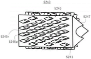
Fig. 9 is a view showing that a plurality of projections are formed by intersections of a plurality of spiral flow paths and a plurality of circular flow paths in the main body portion of the 2 nd inner structure.
Fig. 10 is a perspective plan view of a fluid supply tube according to embodiment 2 of the fluid characteristics changing apparatus of the present invention.
Fig. 11 is an exploded sectional view of the fluid supply tube of fig. 10.
Fig. 12 is a side view (a) and a 3-dimensional perspective view (B) of the vortex generating portion on the upstream side of the 1 st inner structure of embodiment 2.
Fig. 13 is a top sectional view of the 1 st inner structure of embodiment 2.
Fig. 14 is an exploded cross-sectional view of a fluid supply tube of embodiment 3 of the fluid characteristic changing apparatus of the present invention.
Fig. 15 is a top sectional view of the 1 st inner structure of embodiment 3.
Fig. 16 is a perspective plan view of a fluid supply tube according to embodiment 4 of the fluid characteristics changing apparatus of the present invention.
Fig. 17 is a 3-dimensional exploded perspective view of the fluid supply tube of fig. 16.
Fig. 18 is an external view of the 2 nd inner structure of embodiment 4.
Fig. 19 is a perspective plan view of a fluid supply tube according to embodiment 5 of the fluid characteristics changing apparatus of the present invention.
Fig. 20 is a 3-dimensional exploded perspective view of the fluid supply tube of fig. 19.
Fig. 21 is an external view of the 2 nd inner structure of embodiment 5.
Fig. 22 is a 3-dimensional exploded perspective view of a fluid supply tube according to embodiment 6 of the fluid characteristic changing apparatus of the present invention.
Fig. 23 is an exploded sectional view of the fluid supply pipe of embodiment 6.
Fig. 24 is an exploded cross-sectional view of a modification of the fluid supply pipe according to embodiment 6.
Fig. 25 is a 3-dimensional exploded perspective view of a fluid supply tube according to embodiment 7 of the fluid characteristic changing apparatus of the present invention.
Fig. 26 is an exploded sectional view of the fluid supply pipe of embodiment 7.
Fig. 27 is an external perspective view of the 1 st inner structure of embodiment 7.
Fig. 28 is a 3-dimensional sectional view of the 1 st inner structure of embodiment 7.
Fig. 29 is a 3-dimensional exploded perspective view of a fluid supply tube according to embodiment 8 of the fluid characteristic changing apparatus of the present invention.
Fig. 30 is an exploded sectional view of the fluid supply pipe of embodiment 8.
Detailed Description
A utilization device using the fluid characteristics changing device S of the present invention is shown below. 1 is a tank (tank) for storing a fluid (e.g., water). The fluid in the water tank 1 is sucked up by the pump 2 and supplied to the fluid property changing device S through the pipe. The fluid property changing device S is not particularly shown except for supplying the fluid (1 st fluid) from the water tank 1, but sucks the 2 nd fluid as necessary, changes the fluid property, and supplies the fluid to the target device 4 through the valve 3. When the 2 nd fluid is air, only the outside air may be taken in the fluid property changing device S. For example, when the 1 st fluid from the water tank 1 is water and the 2 nd fluid is air, in the fluid property changing device S, the sucked air is stirred, diffused, sheared, or the like while the ultrafine bubbles (the inside of the bubbles is mainly vaporized water) are directly generated, and thereby a large amount of microbubbles (a part of which may become ultrafine bubbles) mainly containing air are generated inside the bubbles. Alternatively, the fluid property changing device S may generate both ultrafine bubbles and microbubbles only with the 1 st fluid without taking in the 2 nd fluid. That is, the fluid property changing device S of the present invention can generate fine bubbles by boiling and vaporizing the fluid itself by reducing the pressure, or by reducing the pressure of the gas dissolved in the fluid at normal temperature and precipitating the gas. By doing so, in the fluid characteristic changing device S, the ultrafine bubbles can be generated together with the generation of the microbubbles, and the fluid containing the fine bubbles of various sizes can be used by the device. Further, the fluid property changing device S can also mix, or stir, diffuse, or shear 2 kinds of fluids (liquids with each other, liquids with gases, gases with each other, or gas-liquid mixed fluids with each other).
Based on the outputs of the sensor 5 and the sensor 6, the control device 7 controls the opening and closing of the valve 3, and the control state is displayed on the display panel 8 to the operator, the sensor 5 detects the state (water temperature, etc.) of the 1 st fluid in the water tank 1, and the sensor 6 detects the state (flow rate, pressure, etc.) of the fluid passing through the fluid characteristic changing device S. The fluid passing through the valve 3 is supplied to the target device 4. In the target equipment 4, when the supply fluid is not consumed and the fluid is recycled, the fluid used in the target equipment 4 is returned to the water tank 1 after foreign substances and impurities are filtered (after temperature recovery in some cases) through a filter 9 (a cooler (Chiller) in some cases) or the like.
The fluid from the fluid property changing device S of the present invention is used for various utilization devices. For example, the working unit is cooled or cleaned by discharging the fluid from the fluid property changing device S from the nozzle to the workpiece or the tool such as the grinding wheel or the drill. Alternatively, the utilization apparatus can be used as a cleaning system for a production line (particularly, precision equipment) in a factory. In this way, the fluid supplied from the fluid characteristic changing device S functions as a coolant and a cleaning agent in the target equipment 4. That is, since the liquid containing fine bubbles reduces the surface tension of the fluid and increases the permeability, the fluid spreads to the fine portion, thereby improving the cooling effect and the cleaning ability. In the cavitation phenomenon described later, when the air pressure in the liquid becomes a saturated vapor pressure or less, bubbles are generated by water vapor in the case where the liquid is water. The bubble is formed by the negative pressure and will of course be destroyed at high pressure, at which point a large impact will occur. The impact is applied to washing, thereby improving the washing ability. Similarly, the utilization apparatus can be used as a cleaning apparatus for warehouses, containers, and facilities. Further, ozone is mixed as a 2 nd fluid with water from the water tank 1, the characteristic of the mixture is changed to ozone fine bubble water in the fluid characteristic changing device S, and the ozone fine bubble water is discharged to a target product in the target device 4. If this is done, deodorizing, decolorizing, and sterilizing effects can be obtained. Ozone is decomposed into oxygen molecules, and OH radicals and the like are generated in the process, whereby the sterilization performance is improved. Therefore, the supply fluid from the fluid property changing device S is used as a bactericide, for example.
Further, as a utilization device including the target device 4, there are fluid systems such as washing, bathing, washing, and cleansing in the home, and a cleansing effect can be expected. In this case, the water tank 1 is not required, and tap water (the 1 st fluid) supplied from a tap water pipe can be directly passed through the fluid property changing device S (the 2 nd fluid is air). Similarly, the present invention can be applied to a fluid system using tap water directly in a factory, an office, or a store. Alternatively, oxygen can be mixed as the 2 nd fluid with water from the water tank 1, and the characteristics thereof can be changed to oxygen fine bubble water in the fluid characteristic changing device S, and the fluid system can be applied to water treatment in agriculture, the aquatic product field, or other fields. The liquid containing the fine bubbles can be absorbed by plants or fish, thereby accelerating the growth rate. In addition, it is also used for washing foodstuffs such as rice or crops, fresh fish, etc. Further, the present invention can be applied to a water treatment system for purification of ground water, well water, polluted water, or the like. Hydrogen gas, carbon dioxide gas, or another gas is mixed as the 2 nd fluid with water from the water tank 1, and the characteristics of the mixture are changed in the fluid characteristic changing device S into fine bubble water having hydrogen gas fine bubble water, carbon dioxide fine bubble water, or other characteristics, or into various functional waters, so that the fluid characteristic changing device can be used for various purposes.
Further, the utilization device including the target equipment 4 can be applied to a fluid system that exchanges heat generated by various kinds of equipment, and the fluid from the fluid characteristic changing device S can be supplied to the heat exchanger to be cooled or heated. The fluid (including fine bubbles, and the effect of temperature change can be expected) from the fluid characteristic changing device S is passed through the pipe in the heat exchanger in the target equipment 4. In the target equipment 4, the fluid passing through the heat exchanger is returned to the original temperature in a cooler not shown, and is circulated and supplied to the water tank 1. By doing so, the fluid supplied to the target apparatus 4 functions as a heat conductive agent that realizes cooling or heating of the target apparatus.
In the case of a fluid system that consumes a specific fluid (without circulating the fluid), the fluid is appropriately supplied to the water tank 1 and used. Such target devices are various manufacturing and production lines, and the fluid from the fluid property changing device S can be used for manufacturing and producing various articles (food, medicine, emulsion fuel, and the like).
In the present invention, the fluid property changing device S includes the 1 st and 2 nd inner structures or one inner structure including an inner structure and an outer structure for changing the property of the supplied fluid, but the inner structure also includes an inner structure in which fine bubbles (microbubbles or microbubbles) are generated in the fluid or a structure which is considered to change the property of the fluid by stirring, diffusing, or shearing the fluid, and which changes the connection structure between molecules of the fluid. Further, a configuration in which a plurality of such internal structures are arranged in series or in parallel may be employed as the fluid characteristic changing apparatus S.
(embodiment 1)
Fig. 2 is a 3-dimensional perspective view of a fluid supply tube 1100 according to an embodiment of a fluid characteristic changing apparatus S of the present invention, fig. 3 is a perspective plan view of the fluid supply tube 1100 when the internal components are housed and fixed, fig. 4 is a 3-dimensional exploded perspective view of the fluid supply tube 1100, and fig. 5 is an exploded sectional view of the fluid supply tube 1100. As shown in these drawings, the fluid supply pipe 1100 includes a pipe main body 110, a 1 st inner structural body 140 and a 2 nd inner structural body 240 constituting inner structural bodies. The 2 nd inner structure 240 has a hollow tube structure. In fig. 2, a fluid flows from the inlet 111 toward the outlet 112. The inlet 111 and the outlet 112 have the same diameter and are concentric.
The tube main body 110 functions as a container for containing the 2 nd inner structure 240, and the 1 st inner structure 140 is disposed in the space inside the 2 nd inner structure 240. The tube main body 110 is composed of an inflow side member 120 and an outflow side member 130. The inflow side member 120 and the outflow side member 130 have the form of cylindrical hollow tubes. The inflow member 120 has an inflow port 111 having a predetermined diameter at one end portion, and a female screw 121 formed by screwing an inner peripheral surface of the female screw 121 is provided on the other end portion side for connection with the outflow member 130. On the side of the inlet 111, a coupling portion is formed, and the inflow member 120 and the upstream joint portion are coupled to each other by a female screw 122 formed on an inner peripheral surface of the coupling portion and a male screw formed on an outer peripheral surface of an end portion of the upstream joint portion, not shown. As shown in fig. 3, the inner diameter of the inlet 111 is smaller than the diameter of the female screw 121, and a tapered portion 123 corresponding to the difference in diameter is formed from the terminal end of the female screw 122 to the start end of the female screw 121.
The outflow member 130 has an outflow port 112 having a predetermined diameter at one end portion, and a male screw 132 for connection to the inflow member 120 at the other end portion, and the male screw 132 is formed by screwing the outer peripheral surface. The diameter of the outer peripheral surface of the male screw 132 of the outlet side member 130 is the same as the inner diameter of the female screw 121 of the inlet side member 120. A connection portion is formed on one side of the outflow port 112, and the connection portion is connected to a downstream joint portion, not shown. For example, the outflow member 130 is coupled to the joint by screwing a female screw 133 formed on an inner peripheral surface of the coupling portion to a male screw formed on an outer peripheral surface of an end portion of the joint. The pipe main body 110 is formed by coupling the inflow member 120 and the outflow member 130 by screwing the female screw 121 on the inner circumferential surface of one end of the inflow member 120 and the male screw 132 on the outer circumferential surface of one end of the outflow member 130. As shown in fig. 3, since the inner diameter of the pipe in which the female screw 132 is implemented is larger than the diameter of the outlet 112, a tapered portion 134 is provided on the downstream side of the outlet side member 130, and the downstream side end portion is connected to the upstream side end portion of the female screw 133.
The above-described configuration of the tube main body 110 is only one embodiment, and the present invention is not limited to the above-described configuration. For example, the connection between the inflow side member 120 and the outflow side member 130 is not limited to the screw connection, and any method known to those skilled in the art for connecting mechanical parts can be applied. The forms of the inflow side member 120 and the outflow side member 130 are not limited to the form of fig. 2, and can be arbitrarily selected by a designer or changed according to the use of the fluid supply pipe 1100. The inflow member 120 and the outflow member 130 are made of metal such as steel, or nonmetal such as plastic or resin. This is the same in other embodiments described below.
Referring to fig. 2 to 5 together, it can be understood that the fluid supply pipe 1100 is constructed as follows: the 1 st inner structure 140 is inserted and fixed into the hollow cavity of the cylindrical shaft body of the 2 nd inner structure 240, and then is received in the outflow member 130, and then the male screw 132 on the outer peripheral surface of the outflow member 130 is coupled to the female screw 121 on the inner peripheral surface of the inflow member 120. In fig. 3, the 1 st inner structure 140 may be completely accommodated in the 2 nd inner structure 240, and the 1 st inner structure 140 may have a length protruding from the upstream end and/or the downstream end of the 2 nd inner structure 240. This is also the same in other embodiments below embodiment 2. As shown in fig. 3, the step at the downstream end of the internal cavity portion of the 2 nd inner structure 240 (located on the upstream side of the guide portion 247 described later) serves as a stopper for positioning the 1 st inner structure 140 with respect to the 2 nd inner structure 240 when it is disposed, and the step at the upstream end of the tapered portion 134 of the outflow-side member 130 serves as a stopper for positioning the 2 nd inner structure 240 with respect to the tube main body 110 when it is disposed. In addition, it is also possible to prepare a special fixing member and a special supporting member, fix or support the 1 st inner structure 140 to the inner space of the 2 nd inner structure 240, and fix or support the 2 nd inner structure 240 to the inner space of the tube main body 110. This is also the same in other embodiments described below.
The 1 st inner structure 140 is formed by a method of processing a cylindrical member made of metal such as steel, a method of molding plastic (including a method of injection molding), or the like, for example. The outer diameter thereof is equal to or slightly smaller than the inner diameter of a cylindrical space (cavity) of a hollow shaft body (cylindrical tube body) of the 2 nd inner structure 240 to be described later, and the 1 st inner structure 140 has a cylindrical shape that is accommodated in the cylindrical space of the 2 nd inner structure 240. As shown in fig. 7, the inner space has a vortex generating portion 141 on the upstream side and a flow property imparting portion 142 on the downstream side. The vortex flow generating portion 141 and the flow characteristic imparting portion 142 may be formed separately or integrally, and may be formed by machining the inside of a cylindrical member by cutting, turning, or grinding, for example, individually or in combination. Alternatively, the printing material may be formed by 3-dimensional printing of a metal or resin material using a 3D printer.
The eddy current generating portion 141 is provided near the opening on the upstream side. Specifically, in the vortex flow generating portion 141, a plurality of grooves that change the flow of the fluid at a specific angle are formed in the upstream inner wall surface of the pipe body. Specifically, as shown in fig. 6 (a), 8 grooves each having a substantially semicircular cross section are formed at a specific angle in the oblique direction from the end surface thereof as shown in fig. 6 (B). That is, the grooves 141-1 to 141-8 are formed at 45 degree intervals in the end face thereof, and have inclination obliquely to the right as going downstream. The number of the grooves, the shape of the grooves, and the specific inclination angle can be appropriately selected, and are not limited to this embodiment. With this configuration of the vortex flow generating unit 141, the fluid supplied to the 1 st inner structure 140 becomes a rightward swirling vortex flow in the upstream portion. Since the eddy current can be generated only by forming such a plurality of grooves, the processing is extremely simple.
The flow characteristic imparting portion 142 on the downstream side of the 1 st inner structure 140 has an inner cavity having a venturi shape. That is, the reduced diameter portion 142-1 having a sharply reduced inner diameter, the throttle portion 142-2 having a relatively small inner diameter connected thereto, and the enlarged diameter portion 142-3 having a sharply enlarged inner diameter are formed in the same center shape. As one configuration example, the distance in the flow direction of the fluid in the diameter-reduced portion 142-1 is shorter than the distance in the flow direction of the fluid in the diameter-enlarged portion 142-3. The maximum radius of the reduced diameter portion 142-1 is equal to or substantially equal to the maximum radius of the enlarged diameter portion 142-3. Of course, the shape of the venturi tube in the internal cavity can be changed as appropriate. The velocity of the fluid (actually, the fluid flows as a vortex (a spiral flow)) becomes maximum at the throttle portion 142-2 due to a sharp change in the inner diameter of the inner cavity, and the static pressure of the fluid sharply decreases due to the bernoulli equation with respect to the static pressure or the static pressure. The relationship of pressure, velocity, and position energy in a state where no external energy is applied to the fluid can be expressed as the Bernoulli equation (Bernoulli's solution) as follows.
[ formula 1 ]

Here, P is a pressure at a point in the streamline, i.e., a static pressure, ρ is a density of the fluid, V is a velocity of the flow at the point, g is a gravitational acceleration, h is a height of the point with respect to a reference plane, and K is a constant. The bernoulli's theorem expressed as the above equation applies the law of conservation of energy to a fluid, and the 1 st term corresponds to energy of pressure (static pressure), the 2 nd term corresponds to kinetic energy (dynamic pressure), and the 3 rd term corresponds to positional energy, and explains the following cases: for a flowing fluid, the sum of the energies of all the forms is always constant on the flow line. According to Bernoulli's theorem, the fluid velocity is relatively slow and the static pressure is relatively high at the upstream of the reduced diameter portion 142-1. In contrast, the fluid velocity becomes higher and the static pressure becomes lower as it goes downstream of the reduced diameter portion 142-1 having a smaller cross-sectional area. At the throttle portion 142-2, the velocity of the fluid becomes maximum, and the static pressure becomes minimum.
In the case of a liquid, the boiling point will drop as the gas pressure drops, so according to Boyle-Charles' law, vaporization of the liquid will start when the lower static pressure reaches the saturated vapor pressure of the liquid. As described above, the phenomenon in which the static pressure P becomes lower than the saturated vapor pressure Pv (3000 to 4000Pa in the case of water) in an extremely short time at substantially the same temperature and the liquid is rapidly vaporized is referred to as cavitation (cavitation). The venturi cavity shape induces such cavitation. The cavitation phenomenon causes the liquid to boil with nuclei of fine bubbles of 100 μm or less present in the liquid, or causes a large number of small bubbles to be generated due to dissociation of dissolved gas. At this time, there is a possibility that a part of the bubbles is ultrafine bubbles, but microbubbles are mainly generated.
In the case where the fluid property changing device S (see fig. 1) is configured to mix gas as the 2 nd fluid into the liquid as the 1 st fluid, similarly, in the flow property imparting portion 142, the static pressure of the gas is lowered at the throttle portion 142-2, the bubbles are expanded and expanded, and the flow velocity is lowered and the pressure is increased due to the rapid expansion change of the inner diameter of the diameter-enlarged portion 142-3, and the large-sized bubbles are pressurized, and are crushed, broken, and refined, and mainly micro-bubbles are generated.
As described above, a part of the fluid supplied from the inlet 111 of the tube main body 110 is supplied from the upstream opening of the 1 st inner structure 140 and turns right into a swirling fluid in the upstream vortex generating portion 141, and when the internal cavity in the venturi tube shape of the downstream flow characteristic imparting portion 142 passes as a swirling flow from the downstream flow characteristic imparting portion 142, the speed thereof changes, and after the static pressure sharply decreases in the reduced diameter portion 142-1, the static pressure becomes the lowest static pressure in the throttle portion 142-3, and conversely, the static pressure sharply increases in the enlarged diameter portion 142-3, and thus fine bubbles are generated or the mixed gas becomes fine bubbles such as microbubbles. Then, the fluid containing the fine bubbles flows out from the most downstream opening end of the diameter-enlarged portion 142-3 in the 1 st inner structure 140.
On the other hand, as shown in fig. 8, the 2 nd inner structure 240 of the present embodiment has a hollow shaft body inside, and a head portion 243, a body portion 245, and a guide portion 247 are integrally formed on a shaft portion 241 from the upstream side to the downstream side. The head portion 243, the body portion 245, and the guide portion 247 are formed by machining a cylindrical tubular member made of metal such as steel by cutting, turning, or grinding, for example, individually or in combination. Or by a method of molding plastic (including a method of injection molding). Alternatively, the material may be 3-dimensionally printed from a metal or resin material by a 3D printer.
More specifically, the head portion 243 is a portion that generates a vortex flow (spiral flow) with respect to the fluid, and includes a shaft portion 241 and fins 243-1 to 243-4, the shaft portion 241 has a constant diameter along the longitudinal direction when the 2 nd inner structure 240 is housed in the tube main body 110, and the fins 243-1 to 243-4 are formed in 4 spiral shapes. As shown in fig. 8 (a), the tips of the vanes 243-1 to 243-4 are formed on the outer peripheral surface of the space corresponding to the head portion 243 of the shaft portion 241 in a clockwise spiral manner at predetermined intervals while being shifted by 90 degrees from each other in the circumferential direction of the shaft portion 241. In the present embodiment, the number of blades is set to 4, but the present invention is not limited to this embodiment, and the number of blades may be plural, and preferably 3 or more. By doing so, the head 243 creates a clockwise vortex for the fluid. In addition, as long as the form of the vanes 243-1 to 243-4 for generating the vortex flow of the head 243 is a form capable of inducing the vortex flow while the fluid passes between the vanes, the angle, thickness, and other shapes of the vanes are not particularly limited. In the present embodiment, when the 2 nd inner structure 240 is housed in the tube main body 110, the head 243 has an outer diameter close to the wall surface of the inner space of the outflow-side member 130 of the tube main body 110. That is, the maximum outer diameter of the outer surface of the head 243 is equal to or slightly smaller than the inner diameter of the tube body 110.
The body portion 245 is formed on the downstream side of the head portion 243, and includes a shaft portion 241 and a plurality of projecting portions (convex portions) 245p, the shaft portion 241 having a cylindrical cross section and a constant diameter, and the plurality of projecting portions (convex portions) 245p being formed in a mesh shape projecting from the outer peripheral surface of the shaft portion 241. The protrusion 245p has a substantially rhombic cross section taken horizontally. In the present embodiment, the diameter of the shaft portion 241 of the body portion 245 is the same as the diameter of the head portion 243. When the fluid flows from the head portion 243 to the body portion 245, the cross-sectional area of the flow path is rapidly reduced, and the flow characteristics of the fluid are changed.
Fig. 9 shows an example of a method for forming the projection 245p and the flow path 245r according to the present embodiment. A plurality of lines (14 circular closed flow paths, for example, that flow in parallel) having a constant interval in a direction of 90 degrees with respect to the longitudinal direction (the left-right direction in the drawing) of the cylindrical shaft member and a plurality of lines (a plurality of spiral flow paths, for example, that flow in a spiral shape of 8) having a constant interval inclined at a predetermined angle (for example, 60 degrees) with respect to the longitudinal direction are intersected, and machining such as cutting is performed while skipping between the lines in the direction of 90 degrees once, and machining such as cutting is performed while skipping between the lines that are inclined once. By doing so, the plurality of protrusions 245p protruding from the outer peripheral surface of the shaft portion 241 are regularly formed one above the other in the vertical direction (circumferential direction) and the horizontal direction (longitudinal direction of the shaft portion 241). As described above, the flow paths 245r are formed between the respective projections 245p. In the present embodiment, when the inner structure 240 is housed in the tube main body 110, the main body 245 has an outer diameter close to the wall surface of the cylindrical inner space of the outflow-side member 130 of the tube main body 110 (that is, close to the wall surface where the top surface (upper surface) of the protrusion 245p contacts). The plurality of projections 245p may have various shapes, such as a triangle, a polygon, and other shapes, and may be an air foil (air foil) type (airfoil type) disclosed in WO2014/204399, or a notch (notch) type (notch type) modified to japanese unexamined patent publication 2016-536139, for example. The arrangement can be appropriately changed (angle, width, etc.) according to fig. 9. For example, the size of the projection may be increased on the upstream side and decreased on the downstream side. The selection and modification of such shapes and arrangements can be applied to other embodiments as well.
In the present embodiment, a guide portion 247 is provided in the center portion of the truncated dome shape whose side surface is shown in fig. 8 (B) on the downstream side of the main body portion 245, and a hole connecting the downstream-side opening end of the 1 st inner structure 140 in the guide portion 247 is opened. The fluid guided to the center by the guide portion 247 is ejected through the outlet port 112 of the tube main body 110. The shape of the guide portion 247 is not limited to the truncated dome shape, and may be a truncated cone shape, a truncated pyramid shape, or the like.
A part of the fluid flowing in through the inlet 111 of the tube main body 110 passes through and travels between the inner wall surface of the inlet side member 120 and the 4 vanes 243-1 to 243-4 of the head 243 formed in a spiral shape. As a result, the fluid is strongly swirled by the vanes of the head portion 243 and is sent to the main body portion 245. The fluid passes through a plurality of narrow flow passages 245r between the plurality of projections 45p having a substantially rhombic horizontal cross section of the main body portion 245. Specifically, among the flow paths 245r, for example, 8 spiral flow paths have a relatively rapid flow, and 14 circular closed flow paths have a relatively slow flow. The spiral flow path and the annular closed flow path form a cross flow path which crosses each other, and the fluid travels downstream as a whole while repeatedly colliding at the crossing position. As a result, turbulence is generated in the fluid and a plurality of minute vortices are generated. By such a phenomenon, mixing and diffusion of the fluid are induced. The above-described structure of the main body portion 245 is also useful for mixing two or more fluids having different properties.
Further, the 2 nd inner structure 240 has a structure in which a fluid flows from an upstream side (head portion 243) having a large cross-sectional area to a downstream side (flow paths 245r formed between the plurality of projecting portions 245p of the body portion 245) having a small cross-sectional area. This structure is represented by the bernoulli equation described above. In the case where the fluid is a liquid, cavitation is induced. Due to the cavitation phenomenon, the liquid boils with nuclei of fine bubbles of 100 μm or less present in the liquid, or a large number of small bubbles are generated due to dissociation of dissolved gas. That is, fine bubbles including a plurality of microbubbles and ultrafine bubbles are generated in the process of the fluid passing through the flow characteristic imparting unit 245.
In addition, in the case where the fluid is water, 1 water molecule forms a hydrogen bond with the other 4 water molecules, but it is not easy to break the hydrogen bond network. Therefore, water has a very high boiling point and a very high melting point and exhibits a high viscosity as compared with other liquids that do not form hydrogen bonds. Water is frequently used as cooling water in the field of machining apparatuses and machine tools because of its high boiling point property, which provides an excellent cooling effect, but has the following problems: the size of water molecules is large, and the permeability and lubricity to the processing site are poor. Therefore, in general, special lubricating oil (e.g., cutting oil) other than water is often used alone or in combination with water. However, when the fluid supply pipe 1100 is used, vaporization of water occurs due to the cavitation phenomenon described above, and as a result, it is considered that the hydrogen bonding network of water is broken. In addition, the fine bubbles (in particular, ultrafine bubbles) generated by vaporization improve the permeability and lubricity of the fluid (water). The result of the increased permeability is an increased cooling efficiency.
The fluid containing the fine bubbles passing through the body portion 245 is guided by the guide portion 247 and flows toward the end of the 2 nd inner structure 240. By doing so, the fluid (mainly including the ultra fine bubbles) passing through the flow path between the 2 nd inner structure 240 and the inner wall of the tube main body 110 merges with the fluid (mainly including the micro bubbles) passing through the inner flow path of the 1 st inner structure 140 at the downstream of the tube main body 110, and is output from the outlet port 112 of the tube main body 110 to the outside.
In the above configuration example, the vortex flow generating portion 141 of the 1 st inner structural body 140 and the head portion 243 of the 2 nd inner structural body 240 generate a clockwise vortex flow (swirling flow), but a counterclockwise vortex flow (swirling flow) may be generated together. The same applies to other embodiments described below.
(embodiment 2)
Next, a fluid supply tube according to embodiment 2 of the fluid characteristic changing apparatus S of the present invention will be described. Fig. 10 is a perspective top view of the fluid supply tube 2100, and fig. 11 is an exploded sectional view of the fluid supply tube 2100. The 2 nd embodiment is different from the 1 st embodiment only in the configuration of the upstream portion vortex generating member of the 1 st inner structure, and the same reference numerals are given to the same portions as those of the 1 st embodiment, and the description thereof is omitted. As shown in the drawing, the present embodiment is different from embodiment 1 only in the eddy current generating portion 2141 of the 1 st inner structure 2140. That is, the vortex flow generating portion 2141 provided in the vicinity of the opening portion on the upstream side is configured by a plurality of fins protruding from the inner wall surface of the cylindrical tube body. In the present embodiment, the number of blades is 3, and may be 2 or 4 or more. In the present embodiment, the wings 2141-1 to 2141-3 have tips shifted by 120 degrees in the circumferential direction as shown in fig. 12 (a), for example, in the shape of a spiral wing or feather having a length in the downstream direction (for example, half a circumference around the side surface of a cylindrical tube) as shown in fig. B, to generate a right-handed (clockwise) vortex. The number of the plurality of blades is related to an angle at which the tip end deviates from the circumferential direction of the shaft portion. For example, the angle is 90 degrees in the case of 4 pieces, and 72 degrees in the case of 5 pieces. The angle, thickness and other shapes of the wings are not particularly limited as long as the shape of the wings is a shape that can induce a vortex during the passage of the fluid between the wings.
In embodiment 2, a part of the fluid supplied from the inlet 111 of the tube main body 2110 is supplied from the opening portion on the upstream side of the 1 st inner structure 2140, and becomes a fluid swirling rightward in the vortex generating portion 141 on the upstream side, and when an inner cavity in the venturi tube shape of the downstream flow characteristic imparting portion 142 passes as a swirling flow from the downstream side, the velocity thereof changes, and after the static pressure sharply decreases at the reduced diameter portion 142-1, the static pressure becomes the lowest at the throttle portion 142-3, and conversely, the static pressure sharply increases at the enlarged diameter portion 142-3, and therefore fine bubbles are generated, or the mixed gas becomes fine bubbles such as microbubbles. Then, the fluid containing the fine bubbles flows out from the most downstream opening end of the diameter-enlarged portion 142-3 in the 1 st inner structure 2140. Then, the fluid containing the fine bubbles flows out from the most downstream opening end of the diameter-enlarged portion 142-3 in the 1 st inner structure 2140. The fluid (mainly including the ultrafine bubbles) that has passed through the flow path between the 2 nd inner structure 240 and the inner wall of the tube main body 110 merges downstream of the tube main body 110, and is output to the outside from the outlet 112 of the tube main body 110.
In the present embodiment, the vortex flow generating portion 2141 of the 1 st inner structural body 2140 and the head portion 243 of the 2 nd inner structural body 240 are configured to generate a clockwise vortex flow (swirling flow), but a counterclockwise vortex flow (swirling flow) may be generated together. The vortex generating portion 2141 of the 1 st inner structure 2140 can be employed in other embodiments described below.
(embodiment 3)
Next, a fluid supply tube according to embodiment 3 of the fluid characteristic changing apparatus S of the present invention will be described. Fig. 14 is an exploded cross-sectional view of the fluid supply tube 3100. Embodiment 3 differs from embodiments 1 and 2 only in that there is no vortex generating member in the upstream portion. The same reference numerals are given to the same portions as those in embodiment 1 and embodiment 2, and the description thereof is omitted.
First inner structure 3140 is provided with flow characteristic imparting portion 3142 and has an inner cavity having a venturi shape. That is, the reduced diameter portion 3142-1 having a sharply reduced inner diameter, the throttling portion 3142-2 having a relatively small inner diameter connected thereto, and the enlarged diameter portion 3142-3 having a sharply enlarged inner diameter are formed in the same center shape. As one configuration example, the distance in the fluid flow direction of the diameter-reduced portion 3142-1 is shorter than the distance in the fluid flow direction of the diameter-enlarged portion 3142-3. The maximum radius of the reduced diameter portion 3142-1 is equal to or substantially equal to the maximum radius of the enlarged diameter portion 3142-3. The shape of the venturi tube in the internal cavity can be changed as appropriate. The velocity of the substantially straight fluid (in some China, a vortex is generated by a turbulent flow) is maximized at the throttle portion 3142-2 due to a rapid change in the inner diameter of the internal cavity, and the static pressure of the fluid is rapidly reduced according to the bernoulli equation. Further, the static pressure is suddenly increased at the enlarged diameter portion 3142-3, and therefore, fine bubbles are generated or the mixed gas becomes fine bubbles such as microbubbles. Then, the fluid containing the fine bubbles flows out from the most downstream opening end of the diameter-enlarged portion 3142-3 in the 1 st inner structure 3140. In the following embodiments, the 1 st inner structure 3140 having no vortex generating portion may be employed.
(embodiment 4)
Next, a fluid supply tube according to embodiment 4 of the fluid characteristic changing apparatus S of the present invention will be described. Fig. 16 is a perspective plan view of the fluid supply tube 4100, and fig. 17 is an exploded 3-dimensional external perspective view of the fluid supply tube 4100. Embodiment 4 differs only in the configuration of the internal structure of embodiment 1 and embodiment 2, and the same reference numerals are given to the same portions as embodiment 1, and the description thereof is omitted. As shown in fig. 18, in the present embodiment, the hollow 2 nd inner structure 4240 is a hollow circular shaft body, and has a main body portion 4245 on the outer surface, and the main body portion 4245 is provided with a plurality of protrusions 4245p in a net shape. Unlike embodiment 1, the head is not provided.
The main body 4245 includes: a shaft portion 4241 having a cylindrical cross section and a constant diameter; and a plurality of protrusions (protrusions) 4245p having a substantially rhombic shape in cross section, which are formed in a net shape protruding from the outer peripheral surface of the shaft portion 421. In embodiment 4, the side (side edge) of the connecting projection 4245p having a substantially rhombic cross section and an obtuse vertex is formed to reach the front with respect to the flow (the direction from the left side to the right side in fig. 18), and the fluid flows in a manner of being divided into left and right sides by the 2 sides sandwiching the obtuse angle. The fluid travels in 2 directions of obliquely upward right and obliquely downward right in fig. 18, and repeatedly collides with and is mixed with the fluid from the other projection 4245p that also travels obliquely upward right and obliquely downward right. In this way, the fluid flows through the intersecting flow path 4245r and flows downstream. In fig. 18, a plurality of protrusions 4245p protruding from the outer peripheral surface of the shaft portion 4241 are regularly formed by cutting and the like from the upper and lower sides (circumferential direction) and the left and right sides (longitudinal direction of the shaft portion 4241) one by one, respectively, by skipping a plurality of lines inclined in the right oblique upper direction while performing the cutting and the like once each over a plurality of lines having a constant interval, from 180 degrees with respect to the longitudinal direction (left and right direction of the drawing) of the cylindrical shaft member, and by making an obtuse angle (for example, 140 degrees) of a rhombus, and making the inclination (for example, 20 degrees) of the angle common to the right oblique lower direction of the drawing.
In the present embodiment, the body portion 4245 has an outer diameter close to the wall surface of the cylindrical internal space of the outflow member 130 of the tube main body 110 (i.e., close to the extent that the top surface (upper surface) of the projection 4245p contacts the wall surface) when the inner structure 4240 is accommodated in the tube main body 110. In addition, the top surface is a portion of the outer surface of the original cylinder, with rounded corners. The shape and arrangement of the plurality of protrusions 4245p may be appropriately changed as shown in fig. 18.
In the present embodiment, a guide portion 4247 is provided downstream of the body portion 4245. The guide portions 4247 are 8 protrusions having inclined surfaces facing the center of the shaft body, and guide the fluid toward the center of the shaft body. The fluid is discharged through the outlet 112 of the tube main body 110. The number and shape of the guide portions 4247 are not limited to those shown in the drawings.
A part of the fluid flowing in through the inlet 111 of the tube main body 110 passes through a plurality of narrow flow passages 4245r between a plurality of protrusions 4245p having a substantially rhombic cross section of the main body 4245. Specifically, the flow passage 4245r is an intersecting flow passage that intersects with each other, and the fluid travels downstream as a whole while repeatedly colliding with each other at the intersecting position. As a result, turbulence is generated in the fluid and a plurality of minute vortices are generated. Alternatively, a triggering phenomenon in which the fluid is alternately switched may occur, and due to this phenomenon, mixing and diffusion of the fluid may be induced. The above-described structure of the body portion 4245 is also useful for mixing two or more fluids having different properties.
In the present embodiment, regarding the fluid supplied from the upstream, the cross-sectional area of the flow passage 4245r is rapidly reduced in the main body portion 4245, and the flow characteristics of the fluid are changed. This is the same as in embodiments 1 to 3. That is, in the flow path 4245r having a narrow cross section where the 2 nd inner structure 4245 intersects, the liquid boils around the nuclei of fine bubbles of 100 μm or less present in the liquid due to the cavitation phenomenon, or a large number of small bubbles are generated due to the release of the dissolved gas. That is, fine bubbles (fine bubbles) including a large number of microbubbles and ultrafine bubbles are generated in the process of the fluid passing through the flow property imparting unit 4245.
(embodiment 5)
Next, a fluid supply tube according to embodiment 5 of the fluid characteristic changing apparatus S of the present invention will be described. Fig. 19 is a perspective top view of the fluid supply tube 5100, and fig. 20 is an exploded 3-dimensional external perspective view of the fluid supply tube 5100. Embodiment 5 differs only in the configuration of the internal structure of embodiment 2 from that of the other embodiment, and the same reference numerals are given to the same portions as those of the other embodiment, and the description thereof is omitted. As shown in fig. 20, in the present embodiment, the hollow 2 nd internal structure 5240 is a prismatic shaft body, and has a main body portion 5245 on the outer surface, and the main body portion 5245 is provided with a plurality of protrusions 5245p in a net shape. Unlike embodiment 1, the head is not provided. The shaft body of the 2 nd internal structure 5245 has a triangular prism shape and 3 side surfaces. The shaft body may have a quadrangular prism shape or other prism shapes. This also applies to the other embodiments.
In fig. 21, the main body portion 5245 includes: a shaft portion 5241 of a triangular prism shape having a cylindrical cross section; and a plurality of protrusions (convex portions) 5245p formed in a net shape protruding from the outer peripheral surface of the shaft portion 5241. Each of the plurality of projections 5245p has a substantially rhombic cross section. As shown in fig. 21, the sides (side edges) of the connecting protrusions 5245p having substantially rhombic cross sections and acute vertices are formed to extend to the front with respect to the flow (the direction from the left side to the right side in the figure), and the fluid flows in a manner separated from the left and right due to the 2-sided surfaces that sandwich the acute angles. The fluid travels in the diagonally upward and downward right directions, and the other projections 5245p repeatedly collide with and mix with the similarly separated fluid. In this way, the fluid flows through the intersecting flow path 5245r and flows downstream. In fig. 21, a plurality of projections 5245p projecting from the outer peripheral surface are regularly formed in one side surface of the shaft portion 5241 in the vertical direction (circumferential direction) and in the horizontal direction (longitudinal direction of the shaft portion 5241) by cutting or the like while skipping a plurality of lines each having a constant interval in the diagonally downward right direction of the drawing, and by cutting or the like while skipping a space between lines each inclined in the diagonally upward right direction, from 180 degrees with respect to the longitudinal direction (horizontal direction of the drawing) of the triangular prism shaft member, at an acute angle (e.g., 40 degrees) of a rhombus, and at an inclination (e.g., 70 degrees) such that the acute angle becomes half of the angle. The entire main body is formed by performing such a machining process by 3 side surfaces. Since the shaft body before the original processing is cylindrical, the top surfaces (upper surfaces) of the plurality of projections 5245p are rounded outer circumferential surfaces of the original cylinder, and have a shape that is high in the center and low outward in height as a whole.
In the present embodiment, the body portion 5245 has an outer diameter that is close to the wall surface of the cylindrical internal space of the outflow-side member 130 of the tube body 110 (i.e., close to the contact between the top surface (upper surface) of the protrusion 5245p and the wall surface) when the internal structure 5240 is housed in the tube body 110. The shape of the plurality of projections 5245p may take various shapes, and the arrangement thereof may be appropriately changed (angle, width, etc.) according to fig. 21. In particular, when the projections 5245p are arranged in each row while being bent at a slight angle, turbulence is further generated.
In the present embodiment, a guide portion 5247 is provided on the downstream side of the body portion 5245. The guide portion 5247 is a triangular pyramid having a slope toward the center of the shaft body, and the end portion is cut out to connect the internal cavities. The guide portion 5247 guides the fluid toward the center of the shaft body. The fluid is discharged through the outlet 112 of the tube main body 110. The shape of the guide portion 5247 can be appropriately changed according to the prism shape, and is not limited to the shape shown in the drawings.
A part of the fluid flowing in through the inlet 111 of the tube main body 110 passes through the plurality of narrow flow passages 5245r between the plurality of substantially rhombic-cross-section protrusions 5245p provided on each side surface of the main body 5245. Specifically, the flow path 5245r is an intersecting flow path that intersects, and the fluid travels downstream as a whole while repeatedly colliding and mixing at the intersecting position. As a result, turbulence is generated in the fluid and a plurality of minute vortices are generated. Alternatively, a triggering phenomenon in which the fluid is alternately switched may occur, and due to this phenomenon, mixing and diffusion of the fluid may be induced. The above-described structure of the body portion 5245 is also useful for mixing two or more fluids having different properties.
In the present embodiment, regarding the fluid supplied from the upstream, the cross-sectional area of the flow path 5245r in the body portion 5245 is sharply reduced, and the flow characteristics of the fluid are changed. This is the same as in embodiments 1 to 4. That is, in the flow path 5245r having a narrow cross section and intersecting the second inner structure 5240, the liquid boils around the nuclei of fine bubbles of 100 μm or less present in the liquid due to the cavitation phenomenon, or a large number of small bubbles are generated due to the dissociation of the dissolved gas. That is, fine bubbles (fine bubbles) including a plurality of microbubbles and ultrafine bubbles are generated in the process of the fluid passing through the flow characteristic providing portion 5245.
(embodiment 6)
Next, a fluid supply pipe 6100 according to embodiment 6 of the fluid characteristics changing apparatus S of the present invention will be described. Fig. 22 is an exploded 3-dimensional external perspective view of the fluid supply pipe 6100. The pipe body according to embodiment 6 differs from embodiment 1 in that the inflow end portion of the outer surface of the inflow member 6120 has a cylindrical shape with the same diameter and the outflow end portion of the outer surface of the outflow member 6130 has a cylindrical shape with the same diameter. Further, the inner structural body 6140 included in the inside of the tube main body is different in that the 1 st inner structural body 140 of the 1 st embodiment and the 2 nd hollow inner structural body 240 are integrally formed. That is, as shown in fig. 23, the inner structure 6140 according to embodiment 6 has a tubular shape and has an inner structure and an outer structure. The internal structure of the structure inside the pipe body has a vortex generating portion 6141 including a plurality of grooves and a flow characteristic imparting portion 6142 (a reduced diameter portion 6142-1, a throttle portion 6142-2, an enlarged diameter portion 6142-3, and a straight pipe portion 6142-4) which is a hollow venturi tube structure from the upstream, and has the same configuration as that of embodiment 1. An outer structure as an outer structure of the pipe body is formed with a head portion 6143, a body portion 6145, and a guide portion 6147 from upstream. The head portion 6143 has, for example, 4 spiral fins, the body portion includes a plurality of protrusions 6145p formed in a mesh shape, and the guide portion has a truncated dome shape, as in embodiment 1.
That is, in the inner structure 6140 according to the 6 th embodiment, the 1 st inner structure 140 according to the 1 st embodiment is formed integrally with the 2 nd hollow inner structure 240, and the inner structure 6140 is disposed and fixed inside the inflow member 6120 and the outflow member 6130, and when the fluid supply pipe 6100 is manufactured, the 1 st inner structure 140 and the 2 nd inner structure 240 perform the same function and function. The inner structure 6140 can be formed of resin such as plastic or metal such as steel by a 3-dimensional printer. Of course, other manufacturing processes such as molding may be employed. Further, the flow property imparting portion 6142 which is a structure of a hollow venturi tube as an internal structure of the internal structure 6140 preferably generates microbubbles. The main body portion 6145 preferably generates ultrafine bubbles, and the main body portion 6145 is preferably formed with a plurality of protrusions 6145p as an outer structure of the inner structure 6140. Further, the inner structure causes the fluid to flow smoothly as compared with the outer structure, and thus a large amount of fine bubbles can be generated without increasing the flow rate.
Further, the vortex generating portion 6141 of the inner structure 6140 is configured by a plurality of grooves as in embodiment 1, but may be configured by a plurality of fins protruding from the inner wall surface of the cylindrical tube body as in embodiment 2. Further, the configuration may be as in a modification shown in fig. 24. That is, in the fluid supply pipe 6100A in fig. 24, the vortex generating portions 6141 are not formed in the inner structure 6140A, but a straight pipe portion 6146 is formed, and the other portions are the same as in fig. 23 of the embodiment 6, and the same reference numerals are given to the same positions, and description thereof is omitted. That is, in this modification, the vortex generation cannot be expected because there is no vortex generating portion, but it becomes easier to manufacture the internal structure. That is, the internal structure of the internal structure 6140A can be formed in a cutting process, a turning process (boring, etc.), or the like from the upstream side and the downstream side, and a manufacturing process by a 3D printer is not required. Needless to say, this can be achieved by a manufacturing process using a 3D printer. The outer structure of the inner structures 6140 and 6140A may be the same as or different from the body portions 4245 and 5245 of the 4 th and 5 th embodiments. That is, the shape of the plurality of projections 6145p may take various shapes, and for example, may be a triangle, a polygon, or another shape, and for example, may be an air foil (air foil) type (airfoil shape) disclosed in WO2014/204399 or a notch (notch) type (notch type) modified as disclosed in japanese patent No. 2016-536139.
(7 th embodiment)
Next, a fluid supply tube 7100 of a 7 th embodiment of a fluid property changing apparatus S of the present invention will be described. Fig. 25 is an exploded 3-dimensional external perspective view of the fluid supply tube 7100. Fig. 26 is an exploded sectional view of the fluid supply tube 7100. This 7 th embodiment has the inflow side member 6120 and the outflow side member 6130 that are the same as those of the 6 th embodiment. Further, the 1 st inner structural body 7140 included inside is inserted into a hollow cavity of a cylindrical shaft body fixed to the 2 nd inner structural body 7240. As is clear from fig. 27 and 28, the 1 st inner structure 7140 is provided with flow property imparting portions 7142A to 7142C, and these flow property imparting portions 7142A to 7142C are constituted by 3 vortex generating portions 7141A to 7141C and an inner cavity having the shape of a venturi tube located downstream thereof. That is, the flow property imparting portions 7142A to 7142C have the same center shape of a circle, respectively, of a reduced diameter portion 7142-1 having a rapidly decreasing inner diameter, a narrowed diameter portion 7142-2 having a relatively small inner diameter and connected thereto, and an enlarged diameter portion 7142-3 having a rapidly increasing inner diameter. As one configuration example, the distance in the fluid flow direction of the reduced diameter portion 7142-1 is shorter than the distance in the fluid flow direction of the enlarged diameter portion 7142-3. The maximum radius of the reduced diameter portion 7142-1 is the same as or substantially equal to the maximum radius of the enlarged diameter portion 7142-3. Of course, the shape of the venturi tube in the internal cavity can be changed as appropriate. The shapes of the vortex generating portions 7141A to 7141C may be appropriately changed to groove-based or fin-based, or the vortex generating portions 7141A to 7141C may not be provided in order to simplify the manufacturing process. The 2 nd inner structure 7240 into which the 1 st inner structure 7140 is inserted and fixed is the same as the 2 nd inner structure of embodiment 1 or the 2 nd inner structure of another embodiment, and therefore, description thereof is omitted.
As described above, in the present embodiment, particularly when the fluid supply tube 7100 is increased in size and the diameter of the tube is increased in order to increase the flow rate of the fluid, the following possibility exists: the amount of generated micro-bubbles can be maximized by providing a plurality of systems of venturi tubes. In the figure, 3 flow characteristic imparting portions 7142A to 7142C are formed, but the number of the flow characteristic imparting portions can be 2 or more. Therefore, 2 systems, 3 systems, and further, 4 or more systems are all possible. It is needless to say that the flow characteristic providing unit of venturi tubes by a plurality of systems can be applied to the 1 st inner structure of other embodiments.
In embodiment 7, similarly to embodiment 6, the 1 st inner structure 7140 and the 2 nd inner structure 7240 are integrally formed, and the inner structure is in the shape of a pipe body and has an inner structure inside the pipe body and an outer structure outside the pipe body, and the inner structure has a flow characteristic imparting portion of 3 systems, or 2 systems, or 4 or more systems as a structure of a hollow venturi tube, and the outer structure can also have a main body portion in which a plurality of protrusions are formed. In the internal structure, a plurality of fins may be provided that protrude from the inner wall surface of the plurality of grooves or the tubular body that swirl the fluid flowing into the hollow venturi tube.
(embodiment 8)
Fig. 29 and 30 show a fluid supply pipe 8100 according to embodiment 8 of a fluid characteristic changing apparatus S according to the present invention. This is the same as the modification (fig. 24) of embodiment 6, and the inner structure 6140A is the same as embodiment 6, and the description thereof is omitted. The inner structure 6140A is housed and fixed in the tube main body 8130. At an upstream end of an inner surface thereof, a female thread 8131 is formed, and at an outer surface of the upstream end, a male thread 8132 is formed. Further, a female thread 8133 is also formed on the inner surface of the downstream end. The female thread 8131 on the inner side of the upstream end of the tube main body 8130 is coupled to the male thread 8121 on the outer side of the fixed ring 8120 having a function of a stopper in which the inflow port of the fluid is formed by screwing in a state where the inner structure 6140A is accommodated and fixed. By doing so, the inner structure 6140A is fixed to the inner wall of the tube body 8130. The male thread 8132 on the outer surface of the upstream end of the pipe main body 8130 is screwed to an upstream piping member not shown, and the female thread 8133 on the inner wall surface of the downstream end is screwed to a downstream piping member not shown. The fluid supply pipe 8100 of the present embodiment has a compact shape, and is made of resin as a whole, so that it can be manufactured at a low cost with light weight, and can be easily connected to a household water pipe device, a washing machine, or other devices for use.
The present invention has been described above with reference to a plurality of embodiments, but the present invention is not limited to the exemplary embodiments. Many modifications and other embodiments of the invention will come to mind to one skilled in the art to which this invention pertains having the benefit of the teachings presented in the foregoing descriptions and the associated drawings. In the present specification, a plurality of specific terms are used, but they are used in a general sense only for the purpose of explanation and not for the purpose of limiting the invention. Various modifications can be made without departing from the scope of the general inventive concept and spirit as defined by the appended claims and their equivalents.
[ description of reference numerals ]
S fluid characteristic changing device
4. Object device
1100. 2100, 3100, 4100, 5100, 6100A, 7100, 8100 fluid supply tubes
140. 2140, 3140, 7140 No. 1 internal Structure
141. 2141, 6141, 7141A vortex generating section
141-1 to 141-8 groove
2141-1 to 2141-3 wings
142. 3142, 6142, 7142A-7142C flow characteristic imparting portion
240. 4240, 5240, 7240 No. 2 internal Structure
243. Head part
234-1 to 234-4 wings
245. 4245, 5245 and 6145 body parts
245p, 4245p, 5245p and 6145p protrusions
245r, 4245r, 5245r flow path
6140. 6140A internal Structure
Claims (23)
1. An internal structure which is housed in a housing and changes the characteristics of a fluid with respect to the fluid;
the internal structural body is characterized in that,
the inner structures include a 1 st inner structure and a 2 nd inner structure;
the 1 st internal structure body has a flow characteristic imparting portion which is a structure of one to a plurality of hollow venturi tubes;
the 2 nd internal structure has a main body portion in the form of a hollow shaft, and at least a part of the 1 st internal structure is housed inside the hollow shaft, and a plurality of protrusions are formed on the outer surface thereof.
2. The internal structure of claim 1,
a vortex generating member for making a fluid flowing into the hollow venturi tube into a vortex is provided upstream of the flow characteristic imparting portion of the 1 st inner structure.
3. The inner structure of claim 2,
the vortex flow generating member is a plurality of grooves formed in the inner wall surface of the pipe body to change the flow direction of the fluid at a specific angle.
4. The inner structure of claim 2,
the vortex generating member is a plurality of blades protruding from an inner wall surface of the pipe body to rotate a flow direction of the fluid.
5. The inner structure of claim 4,
the tip ends of the plurality of vanes of the vortex generating portion of the 1 st inner structure are offset from each other in the circumferential direction of the shaft portion by an angle depending on the number of vanes.
6. The inner structure of claim 4,
the vortex generating portion of the 1 st inner structure includes 3 blades, and the tips of the blades are shifted from each other by 120 degrees in the circumferential direction of the shaft portion.
7. The inner structure of claim 2,
the vortex generating portion on the upstream side and the flow characteristic imparting portion on the downstream side of the 1 st inner structure are integrally formed.
8. The inner structure of claim 1,
the flow characteristic imparting section of the 1 st internal structure rapidly reduces the static pressure of the fluid flowing through the flow path by the structure of the hollow venturi tube, and then pressurizes the fluid, thereby inducing a cavitation phenomenon to generate fine bubbles.
9. The internal structure of claim 1,
a head portion including a plurality of spirally formed fins is formed upstream of the main body portion of the 2 nd inner structure.
10. The inner structure of claim 9,
the head portion of the 2 nd inner structure includes a shaft portion having a circular cross section and a plurality of wings formed in a spiral shape, and the tips of the wings are offset from each other in the circumferential direction of the shaft portion by an angle depending on the number of wings.
11. The internal structure of claim 10,
the head portion of the 2 nd inner structure includes 4 wings formed in a spiral shape, and the tips of the wings are shifted from each other by 90 degrees in the circumferential direction of the shaft portion.
12. The internal structure of claim 1,
the main body of the 2 nd internal structure has a plurality of projections formed in a mesh shape on the outer surface thereof, and cavitation is induced by passage through flow paths formed between the projections, thereby generating fine bubbles.
13. The internal structure of claim 1,
the plurality of projections are formed in a mesh shape, and the flow paths formed between the projections are intersecting flow paths in which a plurality of spiral flow paths and a plurality of circular flow paths intersect.
14. The inner structure of claim 9,
the 2 nd inner structure further includes a guide portion on a downstream side of the main body portion, the guide portion guiding the fluid toward a center of the housing.
15. The internal structure of claim 1,
the plurality of protrusions are formed in a mesh shape, and the flow paths formed between the protrusions are intersecting flow paths in which the plurality of flow paths intersect.
16. The internal structure of claim 1,
the 2 nd inner structure is in the form of a cylindrical hollow shaft.
17. The inner structure of claim 1,
the 2 nd internal structure is in the form of a prismatic hollow shaft.
18. An internal structure which is housed in a housing and changes the characteristics of a fluid with respect to the fluid;
the internal structural body is characterized in that,
the inner structure body is in the shape of a pipe body and has an inner structure and an outer structure;
the inner structure has a flow characteristic imparting portion as a structure of one to a plurality of hollow venturi tubes;
the outer structure has a main body portion formed with a plurality of protrusions.
19. The inner structure of claim 18,
in the internal structure, a vortex generating member is provided for making the fluid flowing into the hollow venturi tube into a vortex.
20. The inner structure of claim 19,
the vortex flow generating member is a plurality of grooves formed in the inner wall surface of the pipe body to change the flow direction of the fluid at a specific angle.
21. The inner structure of claim 19,
the vortex generating member is a plurality of blades protruding from an inner wall surface of the pipe body to rotate a flow direction of the fluid.
22. A fluid property changing device comprising the internal structure according to any one of claims 1 to 21 and a housing for housing the internal structure.
23. A utilization apparatus utilizing the fluid property changing apparatus according to claim 22;
the utilization device is characterized in that the fluid from the fluid property changing device is used as any one of a coolant, a cleaning agent, a bactericide, and a heat conductive agent.
Applications Claiming Priority (4)
| Application Number | Priority Date | Filing Date | Title |
|---|---|---|---|
| JP2021-109913 | 2021-07-01 | ||
| JP2021109913 | 2021-07-01 | ||
| JP2021175085A JP2023008752A (en) | 2021-07-01 | 2021-10-26 | Internal structure, fluid property changing device and utilization device thereof |
| JP2021-175085 | 2021-10-26 |
Publications (1)
| Publication Number | Publication Date |
|---|---|
| CN115555913A true CN115555913A (en) | 2023-01-03 |
Family
ID=82492698
Family Applications (1)
| Application Number | Title | Priority Date | Filing Date |
|---|---|---|---|
| CN202210691808.3A Pending CN115555913A (en) | 2021-07-01 | 2022-06-17 | Internal structure, fluid property changing device, and device using same |
Country Status (6)
| Country | Link |
|---|---|
| US (1) | US20230020501A1 (en) |
| EP (1) | EP4112159A1 (en) |
| JP (1) | JP2023166461A (en) |
| KR (1) | KR20230005761A (en) |
| CN (1) | CN115555913A (en) |
| TW (1) | TWI829174B (en) |
Cited By (3)
| Publication number | Priority date | Publication date | Assignee | Title |
|---|---|---|---|---|
| US20220387945A1 (en) * | 2021-06-07 | 2022-12-08 | Rinnai Corporation | Fine bubble generator |
| US11826715B2 (en) | 2021-06-03 | 2023-11-28 | Rinnai Corporation | Fine bubble generator |
| US11826714B2 (en) | 2021-06-04 | 2023-11-28 | Rinnai Corporation | Fine bubble generator |
Family Cites Families (21)
| Publication number | Priority date | Publication date | Assignee | Title |
|---|---|---|---|---|
| US3736797A (en) * | 1969-05-21 | 1973-06-05 | W Brown | Venturi device |
| JPS58131412A (en) | 1982-01-28 | 1983-08-05 | Hideo Nakagawa | Fluid pressure cylinder |
| JPS594796A (en) | 1982-06-30 | 1984-01-11 | 日本国土開発株式会社 | Detonation free bench cut method |
| US6866411B1 (en) * | 2000-01-31 | 2005-03-15 | Tetra Laval Holdings & Finance S.A. | Mixing method and apparatus |
| US6395175B1 (en) * | 2000-04-03 | 2002-05-28 | Battelle Memorial Institute | Method and apparatus for energy efficient self-aeration in chemical, biochemical, and wastewater treatment processes |
| US7041144B2 (en) * | 2003-03-04 | 2006-05-09 | Five Star Technologies, Inc. | Hydrodynamic cavitation crystallization process |
| KR100581748B1 (en) * | 2004-09-24 | 2006-05-22 | 한상배 | Fluid Supply Equipments with the Function of Self-priming and Mixing and the Aerators with using the equipments |
| EP2277617A1 (en) * | 2009-07-20 | 2011-01-26 | Hayward Industries, Inc. | Combination Venturi check valve |
| AT11728U1 (en) * | 2010-04-16 | 2011-04-15 | Abdula Kurkayev | BLENDER |
| WO2012105536A1 (en) * | 2011-01-31 | 2012-08-09 | 独立行政法人国立高等専門学校機構 | Super-micro bubble generator |
| JP2013022575A (en) | 2011-07-26 | 2013-02-04 | Shibaura Mechatronics Corp | Gas-liquid mixer and gas-liquid mixing method |
| KR101299597B1 (en) | 2011-08-25 | 2013-09-03 | 그래핀스퀘어 주식회사 | Organic field-effect transistor, and preparing method of the same |
| JP6076130B2 (en) * | 2013-02-25 | 2017-02-08 | 旭有機材株式会社 | Fluid mixer and device using fluid mixer |
| SG2013047410A (en) | 2013-06-19 | 2015-01-29 | Lai Huat Goi | An apparatus for generating nanobubbles |
| RU2693136C9 (en) | 2013-10-03 | 2019-10-07 | Эбед Холдингз Инк. | Nanobubble generator, method of producing liquid solutions containing nanobubbles, and use thereof |
| CN104190024B (en) * | 2014-07-31 | 2017-02-22 | 福建天广消防有限公司 | Spiral flow mixer for positive pressure metering injection type proportionally-mixing device |
| KR101835986B1 (en) | 2016-07-25 | 2018-03-07 | 시오 컴퍼니 리미티드 | Fluid Supply Pipe |
| KR101838429B1 (en) * | 2017-01-09 | 2018-03-13 | 시오 컴퍼니 리미티드 | Fluid Supply Pipe |
| JP6960281B2 (en) * | 2017-09-05 | 2021-11-05 | 株式会社富士計器 | Fine bubble liquid generator |
| CH714885B1 (en) * | 2018-04-13 | 2021-10-15 | Enz Technik Ag | High-pressure pipe cleaning nozzle with a seal at the transition between a stator sub-duct and a rotor sub-duct. |
| KR20200099463A (en) * | 2019-02-14 | 2020-08-24 | 시오 컴퍼니 리미티드 | Fluid supply apparatus, internal structure, and method of manufacturing the same |
-
2022
- 2022-05-24 TW TW111119248A patent/TWI829174B/en active
- 2022-06-17 CN CN202210691808.3A patent/CN115555913A/en active Pending
- 2022-06-23 US US17/847,263 patent/US20230020501A1/en active Pending
- 2022-06-25 KR KR1020220077897A patent/KR20230005761A/en not_active Application Discontinuation
- 2022-06-29 EP EP22181925.3A patent/EP4112159A1/en active Pending
-
2023
- 2023-08-25 JP JP2023137559A patent/JP2023166461A/en active Pending
Cited By (4)
| Publication number | Priority date | Publication date | Assignee | Title |
|---|---|---|---|---|
| US11826715B2 (en) | 2021-06-03 | 2023-11-28 | Rinnai Corporation | Fine bubble generator |
| US11826714B2 (en) | 2021-06-04 | 2023-11-28 | Rinnai Corporation | Fine bubble generator |
| US20220387945A1 (en) * | 2021-06-07 | 2022-12-08 | Rinnai Corporation | Fine bubble generator |
| US11925908B2 (en) * | 2021-06-07 | 2024-03-12 | Rinnai Corporation | Fine bubble generator |
Also Published As
| Publication number | Publication date |
|---|---|
| US20230020501A1 (en) | 2023-01-19 |
| EP4112159A1 (en) | 2023-01-04 |
| JP2023166461A (en) | 2023-11-21 |
| TW202306638A (en) | 2023-02-16 |
| TWI829174B (en) | 2024-01-11 |
| KR20230005761A (en) | 2023-01-10 |
Similar Documents
| Publication | Publication Date | Title |
|---|---|---|
| CN115555913A (en) | Internal structure, fluid property changing device, and device using same | |
| JP6673591B2 (en) | Internal structure | |
| TWI627022B (en) | Fluid supply pipe, machine tool, shower nozzle, and fluid mixing device | |
| TWI776896B (en) | Fluid supply pipe | |
| US20010003291A1 (en) | Apparatus for generating microbubbles while mixing an additive fluid with a mainstream liquid | |
| JP6780179B1 (en) | Fluid supply device and internal structure | |
| US20200261869A1 (en) | Fluid supply device, internal structure, and method for manufacturing the same | |
| KR20190046655A (en) | Fluid Supply Apparatus | |
| JP7094541B2 (en) | Fluid supply pipe | |
| JP2022184559A (en) | Internal structure, fluid characteristic change device and utilization device for the same | |
| JP7355377B2 (en) | fluid supply device | |
| JP2019130442A (en) | Fluid supply pipe | |
| JP2023008752A (en) | Internal structure, fluid property changing device and utilization device thereof | |
| JP7355422B1 (en) | Fluid mixing output device and fluid utilization device using the same | |
| JP2022033092A (en) | Fluid characteristic change element and fluid system | |
| JP6889475B2 (en) | Internal structure and fluid supply pipe containing it | |
| JP5611387B2 (en) | Refinement mixing equipment | |
| JP2022167548A (en) | Fluid characteristic changing device and utilization device thereof | |
| JP2022017638A (en) | Gas-liquid mixture system, and production method of gas-liquid mixture fluid | |
| KR20180026431A (en) | Fluid Supply Pipe | |
| JP2021120173A (en) | Internal structure and fluid supply pipe storing the same |
Legal Events
| Date | Code | Title | Description |
|---|---|---|---|
| PB01 | Publication | ||
| PB01 | Publication | ||
| SE01 | Entry into force of request for substantive examination | ||
| SE01 | Entry into force of request for substantive examination |