CN115491663B - Fuel cell metal polar plate coating thickness on-line monitoring device - Google Patents
Fuel cell metal polar plate coating thickness on-line monitoring device Download PDFInfo
- Publication number
- CN115491663B CN115491663B CN202211453834.9A CN202211453834A CN115491663B CN 115491663 B CN115491663 B CN 115491663B CN 202211453834 A CN202211453834 A CN 202211453834A CN 115491663 B CN115491663 B CN 115491663B
- Authority
- CN
- China
- Prior art keywords
- fuel cell
- plate
- lifting
- metal polar
- assembly
- Prior art date
- Legal status (The legal status is an assumption and is not a legal conclusion. Google has not performed a legal analysis and makes no representation as to the accuracy of the status listed.)
- Active
Links
- 239000000446 fuel Substances 0.000 title claims abstract description 90
- 239000002184 metal Substances 0.000 title claims abstract description 81
- 239000011248 coating agent Substances 0.000 title claims abstract description 35
- 238000000576 coating method Methods 0.000 title claims abstract description 35
- 238000012806 monitoring device Methods 0.000 title claims abstract description 18
- 238000001514 detection method Methods 0.000 claims abstract description 49
- 230000007246 mechanism Effects 0.000 claims abstract description 26
- 238000009434 installation Methods 0.000 claims abstract description 13
- 239000000523 sample Substances 0.000 claims description 59
- 230000005540 biological transmission Effects 0.000 claims description 11
- 238000003825 pressing Methods 0.000 claims description 8
- 238000012544 monitoring process Methods 0.000 claims description 5
- 238000010030 laminating Methods 0.000 abstract description 2
- 238000000034 method Methods 0.000 description 13
- 239000010408 film Substances 0.000 description 9
- 238000010586 diagram Methods 0.000 description 8
- 239000010409 thin film Substances 0.000 description 7
- 210000001503 joint Anatomy 0.000 description 5
- 238000004519 manufacturing process Methods 0.000 description 5
- 238000005259 measurement Methods 0.000 description 5
- 230000008569 process Effects 0.000 description 5
- 230000002452 interceptive effect Effects 0.000 description 4
- 230000036470 plasma concentration Effects 0.000 description 3
- 238000000623 plasma-assisted chemical vapour deposition Methods 0.000 description 3
- 230000009471 action Effects 0.000 description 2
- 230000006978 adaptation Effects 0.000 description 2
- 230000008901 benefit Effects 0.000 description 2
- 230000008859 change Effects 0.000 description 2
- 238000006243 chemical reaction Methods 0.000 description 2
- 230000006835 compression Effects 0.000 description 2
- 238000007906 compression Methods 0.000 description 2
- 238000006073 displacement reaction Methods 0.000 description 2
- 239000007789 gas Substances 0.000 description 2
- 230000003068 static effect Effects 0.000 description 2
- 230000009286 beneficial effect Effects 0.000 description 1
- 238000005229 chemical vapour deposition Methods 0.000 description 1
- 238000009826 distribution Methods 0.000 description 1
- WABPQHHGFIMREM-UHFFFAOYSA-N lead(0) Chemical compound [Pb] WABPQHHGFIMREM-UHFFFAOYSA-N 0.000 description 1
- 239000012495 reaction gas Substances 0.000 description 1
- 239000000758 substrate Substances 0.000 description 1
Images


Classifications
-
- C—CHEMISTRY; METALLURGY
- C23—COATING METALLIC MATERIAL; COATING MATERIAL WITH METALLIC MATERIAL; CHEMICAL SURFACE TREATMENT; DIFFUSION TREATMENT OF METALLIC MATERIAL; COATING BY VACUUM EVAPORATION, BY SPUTTERING, BY ION IMPLANTATION OR BY CHEMICAL VAPOUR DEPOSITION, IN GENERAL; INHIBITING CORROSION OF METALLIC MATERIAL OR INCRUSTATION IN GENERAL
- C23C—COATING METALLIC MATERIAL; COATING MATERIAL WITH METALLIC MATERIAL; SURFACE TREATMENT OF METALLIC MATERIAL BY DIFFUSION INTO THE SURFACE, BY CHEMICAL CONVERSION OR SUBSTITUTION; COATING BY VACUUM EVAPORATION, BY SPUTTERING, BY ION IMPLANTATION OR BY CHEMICAL VAPOUR DEPOSITION, IN GENERAL
- C23C16/00—Chemical coating by decomposition of gaseous compounds, without leaving reaction products of surface material in the coating, i.e. chemical vapour deposition [CVD] processes
- C23C16/44—Chemical coating by decomposition of gaseous compounds, without leaving reaction products of surface material in the coating, i.e. chemical vapour deposition [CVD] processes characterised by the method of coating
- C23C16/52—Controlling or regulating the coating process
-
- C—CHEMISTRY; METALLURGY
- C23—COATING METALLIC MATERIAL; COATING MATERIAL WITH METALLIC MATERIAL; CHEMICAL SURFACE TREATMENT; DIFFUSION TREATMENT OF METALLIC MATERIAL; COATING BY VACUUM EVAPORATION, BY SPUTTERING, BY ION IMPLANTATION OR BY CHEMICAL VAPOUR DEPOSITION, IN GENERAL; INHIBITING CORROSION OF METALLIC MATERIAL OR INCRUSTATION IN GENERAL
- C23C—COATING METALLIC MATERIAL; COATING MATERIAL WITH METALLIC MATERIAL; SURFACE TREATMENT OF METALLIC MATERIAL BY DIFFUSION INTO THE SURFACE, BY CHEMICAL CONVERSION OR SUBSTITUTION; COATING BY VACUUM EVAPORATION, BY SPUTTERING, BY ION IMPLANTATION OR BY CHEMICAL VAPOUR DEPOSITION, IN GENERAL
- C23C16/00—Chemical coating by decomposition of gaseous compounds, without leaving reaction products of surface material in the coating, i.e. chemical vapour deposition [CVD] processes
- C23C16/44—Chemical coating by decomposition of gaseous compounds, without leaving reaction products of surface material in the coating, i.e. chemical vapour deposition [CVD] processes characterised by the method of coating
- C23C16/50—Chemical coating by decomposition of gaseous compounds, without leaving reaction products of surface material in the coating, i.e. chemical vapour deposition [CVD] processes characterised by the method of coating using electric discharges
-
- G—PHYSICS
- G01—MEASURING; TESTING
- G01B—MEASURING LENGTH, THICKNESS OR SIMILAR LINEAR DIMENSIONS; MEASURING ANGLES; MEASURING AREAS; MEASURING IRREGULARITIES OF SURFACES OR CONTOURS
- G01B21/00—Measuring arrangements or details thereof, where the measuring technique is not covered by the other groups of this subclass, unspecified or not relevant
- G01B21/02—Measuring arrangements or details thereof, where the measuring technique is not covered by the other groups of this subclass, unspecified or not relevant for measuring length, width, or thickness
- G01B21/08—Measuring arrangements or details thereof, where the measuring technique is not covered by the other groups of this subclass, unspecified or not relevant for measuring length, width, or thickness for measuring thickness
-
- H—ELECTRICITY
- H01—ELECTRIC ELEMENTS
- H01M—PROCESSES OR MEANS, e.g. BATTERIES, FOR THE DIRECT CONVERSION OF CHEMICAL ENERGY INTO ELECTRICAL ENERGY
- H01M4/00—Electrodes
- H01M4/86—Inert electrodes with catalytic activity, e.g. for fuel cells
- H01M4/88—Processes of manufacture
- H01M4/8878—Treatment steps after deposition of the catalytic active composition or after shaping of the electrode being free-standing body
-
- Y—GENERAL TAGGING OF NEW TECHNOLOGICAL DEVELOPMENTS; GENERAL TAGGING OF CROSS-SECTIONAL TECHNOLOGIES SPANNING OVER SEVERAL SECTIONS OF THE IPC; TECHNICAL SUBJECTS COVERED BY FORMER USPC CROSS-REFERENCE ART COLLECTIONS [XRACs] AND DIGESTS
- Y02—TECHNOLOGIES OR APPLICATIONS FOR MITIGATION OR ADAPTATION AGAINST CLIMATE CHANGE
- Y02E—REDUCTION OF GREENHOUSE GAS [GHG] EMISSIONS, RELATED TO ENERGY GENERATION, TRANSMISSION OR DISTRIBUTION
- Y02E60/00—Enabling technologies; Technologies with a potential or indirect contribution to GHG emissions mitigation
- Y02E60/30—Hydrogen technology
- Y02E60/50—Fuel cells
Landscapes
- Chemical & Material Sciences (AREA)
- Engineering & Computer Science (AREA)
- General Chemical & Material Sciences (AREA)
- Chemical Kinetics & Catalysis (AREA)
- Physics & Mathematics (AREA)
- Materials Engineering (AREA)
- Mechanical Engineering (AREA)
- Metallurgy (AREA)
- Organic Chemistry (AREA)
- Electrochemistry (AREA)
- Manufacturing & Machinery (AREA)
- Plasma & Fusion (AREA)
- General Physics & Mathematics (AREA)
- Fuel Cell (AREA)
Abstract
The invention relates to a fuel cell metal polar plate coating thickness on-line monitoring device, comprising: the coating equipment is movably provided with a bearing plate for bearing the fuel cell; the coating equipment is also detachably provided with an installation frame, the lower part of the installation frame is provided with a detection assembly, the detection assembly is connected with a power mechanism on the installation frame, the power mechanism can drive the detection assembly to move along the length direction of the metal polar plate of the fuel cell, the power mechanism comprises a power assembly and a lifting assembly, and the lifting assembly can drive the detection assembly to move towards the metal polar plate of the fuel cell when the detection assembly moves; still install down on the mounting bracket and press the mechanism, it is in to press down the mechanism detection subassembly with before fuel cell's the metal polar plate laminating with fuel cell's metal polar plate butt to realize the detection to fuel cell metal polar plate multiaspect domain, make the testing result more accurate.
Description
Technical Field
The invention relates to the field of monitoring of plasma of a fuel cell metal polar plate coating, in particular to an online monitoring device for the thickness of the fuel cell metal polar plate coating.
Background
In the production process of the fuel cell, in order to prevent the metal plate from being oxidized when contacting with air, a thin film is often required to be coated on the metal plate of the fuel cell.
Most of the processes for forming a thin film are performed by a chemical vapor deposition method or a plasma-enhanced chemical vapor deposition method. A plasma apparatus for plasma enhanced chemical vapor deposition generally includes a chamber for forming a reaction space, a gas supply part for supplying a reaction gas to the chamber, a power supply device for supplying power to the gas supply part, and a chuck for placing a substrate.
In such a plasma-enhanced chemical vapor deposition method, it is very important to observe the state of plasma for forming a thin film having a uniform thickness. However, most of the conventional plasma process monitoring apparatuses observe the total concentration of the plasma distributed in the chamber, and thus there is a problem that the uniformity of the plasma cannot be detected even if the plasma distribution is biased to a specific portion of the chamber.
Disclosure of Invention
The invention aims to provide an on-line monitoring device for the thickness of a metal plate coating of a fuel cell, which solves the problems in the prior art.
In order to achieve the purpose, the invention provides the following technical scheme:
the fuel cell metal polar plate coating thickness on-line monitoring device includes:
the coating equipment is movably provided with a bearing plate for bearing the fuel cell;
the coating equipment is also detachably provided with an installation frame, the lower part of the installation frame is provided with a detection assembly, the detection assembly is connected with a power mechanism on the installation frame, the power mechanism can drive the detection assembly to move along the length direction of the metal polar plate of the fuel cell, the power mechanism comprises a power assembly and a lifting assembly, and the lifting assembly can drive the detection assembly to move towards the metal polar plate of the fuel cell when the detection assembly moves;
still install down on the mounting bracket and press the mechanism, it is in to press the mechanism down the determine module with before fuel cell's the metal polar plate laminating with fuel cell's metal polar plate butt.
As a further scheme of the invention: the detection assembly comprises a transverse plate fixedly mounted at one end, far away from the mounting rack, of the lifting assembly, a plurality of through holes are formed in the transverse plate at equal intervals, a measuring probe is slidably mounted in each through hole, the upper end of each measuring probe is connected with a detection device, and the detection device is connected with the transverse plate through a connecting rack;
the measuring probe is provided with an upper limiting ring and a lower limiting ring, the measuring probe is sleeved with a spring, one end of the spring is connected with the lower limiting ring, and the other end of the spring is connected with the lifting assembly.
As a still further scheme of the invention: the power assembly comprises a driving device fixedly installed on the installation frame, an output shaft of the driving device is rotatably installed on a lead screw on the installation frame, a threaded sleeve connected with the lead screw in a threaded mode is arranged on the lead screw, and the threaded sleeve is fixedly connected with a sliding block in a sliding groove on the installation frame in a sliding mode.
As a still further scheme of the invention: the lifting assembly comprises a lifting sleeve plate connected with the moving sleeve plate of the sliding block, the lifting sleeve plate is slidably mounted in the moving sleeve plate, the lifting sleeve plate is far away from one end of the sliding block and is fixedly connected with the transverse plate, and the lifting sleeve plate is connected with the moving sleeve plate through a transmission structure.
As a still further scheme of the invention: the transmission structure comprises a rotating shaft which penetrates through the movable sleeve plate and is rotatably arranged, one end of the rotating shaft is coaxially connected with a gear, and the gear is matched with a rack plate arranged on the mounting rack;
the transmission structure further comprises two grooved wheels rotatably mounted on the side wall of the movable sleeve plate, a traction cable is sleeved between the two grooved wheels and is connected with the lifting sleeve plate through a follower;
one of the grooved wheels is coaxially connected with the other end of the rotating shaft.
As a still further scheme of the invention: a locking structure used for limiting the gear is arranged between the gear and the mounting rack;
the locking structure include with the pivot fixed connection's of gear guide sleeve, guide sleeve with install guide bar adaptation on the mounting bracket.
As a still further scheme of the invention: the downward pressing mechanism comprises two sliding sleeves connected with the lifting sleeve plate, the sliding sleeves are connected with a lifting frame arranged in the mounting frame in a sliding manner, and the lifting frame slides in a guide groove on the inner wall of the mounting frame;
the two ends of the lifting frame are also provided with elastic abutting structures.
As a still further scheme of the invention: elasticity butt structure is in including sliding the setting the butt pole at crane both ends, the both ends of butt joint pole all are provided with the boss, just the cover is equipped with No. two springs on the butt joint pole, the one end of No. two springs with the crane is connected, the other end with tip under the butt pole the boss is connected.
Compared with the prior art, the invention has the beneficial effects that:
the film thickness on the metal polar plate of the fuel cell is detected in multiple areas by the aid of the plurality of measuring probes, a current value is formed by conversion, whether the film thickness meets the standard or not is judged according to the range of the current value, and compared with the method for judging the film thickness by adopting a plasma concentration detection result, the detection result is more accurate and representative;
through the power unit and the mechanism that pushes down that the linkage set up, can realize when detecting, carry out the fixed of certain degree to fuel cell to prevent at the testing process, because fuel cell takes place to remove, lead to the testing result inaccurate.
Drawings
Fig. 1 is a schematic structural diagram of an embodiment of an online monitoring device for the thickness of a metal plate coating of a fuel cell.
Fig. 2 is a schematic structural diagram of another angle in an embodiment of the fuel cell metal plate coating thickness on-line monitoring device.
Fig. 3 is a schematic structural diagram of the fuel cell metal plate coating thickness on-line monitoring device with a part of the mounting rack removed.
Fig. 4 is an enlarged schematic view of the structure at a in fig. 3.
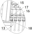
FIG. 5 is a schematic structural diagram of a detection assembly in an embodiment of an online monitoring device for the thickness of a metal plate coating of a fuel cell.
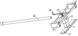
Fig. 6 is a schematic diagram of a transmission structure in an embodiment of an online monitoring device for the thickness of a metal plate coating of a fuel cell.
FIG. 7 is a schematic diagram of another angle of the transmission structure in the embodiment of the device for on-line monitoring the coating thickness of the metal plate of the fuel cell.
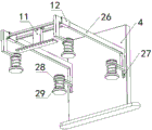
Fig. 8 is a schematic structural diagram of a pressing mechanism in an embodiment of an on-line monitoring device for the thickness of a metal plate coating of a fuel cell.
FIG. 9 is a wiring diagram of the inside of the detecting device in the embodiment of the fuel cell metal plate coating thickness on-line monitoring device.
In the figure: 1. a coating apparatus; 2. a linear conveying module; 3. a bearing plate; 4. a mounting frame; 5. a drive device; 6. a screw rod; 7. a chute; 8. a threaded sleeve; 9. a slider; 10. moving the sleeve plate; 11. lifting sleeve plates; 12. a sliding sleeve; 13. a measurement probe; 14. a connecting frame; 15. a detection device; 16. a first spring; 17. an upper limiting ring; 18. a lower limit ring; 19. a gear; 20. a rack plate; 21. a guide sleeve; 22. a guide rod; 23. a grooved wheel; 24. pulling the cable; 25. a follower; 26. a lifting frame; 27. a guide groove; 28. a butting rod; 29. a second spring; 30. a movable end; 31. a transverse plate.
Detailed Description
The technical solutions in the embodiments of the present invention will be clearly and completely described below with reference to the drawings in the embodiments of the present invention, and it is obvious that the described embodiments are only a part of the embodiments of the present invention, and not all of the embodiments. All other embodiments, which can be derived by a person skilled in the art from the embodiments given herein without making any creative effort, shall fall within the protection scope of the present invention.
In addition, an element of the present invention may be said to be "fixed" or "disposed" to another element, either directly on the other element or with intervening elements present. When an element is referred to as being "connected" to another element, it can be directly connected to the other element or intervening elements may also be present. The terms "vertical," "horizontal," "left," "right," and the like as used herein are for illustrative purposes only and do not represent the only embodiments.
Referring to fig. 1 to 9, in an embodiment of the present invention, an online monitoring apparatus for a thickness of a metal plate coating of a fuel cell includes: coating equipment 1, detection subassembly, power unit and mechanism pushes down.
The coating device 1 is movably provided with a bearing plate 3 for bearing the fuel cell, specifically, the bearing plate 3 is connected with the linear conveying module 2 on the coating device 1, so that the bearing plate 3 can move on the linear conveying module 2;
the coating device 1 is also detachably provided with a mounting frame 4, the lower part of the mounting frame 4 is provided with a detection assembly, the detection assembly comprises a transverse plate 31 fixedly mounted at one end of the lifting assembly, which is far away from the mounting frame 4, the transverse plate 31 is equidistantly provided with a plurality of through holes, a measuring probe 13 is slidably mounted in each through hole, the upper end part of each measuring probe 13 is connected with a detection device 15, and the detection device 15 is connected with the lifting assembly through a connecting frame 14;
The detection device 15 is internally provided with a power supply, a work indicator light, an ammeter, a slide rheostat and a switch, the five are sequentially connected through a lead, and the upper end part of the measurement probe 13 is connected with the movable end 30 on the slide rheostat, so that the resistance value of the slide rheostat can be adjusted when the measurement probe 13 detects, the numerical value of the ammeter is further changed, and an alarm is given when the numerical value of the current becomes higher than or lower than a preset value.
When the device is used, a metal pole plate of the fuel cell is subjected to film generation by the coating device 1, then the metal pole plate is conveyed to the position right below the mounting frame 4 by the linear conveying module 2 and is kept static, then the plurality of measuring probes 13 move towards the metal pole plate of the fuel cell and continue to move for a certain displacement after contacting with the metal pole plate of the fuel cell, so that the first spring 16 is further compressed on the basis of the initial compression amount, and at the moment, the resistance value of the slide rheostat in the detection device 15 generates an initial value which is taken as an intermediate value, and a preset value of an ammeter is set.
For example: the power supply voltage is 5mV, the total internal resistance of the ammeter and the internal resistance of the working indicator lamp is 1m omega, the maximum resistance value of the slide rheostat is 4m omega, when the measuring probe 13 is not in contact with the metal pole plate of the fuel cell, the slide rheostat is short-circuited, the resistance value in the detection device 15 is the minimum, namely 1m omega, the number of the ammeter is 5mA at the moment, when the measuring probe 13 is in contact with the metal pole plate of the fuel cell and drives the measuring probe 13 to move upwards, the movable end 30 of the slide rheostat moves upwards at the moment to increase the resistance value of the slide rheostat in a line in series connection, and if the resistance value of the slide rheostat in the line in series connection at the moment is 1m omega, the total resistance value in the line is 2m omega at the moment, the number of the ammeter is 2.5mA, the preset number of the ammeter can be set to be 2 to 3mA according to the production standard.
When the preset value of the ammeter is adjusted, the measuring probes 13 are driven to move along the length direction of the metal pole plate of the fuel cell, when the thickness of the thin film on the metal pole plate of the fuel cell does not accord with the production standard, the thickness of the thin film is larger than the standard range value or smaller than the standard value, the measuring probes 13 correspondingly move upwards or downwards firstly, the resistance value of the slide rheostat connected in the line is increased or reduced, the numerical value of the ammeter is increased or reduced along with the increase, and when the numerical value of the ammeter is larger than 3mA or smaller than 2mA, an alarm is given.
The measuring probes 13 are equidistantly arranged in the direction perpendicular to the movement direction of the measuring probes, so that a plurality of areas on the surface of the metal polar plate of the fuel cell can be detected during detection, and compared with the traditional method of judging the thickness of the film by adopting a plasma concentration detection result, the method has the advantage that the detection result is more accurate.
Referring to fig. 1, 5, 6, and 7, the measuring probe 13 is connected to a power mechanism on the mounting frame 4, the power mechanism can drive the detecting assembly to move along the length direction of the metal plate of the fuel cell, the power mechanism includes a power assembly and a lifting assembly, and the lifting assembly can drive the detecting assembly to move toward the metal plate of the fuel cell when the detecting assembly moves;
the power assembly comprises a driving device 5 fixedly mounted on the mounting frame 4, an output shaft of the driving device 5 is connected with a screw rod 6 rotatably mounted on the mounting frame 4, a threaded sleeve 8 in threaded connection with the screw rod 6 is arranged on the screw rod 6, and the threaded sleeve 8 is fixedly connected with a sliding block 9 in a sliding groove 7 sliding on the mounting frame 4;
the lifting assembly comprises a movable sleeve plate 10 connected to the sliding block 9, a lifting sleeve plate 11 is slidably mounted in the movable sleeve plate 10, one end, far away from the sliding block 9, of the lifting sleeve plate 11 is fixedly connected with the transverse plate 31, and the lifting sleeve plate 11 is connected with the movable sleeve plate 10 through a transmission structure;
the transmission structure comprises a rotating shaft which penetrates through the movable sleeve plate 10 and is rotatably arranged, one end of the rotating shaft is coaxially connected with a gear 19, and the gear 19 is matched with a rack plate 20 arranged on the mounting rack 4;
the transmission structure further comprises two grooved wheels 23 rotatably mounted on the side wall of the movable sleeve plate 10, a traction cable 24 is sleeved between the two grooved wheels 23, the traction cable 24 is connected with the lifting sleeve plate 11 through a follower 25, and one of the grooved wheels 23 is coaxially connected with the other end of the rotating shaft;
be provided with between gear 19 with mounting bracket 4 and be used for to gear 19 carries out spacing locking structure, locking structure include with gear 19's pivot fixed connection's guide sleeve 21, guide sleeve 21 with install guide bar 22 adaptation on mounting bracket 4.
When the measuring probe 13 is used, when a metal pole plate of a fuel cell moves to the position right below the mounting frame 4, the driving device 5 is controlled to work, at the moment, an output shaft of the driving device 5 drives the screw rod 6 connected with the driving device to rotate, the threaded sleeve 8 which is arranged on the screw rod 6 and in threaded connection with the screw rod 6 moves in the axial direction of the screw rod 6, and then the measuring probe 13 is driven to move, wherein the threaded sleeve 8 is connected with the sliding block 9, the sliding block 9 slides in the sliding groove 7, the phenomenon that the threaded sleeve 8 rotates along with the screw rod 6 is effectively avoided, the threaded sleeve 8 moves more stably when the screw rod 6 rotates, meanwhile, the screw rod 6 is in threaded connection with the threaded sleeve 8, the threaded connection has high precision, slight difference exists in the length of the metal pole plate of the fuel cell, here, the lead rod 6 and the threaded sleeve 8 can be used for realizing the precise control over-control over the measuring probe 13, and the measuring probe 13 is prevented from moving excessively and interfering with other components on the fuel cell to cause damage to the measuring probe 13.
When the sliding block 9 moves along with the threaded sleeve 8, the movable sleeve plate 10 fixedly connected with the sliding block 9 is driven to move, and the lifting sleeve plate 11 sleeved in the movable sleeve plate 10 is driven to move, in an initial state, the gear 19 on the movable sleeve plate 10 is in a meshed state with the rack plate 20, so that when the movable sleeve plate 10 moves, the gear 19 rotates under the action of the rack plate 20 and drives one of the grooved wheels 23 to rotate through the rotating shaft, the traction cable 24 is sleeved between the two grooved wheels 23 and is connected with the lifting sleeve plate 11 through the follower 25, when one of the grooved wheels 23 rotates, the traction cable 24 acts and drives the lifting sleeve plate 11 to move downwards relative to the movable sleeve plate 10, after the measuring probe 13 abuts against a metal pole plate of a fuel cell, the lifting sleeve plate 11 is continuously driven to move downwards for a certain stroke amount, the gear 19 is separated from the rack plate 20, and through the arrangement, when the metal pole plate of the fuel cell moves, the measuring probe 13 is separated from the pole plate to prevent the metal pole plate of the fuel cell from interfering with the metal pole plate of the measuring probe 13 when the metal moves, and the measuring probe 13 is damaged, so that the structure of the measuring probe 13 is damaged.
And in the initial state, the central axis of the guide sleeve 21 on the gear 19 is collinear with the central axis of the guide rod 22, the guide sleeve 21 will follow the rotation of the gear 19, and at the moment when the gear 19 is separated from the rack plate 20, the central axis of the guide sleeve 21 is collinear with the central axis of the guide rod 22 again, and at the moment when the gear 19 is separated from the rack plate 20, the guide sleeve 21 just matches with the guide rod 22 in a sliding manner, i.e. the guide sleeve 21 slides on the guide rod 22, so that the gear 19 handles a locked state, in which state the traction cable 24 is kept stationary, and the lifting sleeve plate 11 is kept stationary relative to the moving sleeve plate 10, and at the moment, the distance between the lower end part of the lifting sleeve plate 11 and the metal pole plate of the fuel cell is constant, so that when the height of the measuring probe 13 changes during the process that the lifting sleeve plate 11 follows the slider 9, only the film thickness on the surface of the metal pole plate of the fuel cell may change, that the influence of other factors on the detection result is reduced, and the accuracy of the result is improved.
Referring to fig. 8, a pressing mechanism is further installed on the mounting frame 4, and the pressing mechanism abuts against the metal pole plate of the fuel cell before the detection assembly is attached to the metal pole plate of the fuel cell;
the downward pressing mechanism comprises two sliding sleeves 12 connected with the lifting sleeve plate 11, the sliding sleeves 12 are connected with a lifting frame 26 arranged in the mounting rack 4 in a sliding manner, and the lifting frame 26 slides in a guide groove 27 on the inner wall of the mounting rack 4;
the both ends of crane 26 still are provided with elasticity butt structure, elasticity butt structure is including sliding the setting the butt pole 28 at crane 26 both ends, the both ends of butt joint pole 28 all are provided with the boss, just the cover is equipped with No. two spring 29 on the butt joint pole 28, no. two spring 29's one end with crane 26 is connected, the other end with under the butt joint pole 28 tip the boss is connected.
In the initial state, the height of the lower end of the abutting rod 28 is lower than that of the lower end of the measuring probe 13, before the lifting sleeve plate 11 moves downwards to drive the measuring probe 13 to contact with a metal pole plate of the fuel cell, the lower end of the abutting rod 28 is already abutted against the fuel cell and compresses the second spring 29, the fuel cell is fixed by the elastic force of the second spring 29, and the situation that the fuel cell displaces when the measuring probe 13 detects is avoided, and therefore detection accuracy is affected.
In summary, when the fuel cell is used, when a metal pole plate of the fuel cell moves to a position right below the mounting frame 4, the driving device 5 is controlled to operate, at this time, an output shaft of the driving device 5 drives the screw rod 6 connected with the screw rod to rotate, and the threaded sleeve 8 which is arranged on the screw rod 6 and is in threaded connection with the screw rod 6 moves in the axial direction of the screw rod 6, so as to drive the measuring probe 13 to move, wherein the threaded sleeve 8 is connected with the sliding block 9, and the sliding block 9 slides in the sliding groove 7, so that the phenomenon that the threaded sleeve 8 rotates along with the screw rod 6 is effectively avoided, and when the screw rod 6 rotates, the threaded sleeve 8 moves more stably, meanwhile, the screw rod 6 and the threaded sleeve 8 are in threaded connection, and the threaded connection has very high precision, and the length of the metal pole plate of the fuel cell has slight difference, here, the precision control over the detecting probe 13 can be realized through the screw rod 6 and the threaded sleeve 8, and the measuring probe 13 is prevented from excessively moving and interfering with other components on the fuel cell to cause damage to the measuring probe 13.
When the sliding block 9 moves along with the threaded sleeve 8, the movable sleeve plate 10 fixedly connected with the sliding block 9 is driven to move, and the lifting sleeve plate 11 sleeved in the movable sleeve plate 10 is driven to move, in an initial state, the gear 19 on the movable sleeve plate 10 is in a meshing state with the rack plate 20, so that when the movable sleeve plate 10 moves, the gear 19 rotates under the action of the rack plate 20 and drives one of the sheaves 23 to rotate through the rotating shaft, the traction cable 24 is sleeved between the two sheaves 23, the traction cable 24 is connected with the lifting sleeve plate 11 through the follower 25, so that when one of the sheaves 23 rotates, the traction cable 24 acts and drives the lifting sleeve plate 11 to move downwards relative to the movable sleeve plate 10, after the measuring probe 13 abuts against a metal plate of the fuel cell, the lifting sleeve plate 11 is continuously driven to move downwards for a certain stroke, the gear 19 is separated from the rack plate 20, and through the arrangement, when the metal plate of the fuel cell moves, the measuring probe 13 is separated from the metal plate to prevent the metal plate of the fuel cell from interfering with the metal plate 13 when the metal plate of the fuel cell moves, and the structure of the measuring probe 13 is damaged.
And in the initial state, the central axis of the guide sleeve 21 on the gear 19 is collinear with the central axis of the guide rod 22, the guide sleeve 21 will follow the rotation of the gear 19, and at the moment when the gear 19 is separated from the rack plate 20, the central axis of the guide sleeve 21 is collinear with the central axis of the guide rod 22 again, and at the moment when the gear 19 is separated from the rack plate 20, the guide sleeve 21 just matches with the guide rod 22 in a sliding manner, i.e. the guide sleeve 21 slides on the guide rod 22, so that the gear 19 handles a locked state, in which state the traction cable 24 is kept stationary, and the lifting sleeve plate 11 is kept stationary relative to the moving sleeve plate 10, and at the moment, the distance between the lower end part of the lifting sleeve plate 11 and the metal pole plate of the fuel cell is constant, so that when the height of the measuring probe 13 changes during the process that the lifting sleeve plate 11 follows the slider 9, only the film thickness on the surface of the metal pole plate of the fuel cell may change, that the influence of other factors on the detection result is reduced, and the accuracy of the result is improved.
When the device is used, a metal pole plate of the fuel cell is subjected to film generation by the coating device 1, then the metal pole plate is conveyed to the position right below the mounting frame 4 by the linear conveying module 2 and is kept static, then the plurality of measuring probes 13 move towards the metal pole plate of the fuel cell and continue to move for a certain displacement after contacting with the metal pole plate of the fuel cell, so that the first spring 16 is further compressed on the basis of the initial compression amount, and at the moment, the resistance value of the slide rheostat in the detection device 15 generates an initial value, and the initial value is taken as an intermediate value to set a preset value of an ammeter.
For example: the power supply voltage is 5mV, the total internal resistance of the ammeter and the internal resistance of the working indicator lamp is 1m omega, the maximum resistance value of the slide rheostat is 4m omega, when the measuring probe 13 is not in contact with the metal pole plate of the fuel cell, the slide rheostat is short-circuited, the resistance value in the detection device 15 is the minimum, namely 1m omega, the number of the ammeter is 5mA at the moment, when the measuring probe 13 is in contact with the metal pole plate of the fuel cell and drives the measuring probe 13 to move upwards, the movable end 30 of the slide rheostat moves upwards at the moment to increase the resistance value of the slide rheostat in a line in series connection, and if the resistance value of the slide rheostat in the line in series connection at the moment is 1m omega, the total resistance value in the line is 2m omega at the moment, the number of the ammeter is 2.5mA, the preset number of the ammeter can be set to be 2 to 3mA according to the production standard.
When the preset value of the ammeter is adjusted, the measuring probes 13 are driven to move along the length direction of the metal pole plate of the fuel cell, when the thickness of the thin film on the metal pole plate of the fuel cell does not accord with the production standard, the thickness of the thin film is larger than the standard range value or smaller than the standard value, the measuring probes 13 correspondingly move upwards or downwards firstly, the resistance value of the slide rheostat connected in the circuit is increased or reduced, the value of the ammeter is increased or reduced along with the increase, and when the value of the ammeter is larger than 3A or smaller than 2A, an alarm is given.
The measuring probes 13 are equidistantly arranged in the direction perpendicular to the movement direction of the measuring probes, so that a plurality of areas on the surface of the metal polar plate of the fuel cell can be detected during detection, and compared with the traditional method of judging the thickness of the film by adopting a plasma concentration detection result, the method has the advantage that the detection result is more accurate.
In the initial state, the height of the lower end of the abutting rod 28 is lower than that of the lower end of the measuring probe 13, before the lifting sleeve plate 11 moves downwards to drive the measuring probe 13 to contact with a metal pole plate of the fuel cell, the lower end of the abutting rod 28 is already abutted against the fuel cell and compresses the second spring 29, the fuel cell is fixed by the elastic force of the second spring 29, and the situation that the fuel cell displaces when the measuring probe 13 detects is avoided, and therefore detection accuracy is affected.
It will be evident to those skilled in the art that the invention is not limited to the details of the foregoing illustrative embodiments, and that the present invention may be embodied in other specific forms without departing from the spirit or essential attributes thereof. The present embodiments are therefore to be considered in all respects as illustrative and not restrictive, the scope of the invention being indicated by the appended claims rather than by the foregoing description, and all changes which come within the meaning and range of equivalency of the claims are therefore intended to be embraced therein. Any reference sign in a claim should not be construed as limiting the claim concerned.
Furthermore, it should be understood that although the present description refers to embodiments, not every embodiment may contain only a single embodiment, and such description is for clarity only, and those skilled in the art should integrate the description, and the embodiments may be combined as appropriate to form other embodiments understood by those skilled in the art.
Claims (6)
1. Fuel cell metal polar plate coating thickness on-line monitoring device, its characterized in that includes:
the coating device (1) is movably provided with a bearing plate (3) used for bearing the fuel cell;
the coating equipment (1) is also detachably provided with an installation frame (4), a detection assembly is arranged at the lower part of the installation frame (4), the detection assembly is connected with a power mechanism on the installation frame (4), the power mechanism can drive the detection assembly to move along the length direction of the metal polar plate of the fuel cell, the power mechanism comprises a power assembly and a lifting assembly, and the lifting assembly can drive the detection assembly to move towards the metal polar plate of the fuel cell when the detection assembly moves;
the mounting rack (4) is also provided with a pressing mechanism, and the pressing mechanism is abutted to the metal polar plate of the fuel cell before the detection assembly is attached to the metal polar plate of the fuel cell;
the detection assembly comprises a transverse plate (31) fixedly mounted at one end, far away from the mounting frame (4), of the lifting assembly, a plurality of through holes are formed in the transverse plate (31) at equal intervals, a measuring probe (13) is slidably mounted in each through hole, the upper end of each measuring probe (13) is connected with a detection device (15), and the detection device (15) is connected with the lifting assembly through a connecting frame (14);
an upper limiting ring (17) and a lower limiting ring (18) are arranged on the measuring probe (13), a first spring (16) is sleeved on the measuring probe (13), one end of the first spring (16) is connected with the lower limiting ring (18), and the other end of the first spring is connected with the transverse plate (31);
the power assembly comprises a driving device (5) fixedly mounted on the mounting rack (4), an output shaft of the driving device (5) is connected with a screw rod (6) rotatably mounted on the mounting rack (4), a threaded sleeve (8) in threaded connection with the screw rod (6) is arranged on the screw rod (6), and the threaded sleeve (8) is fixedly connected with a sliding block (9) sliding in a sliding groove (7) on the mounting rack (4);
the upper end of the measuring probe (13) is connected with a movable end (30) on the slide rheostat.
2. The device for monitoring the thickness of the metal electrode plate coating of the fuel cell in the online manner is characterized in that the lifting assembly comprises a movable sleeve plate (10) connected to the sliding block (9), a lifting sleeve plate (11) is slidably mounted in the movable sleeve plate (10), one end, far away from the sliding block (9), of the lifting sleeve plate (11) is fixedly connected with the transverse plate (31), and the lifting sleeve plate (11) is connected with the movable sleeve plate (10) through a transmission structure.
3. The fuel cell metal polar plate coating thickness on-line monitoring device according to claim 2, characterized in that the transmission structure comprises a rotating shaft which is rotatably arranged through the movable sleeve plate (10), one end of the rotating shaft is coaxially connected with a gear (19), and the gear (19) is matched with a rack plate (20) arranged on the mounting frame (4);
the transmission structure further comprises two grooved wheels (23) rotatably mounted on the side wall of the movable sleeve plate (10), a traction cable (24) is sleeved between the two grooved wheels (23), and the traction cable (24) is connected with the lifting sleeve plate (11) through a follower (25);
one sheave (23) is coaxially connected with the other end of the rotating shaft.
4. The fuel cell metal plate coating thickness on-line monitoring device according to claim 3, characterized in that a locking structure for limiting the gear (19) is arranged between the gear (19) and the mounting rack (4);
the locking structure comprises a guide sleeve (21) fixedly connected with a rotating shaft of the gear (19), and the guide sleeve (21) is matched with a guide rod (22) installed on the installation rack (4).
5. The fuel cell metal polar plate coating thickness on-line monitoring device of claim 2, characterized in that the pressing mechanism comprises two sliding sleeves (12) connected with the lifting sleeve plate (11), the sliding sleeves (12) are connected with a lifting frame (26) arranged in the mounting frame (4) in a sliding way, and the lifting frame (26) slides in a guide groove (27) on the inner wall of the mounting frame (4);
and elastic abutting structures are arranged at two ends of the lifting frame (26).
6. The fuel cell metal polar plate coating thickness on-line monitoring device of claim 5, characterized in that the elastic abutting structure comprises abutting rods (28) which are arranged at two ends of the lifting frame (26) in a sliding manner, bosses are arranged at two ends of the abutting rods (28), a second spring (29) is sleeved on the abutting rods (28), one end of the second spring (29) is connected with the lifting frame (26), and the other end of the second spring is connected with the bosses at the lower end of the abutting rods (28).
Priority Applications (1)
| Application Number | Priority Date | Filing Date | Title |
|---|---|---|---|
| CN202211453834.9A CN115491663B (en) | 2022-11-21 | 2022-11-21 | Fuel cell metal polar plate coating thickness on-line monitoring device |
Applications Claiming Priority (1)
| Application Number | Priority Date | Filing Date | Title |
|---|---|---|---|
| CN202211453834.9A CN115491663B (en) | 2022-11-21 | 2022-11-21 | Fuel cell metal polar plate coating thickness on-line monitoring device |
Publications (2)
| Publication Number | Publication Date |
|---|---|
| CN115491663A CN115491663A (en) | 2022-12-20 |
| CN115491663B true CN115491663B (en) | 2023-03-24 |
Family
ID=85114728
Family Applications (1)
| Application Number | Title | Priority Date | Filing Date |
|---|---|---|---|
| CN202211453834.9A Active CN115491663B (en) | 2022-11-21 | 2022-11-21 | Fuel cell metal polar plate coating thickness on-line monitoring device |
Country Status (1)
| Country | Link |
|---|---|
| CN (1) | CN115491663B (en) |
Citations (2)
| Publication number | Priority date | Publication date | Assignee | Title |
|---|---|---|---|---|
| SU1260419A1 (en) * | 1985-05-15 | 1986-09-30 | Предприятие П/Я М-5288 | System for automatic monitoring of mean thickness of electrodeposited coating |
| CN205799248U (en) * | 2016-07-21 | 2016-12-14 | 湖南科技大学 | A kind of ELID grinding oxide thickness dynamic Detection & Controling device |
Family Cites Families (13)
| Publication number | Priority date | Publication date | Assignee | Title |
|---|---|---|---|---|
| GB1083231A (en) * | 1963-12-12 | 1967-09-13 | Egyesuelt Izzolampa | Electronic equipment for controlling the formation or gauging the thickness of metallic films |
| US3397672A (en) * | 1965-11-10 | 1968-08-20 | United States Steel Corp | Control system for vapor-deposition coating apparatus |
| US3620814A (en) * | 1968-08-09 | 1971-11-16 | Bell Telephone Labor Inc | Continuous measurement of the thickness of hot thin films |
| AU614904B2 (en) * | 1989-07-31 | 1991-09-12 | American Telephone And Telegraph Company | Measuring and controlling the thickness of a coating on a elongated article |
| JPH05133734A (en) * | 1991-03-06 | 1993-05-28 | Anritsu Corp | Thickness sensor |
| JPH10163182A (en) * | 1996-11-29 | 1998-06-19 | Dainippon Screen Mfg Co Ltd | Substrate heat treatment equipment and film thickness measuring equipment which can be used in substrate heat treatment equipment |
| JP4811108B2 (en) * | 2006-05-10 | 2011-11-09 | 住友電気工業株式会社 | Coating layer thickness measuring mechanism and coating layer forming apparatus using the same |
| CN204228101U (en) * | 2014-12-04 | 2015-03-25 | 中交第一公路勘察设计研究院有限公司 | Two parallel probe formula rain water depth on road surface tester |
| CN206656687U (en) * | 2017-04-28 | 2017-11-21 | 河南新友工程机械有限公司 | A kind of multi-purpose coating thickness detector |
| CN208109003U (en) * | 2018-05-18 | 2018-11-16 | 肖楠 | A kind of thickness measurement device of plate |
| CN109557375B (en) * | 2019-01-23 | 2024-11-08 | 常州翊迈新材料科技有限公司 | A continuous automatic detection device for contact resistance of fuel cell bipolar plates |
| CN210570515U (en) * | 2019-11-29 | 2020-05-19 | 咸阳师范学院 | Equipment for Measuring Film Thickness and Uniformity of Vacuum Ion Plating and Plasma Spray Coatings |
| CN217112507U (en) * | 2022-01-26 | 2022-08-02 | 常州翊迈新材料科技有限公司 | Contact resistance test system |
-
2022
- 2022-11-21 CN CN202211453834.9A patent/CN115491663B/en active Active
Patent Citations (2)
| Publication number | Priority date | Publication date | Assignee | Title |
|---|---|---|---|---|
| SU1260419A1 (en) * | 1985-05-15 | 1986-09-30 | Предприятие П/Я М-5288 | System for automatic monitoring of mean thickness of electrodeposited coating |
| CN205799248U (en) * | 2016-07-21 | 2016-12-14 | 湖南科技大学 | A kind of ELID grinding oxide thickness dynamic Detection & Controling device |
Also Published As
| Publication number | Publication date |
|---|---|
| CN115491663A (en) | 2022-12-20 |
Similar Documents
| Publication | Publication Date | Title |
|---|---|---|
| CN107064637B (en) | Electrical sheet surface insulation resistance measuring device | |
| CN115876139B (en) | Thickness detection device of panel | |
| CN115491663B (en) | Fuel cell metal polar plate coating thickness on-line monitoring device | |
| CN103278130A (en) | Clutch friction plate flatness testing equipment and using method thereof | |
| CN115265452A (en) | Automatic online detection device for wire diameter of electronic wire | |
| CN108592777A (en) | Moveable metallized film sheet resistance in-service monitoring device | |
| CN213145805U (en) | Tension detector for detecting tension of product | |
| CN108844439A (en) | A kind of continous way flat cold-rolled sheet thickness precise measurement instrument | |
| CN111398056A (en) | Superfine coaxial cable | |
| CN219758481U (en) | Magnetic field intensity measuring equipment for magnetron sputtering cathode magnetic rod | |
| CN110146001B (en) | Coupler concentricity correcting device | |
| CN219319329U (en) | Laser calliper | |
| CN109244560B (en) | Tension buffer memory mechanism | |
| CN211907100U (en) | Lacquering device capable of automatically controlling lacquering film of enameled wire | |
| JPH07294239A (en) | Automatic measuring apparatus for circular object | |
| CN114501863A (en) | Device and method for knife coating alignment calibration | |
| CN219871102U (en) | Automatic detection system for coating electrode | |
| CN108296659B (en) | Electric smelting vibration material disk equipment | |
| CN223449151U (en) | A spindle maintenance and testing platform | |
| CN220097466U (en) | Automatic adjusting device for conveyor belt | |
| CN113588475A (en) | Intelligent paint film scratch tester and test method | |
| CN222013371U (en) | An evaporation boat clamping inspection system for conductive metal film production | |
| CN214278373U (en) | Battery Swell Test Equipment | |
| CN224212820U (en) | A diamond busbar whitening machine with wire diameter detection | |
| CN224175787U (en) | Cable production length detects frock |
Legal Events
| Date | Code | Title | Description |
|---|---|---|---|
| PB01 | Publication | ||
| PB01 | Publication | ||
| SE01 | Entry into force of request for substantive examination | ||
| SE01 | Entry into force of request for substantive examination | ||
| GR01 | Patent grant | ||
| GR01 | Patent grant |