CN115464232B - Battery piece welding mechanism - Google Patents
Battery piece welding mechanism Download PDFInfo
- Publication number
- CN115464232B CN115464232B CN202211359014.3A CN202211359014A CN115464232B CN 115464232 B CN115464232 B CN 115464232B CN 202211359014 A CN202211359014 A CN 202211359014A CN 115464232 B CN115464232 B CN 115464232B
- Authority
- CN
- China
- Prior art keywords
- fixed
- welding
- plate
- battery piece
- welding mechanism
- Prior art date
- Legal status (The legal status is an assumption and is not a legal conclusion. Google has not performed a legal analysis and makes no representation as to the accuracy of the status listed.)
- Active
Links
Images


Classifications
-
- B—PERFORMING OPERATIONS; TRANSPORTING
- B23—MACHINE TOOLS; METAL-WORKING NOT OTHERWISE PROVIDED FOR
- B23K—SOLDERING OR UNSOLDERING; WELDING; CLADDING OR PLATING BY SOLDERING OR WELDING; CUTTING BY APPLYING HEAT LOCALLY, e.g. FLAME CUTTING; WORKING BY LASER BEAM
- B23K3/00—Tools, devices, or special appurtenances for soldering, e.g. brazing, or unsoldering, not specially adapted for particular methods
- B23K3/02—Soldering irons; Bits
- B23K3/03—Soldering irons; Bits electrically heated
-
- B—PERFORMING OPERATIONS; TRANSPORTING
- B23—MACHINE TOOLS; METAL-WORKING NOT OTHERWISE PROVIDED FOR
- B23K—SOLDERING OR UNSOLDERING; WELDING; CLADDING OR PLATING BY SOLDERING OR WELDING; CUTTING BY APPLYING HEAT LOCALLY, e.g. FLAME CUTTING; WORKING BY LASER BEAM
- B23K3/00—Tools, devices, or special appurtenances for soldering, e.g. brazing, or unsoldering, not specially adapted for particular methods
- B23K3/08—Auxiliary devices therefor
- B23K3/087—Soldering or brazing jigs, fixtures or clamping means
-
- B—PERFORMING OPERATIONS; TRANSPORTING
- B23—MACHINE TOOLS; METAL-WORKING NOT OTHERWISE PROVIDED FOR
- B23K—SOLDERING OR UNSOLDERING; WELDING; CLADDING OR PLATING BY SOLDERING OR WELDING; CUTTING BY APPLYING HEAT LOCALLY, e.g. FLAME CUTTING; WORKING BY LASER BEAM
- B23K2101/00—Articles made by soldering, welding or cutting
- B23K2101/36—Electric or electronic devices
-
- Y—GENERAL TAGGING OF NEW TECHNOLOGICAL DEVELOPMENTS; GENERAL TAGGING OF CROSS-SECTIONAL TECHNOLOGIES SPANNING OVER SEVERAL SECTIONS OF THE IPC; TECHNICAL SUBJECTS COVERED BY FORMER USPC CROSS-REFERENCE ART COLLECTIONS [XRACs] AND DIGESTS
- Y02—TECHNOLOGIES OR APPLICATIONS FOR MITIGATION OR ADAPTATION AGAINST CLIMATE CHANGE
- Y02E—REDUCTION OF GREENHOUSE GAS [GHG] EMISSIONS, RELATED TO ENERGY GENERATION, TRANSMISSION OR DISTRIBUTION
- Y02E10/00—Energy generation through renewable energy sources
- Y02E10/50—Photovoltaic [PV] energy
-
- Y—GENERAL TAGGING OF NEW TECHNOLOGICAL DEVELOPMENTS; GENERAL TAGGING OF CROSS-SECTIONAL TECHNOLOGIES SPANNING OVER SEVERAL SECTIONS OF THE IPC; TECHNICAL SUBJECTS COVERED BY FORMER USPC CROSS-REFERENCE ART COLLECTIONS [XRACs] AND DIGESTS
- Y02—TECHNOLOGIES OR APPLICATIONS FOR MITIGATION OR ADAPTATION AGAINST CLIMATE CHANGE
- Y02P—CLIMATE CHANGE MITIGATION TECHNOLOGIES IN THE PRODUCTION OR PROCESSING OF GOODS
- Y02P70/00—Climate change mitigation technologies in the production process for final industrial or consumer products
- Y02P70/50—Manufacturing or production processes characterised by the final manufactured product
Abstract
The invention discloses a battery piece welding mechanism, which relates to the technical field of battery piece welding and solves the problems of inclined welding belt and overflow of welding beads during the welding of the conventional battery piece.
Description
Technical Field
The invention relates to the technical field of battery piece welding, in particular to a battery piece welding mechanism.
Background
The solar cell panel is formed by splicing a plurality of battery pieces, the electrodes of two adjacent battery pieces are connected, and the two adjacent battery pieces are required to be welded through a welding strip.
When a battery piece is welded, firstly, a welding strip with a proper length needs to be selected, then the welding strip is aligned to the position of a main grid on a solar panel, then the welding strip is pushed and welded from right to left by an electric iron to complete a single welding operation, then the welding strip which is extended out is welded in a grid line on the back surface of another battery piece to complete series welding, in the manual welding process, a tin layer on the welding strip is melted by the electric iron and is connected with the main grid to realize welding, but when the welding strip is placed in the main grid, the welding strip is not tightly attached to the inside of a main grid groove or even is separated from the main grid, at the moment, the welding strip is very easy to butt joint with the inside of the main grid groove after the tin layer is melted, welding beads and welding slag are remained on the outer side of the main grid groove of the battery piece, chinese patent document CN103785916B discloses a welding tool for welding the welding strip on the solar panel, the welding strip can be brought into strip-shaped high-temperature cloth by a designed structure, the problem that the welding strip can be well accumulated on the welding strip-shaped high-temperature cloth can be solved, but the welding mechanism can be accumulated in a better way, the welding mechanism can only for the welding of the main grid, and the invention can be used for welding of the invention.
Disclosure of Invention
The invention aims to provide a cell welding mechanism capable of pressing a welding strip into a main grid groove and processing overflowing welding beads, so as to solve the problems in the background technology.
In order to achieve the purpose, the invention provides the following technical scheme that the battery piece welding mechanism comprises an electric soldering iron body and a clamping sleeve, wherein two supporting plates are rotatably butted outside the clamping sleeve through a rotating shaft, the clamping sleeve is sleeved with the outside of the electric soldering iron body, a connecting shaft is fixed at the bottom ends of the two supporting plates, and rollers are rotatably mounted at two ends of the connecting shaft through bearings;
the welding device comprises two butt-joint frames and a fixing frame, wherein two butt-joint frames and two fixing frames are fixed at two ends of a connecting shaft, a position correcting piece used for limiting a welding zone during welding of a battery piece is installed at the outer end of each butt-joint frame, the fixing frame is fixed on the outer side of the connecting shaft, and slag removing pieces used for cleaning residual welding beads outside main grid grooves of the battery piece are installed on two sides of each fixing frame.
Preferably, the deslagging piece comprises two prismatic rods fixed in the fixing frame, sleeve rods are inserted into the outer sides of the prismatic rods in a sliding mode, a connecting frame is fixed to the outer sides of the sleeve rods, high-temperature cloth is fixed to the bottom of the connecting frame, corrugated rings are fixed to the inner walls of the rollers, the outer ends of the sleeve rods are attached to the outer walls of the corrugated rings, the outer ends of the sleeve rods are of a hemispheroid structure, extrusion springs, which are abutted to the sleeve rods and the fixing frame, are sleeved on the outer sides of the prismatic rods, and move near the main grid grooves through the high-temperature cloth, so that overflowing welding beads can be wiped and removed.
Preferably, the link includes mounting panel and two L templates, two the L template is fixed with two loop bar outsides respectively, and two the L template is the inboard installing port that has all opened of L, the mounting panel top be fixed with two with the cardboard of installing port looks joint, and mounting panel bottom is fixed with high temperature cloth, through the mutual butt joint of cardboard and installing port for high temperature cloth is full to be dismantled.
Preferably, rectify the piece and include that two are rectified the position board, two rectify the position board and fix with two butt joint frame outer ends respectively, just the outer end of rectifying the position board is opened there is the chamfer, two rectify and be equipped with two-way threaded rod between the position board, and two rectify the position board and cup joint the both ends at two-way threaded rod respectively the screw thread, the outer end of two-way threaded rod is fixed with the regulation cap, rectifies the position board through coming two and mutually supports to make crooked welding strip can correct to the main grid inslot.
Preferably, the butt joint frame includes the connecting rod and fixes the curb plate of connecting axle outer end, connecting rod one end with the curb plate is fixed, and the other end with correct the position board fixed, through mutually supporting of curb plate and connecting rod for it is more laborsaving when two correct the position board and adjust.
Preferably, two it has the picture peg to peg graft between the position correcting board, just the picture peg bottom is fixed with the arc and supports the board, and the arc of design supports the board and can offsets with the welding area for weld laminating and main bars inslot that the area can be stable.
Preferably, the outer side of the roller is provided with a groove, the outer edge of the roller is fixed with anti-slip strips at equal angles, the weight of the roller is reduced due to the design of the groove, pushing is facilitated, and meanwhile the anti-slip strips are matched, so that when personnel push the electric soldering iron, the roller can be stably driven to roll.
Preferably, a connecting plate is fixed between the two supporting plates, an arc-shaped rod is inserted in the connecting plate in a sliding mode, a supporting strip which is abutted to the outer side of the clamping sleeve is fixed at the outer end of the arc-shaped rod, a limiting ball is fixed at the other end of the arc-shaped rod, an arc-shaped spring which is abutted to the supporting strip and the connecting plate is sleeved on the outer side of the arc-shaped rod, the designed arc-shaped spring can be pushed up under the condition that the electric iron is not subjected to external force, the bottom of the electric iron can be suspended, and the electric iron can be placed conveniently.
Preferably, the circle center of the arc-shaped rod is concentric with the rotating shaft at the top of the supporting plate, so that the electric soldering iron can rotate on the supporting plate along with the clamping sleeve, and when a person operates the electric soldering iron, the person can press the electric soldering iron to generate resistance, so that force can be applied when the electric soldering iron is operated, and the electric soldering iron can be pushed more stably.
Preferably, the battery piece welding mechanism further comprises an L-shaped abutting plate fixed on the welding table, the bottom of the horizontal plane of the L-shaped abutting plate is in contact with the connecting rod, the outer horizontal end of the L-shaped abutting plate is of an outward-turning structure, and the designed L-shaped abutting plate can abut against the connecting rod, so that the electric soldering iron can be stably placed when not in use and has a function similar to that of an inserting frame of the electric soldering iron.
Compared with the prior art, the invention has the beneficial effects that:
the clamping sleeve is clamped with the outer side of the electric soldering iron and matched with the supporting plate and the roller to roll on the battery piece, welding of the electric soldering iron to a welding strip is met in the rolling process, the welding strip can be corrected by matching with the designed correcting piece to be attached to the inner wall of the main grid groove, welding slag welding beads and the like generated in the welding process can be removed through the designed slag removing piece, and the welding quality is improved.
Drawings
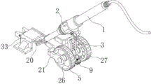
FIG. 1 is a schematic view of the overall structure of the present invention;
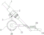
FIG. 2 is another perspective view of the present invention;
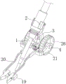
FIG. 3 is a side view in partial cross-section of the present invention;
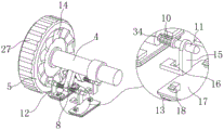
FIG. 4 is a partial cross-sectional structural schematic view of the present invention;
FIG. 5 is a schematic structural view of the electric soldering iron of the present invention with the body removed;
FIG. 6 is a schematic view of a partial cross-sectional structure of the electric soldering iron with the body removed according to the present invention;
FIG. 7 is a schematic view of a deslagging member of the present invention;
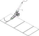
fig. 8 is a schematic diagram of the welding process of the invention for welding the welding strip on the battery piece.
In the figure: 1-electric iron body; 2-cutting the ferrule; 3-a support plate; 4-connecting the shaft; 5-a roller; 6-a docking cradle; 7-an orthotic; 8, fixing a frame; 9-deslagging parts; 10-prismatic rod; 11-a loop bar; 12-a connecting frame; 13-high temperature cloth; 14-a corrugated ring; 15-L-shaped plates; 16-a mounting port; 17-mounting a plate; 18-a card board; 19-a leveling plate; 20-a connecting rod; 21-side plate; 22-inserting plate; 23-arc resisting plate; 24-a two-way threaded rod; 25-an adjusting cap; 26-a groove; 27-antislip strips; 28-a connecting plate; 29-arc shaped rods; 30-a support strip; 31-a limit ball; 32-arc spring; a 33-L-shaped abutting plate; 34-pressing the spring.
Detailed Description
The technical solutions in the embodiments of the present invention will be clearly and completely described below with reference to the drawings in the embodiments of the present invention, and it is obvious that the described embodiments are only a part of the embodiments of the present invention, and not all of the embodiments. All other embodiments, which can be derived by a person skilled in the art from the embodiments given herein without making any creative effort, shall fall within the protection scope of the present invention.
Example 1
Referring to fig. 1-4 and 6, the battery piece welding mechanism shown in the figures comprises an electric soldering iron body 1 and a cutting ferrule 2, wherein two support plates 3 are rotatably butted on the outer side of the cutting ferrule 2 through a rotating shaft, the cutting ferrule 2 is sleeved with the outer side of the electric soldering iron body 1, a connecting shaft 4 is fixed at the bottom ends of the two support plates 3, and rollers 5 are rotatably mounted at the two ends of the connecting shaft 4 through bearings;
the two butt-joint frames 6 and the fixed frames 8 are fixed at two ends of the connecting shaft 4, the outer ends of the two butt-joint frames 6 are provided with leveling pieces 7 used for limiting welding belts during welding of the battery pieces, the fixed frames 8 are fixed on the outer side of the connecting shaft 4, and two sides of each fixed frame 8 are provided with slag removing pieces 9 used for cleaning residual welding beads on the outer side of a main grid groove of each battery piece;
it should be noted that: the designed roller 5 and the designed support plate 3 are in butt joint with electric soldering iron through the clamping sleeve 2, so that when a person welds a welding strip, the person only needs to plug one end of the welding strip into the main grid groove, then the electric soldering iron is aligned with the welding strip to be welded, and then the electric soldering iron is pushed to weld the welding strip in the main grid groove on the battery piece.
It is worth noting that: when the electric iron is pushed, the position correcting piece 7 arranged on the butt joint frame 6 can correct and correct the welding strip to be welded, so that the welding strip is positioned in the main grid groove, and meanwhile, the slag removing piece 9 is matched to remove the welding bead overflowing during welding.
It should also be noted that: the gyro wheel 5 and the backup pad 3 of design can support the electric iron for during the propelling movement, personnel's operation is more laborsaving, and wherein, cutting ferrule 2 adopts but not limited to the rubber material and makes, has the round hole with electric iron looks adaptation in, makes after the cutting ferrule, does not have external force to break off with the fingers and thumb under the condition and can not break away from with the electric iron, satisfies the butt joint and the dismantlement to electric iron body 1, makes the use of electric iron nimble more convenient.
Referring to fig. 2, 6 and 7, the slag removing element 9 in the figure includes two prismatic rods 10 fixed in the fixing frame 8, loop bars 11 are inserted in the outer sides of the two prismatic rods 10 in a sliding manner, a connecting frame 12 is fixed on the outer sides of the two loop bars 11, a high temperature cloth 13 is fixed at the bottom of the connecting frame 12, a corrugated ring 14 is fixed on the inner wall of the roller 5, the outer end of the loop bar 11 is attached to the outer wall of the corrugated ring 14, the outer end of the loop bar 11 is of a hemispheroid structure, and an extruding spring 34 which is abutted against the loop bar 11 and the fixing frame 8 is sleeved on the outer side of the prismatic rod 10;
it should be noted that: when the propelling movement, gyro wheel 5 can rotate to drive ripple ring 14 and rotate, under extrusion spring 34's effect, make loop bar 11 outside and ripple ring 14's outer wall laminate mutually, and along with ripple ring 14's rotation, make loop bar 11 reciprocating motion on prism pole 10, thereby make the high temperature cloth 13 of laminating mutually with the battery piece outer wall can be near main grid groove reciprocating motion, push into main grid inslot with the welding bead that spills over, perhaps directly wipe and dispose.
Referring to fig. 7, the connecting frame 12 shown in the figure comprises a mounting plate 17 and two L-shaped plates 15, the two L-shaped plates 15 are respectively fixed to the outer sides of the two loop bars 11, mounting openings 16 are formed in the two L-shaped plates 15, two clamping plates 18 clamped with the mounting openings 16 are fixed to the top of the mounting plate 17, and the bottom of the mounting plate 17 is fixed to the high-temperature cloth 13;
it should be noted that: the clamping plate 18 fixed on the mounting plate 17 is clamped with the mounting opening 16 formed in the L-shaped plate 15, so that the mounting plate 17 and the L-shaped plate 15 can be detachably mounted, the high-temperature cloth 13 can be conveniently detached and cleaned, and the requirement of quickly replacing the high-temperature cloth 13 in the continuous welding process is met;
it is worth noting that: the direction of the clamping plate 18 moving in the mounting opening 16 is perpendicular to the direction of the sleeve rod 11 moving, so that the sleeve rod 11 can move on the prismatic rod 10 in a reciprocating mode without loosening the mounting plate 17.
In addition, referring to fig. 1 and fig. 3 to fig. 5, the correcting member 7 in the drawings includes two correcting plates 19, the two correcting plates 19 are respectively fixed to the outer ends of the two docking frames 6, the outer ends of the correcting plates 19 are provided with chamfers, a bidirectional threaded rod 24 is arranged between the two correcting plates 19, the two correcting plates 19 are respectively sleeved at two ends of the bidirectional threaded rod 24 in a threaded manner, and the outer ends of the bidirectional threaded rod 24 are fixed with adjusting caps 25;
it should be noted that: the distance between the two position correcting plates 19 is slightly larger than the width of the main grid groove on the battery piece, when the electric soldering iron moves, the welding strip abuts against the inner walls of the two position correcting plates 19, so that the welding strip at the outer end can be poured into the main grid groove on the battery piece, and the outer end of the position correcting plate 19 is provided with a chamfer angle, so that the position correction of the welding strip is facilitated.
It is worth noting that: through the rotation to adjusting cap 25, can drive two and rectify position board 19 and remove the regulation, change the interval between, satisfy the correction to different width solder strips.
Meanwhile, referring to fig. 3-6, the docking bracket 6 shown in the drawings includes a connecting rod 20 and a side plate 21 fixed at the outer end of the connecting shaft 4, one end of the connecting rod 20 is fixed with the side plate 21, and the other end is fixed with the correcting plate 19;
it should be noted that: optimizing the butt joint frame 6, through the mutual butt joint of curb plate 21 and connecting rod 20 for when rectifying plate 19 and moving the regulation, the deformation of connecting rod 20 is lighter, makes the regulation removal easier.
In addition, referring to fig. 6, an inserting plate 22 is inserted between two aligning plates 19 in the figure, and an arc-shaped abutting plate 23 is fixed at the bottom of the inserting plate 22;
it should be noted that: when rectifying board 19 and removing, can rectify the welding area of outer end and rectify to main bars inslot, arc that the design of deuterogamying supports board 23 and supports with welding the area and offset, and arc supports board 23 and has certain elasticity for weld the inseparabler and laminate with main bars inslot wall in area, make the probability that the welding bead spills over after the welding lower.
The method for avoiding the overflow of the welding bead when welding the welding strip comprises the following steps: firstly, a person cuts off a welding strip to a proper length, then the welding strip is soaked by using soldering flux, a battery piece is placed on a heating table on a welding table, then, referring to fig. 8, the person butt joints one end of the welding strip with a main grid groove on the battery piece, the person welds by using electric soldering iron, then the electric soldering iron is pushed to weld the welding strip in the main grid groove, in the welding process, an electric soldering iron body 1 is butt jointed with a support plate 3 and a connecting shaft 4 through a clamping sleeve 2, so that a correcting plate 19 in a correcting piece 7 can be driven to move on the battery piece and correct the welding strip which is not welded, and the arc-shaped resisting plate 23 is matched to extrude the welding strip into the main grid groove, so that the welding strip is attached to the inner wall of the main grid groove during welding, and the overflow of welding beads is reduced;
when the propelling movement electric iron, gyro wheel 5 can remove and rotate on the battery piece, at this moment, can drive ripple ring 14 and rotate to make and carry out the propelling movement to loop bar 11, make high temperature cloth 13 can remove outside the main bars groove on the battery piece and clean, clean excessive welding bead, improve welding quality, after finishing welding the welding of solder strip, personnel can carry and draw and weld and take to 45, judge and weld and take welded intensity.
In addition, in order to make when the propelling movement electric iron, the rotation of gyro wheel 5 is more stable, it has recess 26 to open in the outside of gyro wheel 5, and the outer fringe department of gyro wheel 5 is the equal angle and is fixed with antislip strip 27, and the recess 26 that begins can reduce the gravity of gyro wheel 5, makes things convenient for taking of personnel's propelling movement and electric iron, and the design of antislip strip 27 makes the frictional force that improves, thereby when making the electric iron propelling movement, gyro wheel 5 rotates more stably.
In this scheme, at welding propelling movement in-process, 5 gyro wheels through the design make the propelling movement in-process, and the electric iron removes more smoothly, and the personnel can be fine keep the uniform velocity to remove, also can reduce because of the long welding dwell time that leads to the welding layer to melt the back and not come and push away the welding bead that the tie appears overflow, pile up the phenomenon and take place.
In the scheme, the bottom of the roller 5, the bottom of the correcting plate 19 and the bottom of the high-temperature cloth 13 are designed to be positioned on the same horizontal line.
Example 2
Referring to fig. 6, in this embodiment, for further explanation of embodiment 1, a connecting plate 28 is fixed between two supporting plates 3 in the figure, an arc rod 29 is inserted in the connecting plate 28 in a sliding manner, a supporting strip 30 abutting against the outer side of the ferrule 2 is fixed at the outer end of the arc rod 29, a limiting ball 31 is fixed at the other end of the arc rod 29, and an arc spring 32 abutting against the supporting strip 30 and the connecting plate 28 is sleeved on the outer side of the arc rod 29;
it should be noted that: when the electric soldering iron is operated by a worker, the electric soldering iron body 1 is clamped on the outer side of the clamping sleeve 2, then the angle of the electric soldering iron is adjusted, the bottom of the electric soldering iron body is connected with the main grid groove on the battery piece, the battery piece in the main grid groove is convenient to weld, the arc-shaped rod 29 is designed to push the supporting strip 30 to move outwards under the action of the arc-shaped spring 32 so as to be supported against the clamping sleeve 2, the worker can rotate to press the electric soldering iron and have resistance, under the action of the resistance, the worker can better apply force to the electric soldering iron to take the electric soldering iron, and meanwhile, the phenomenon that the worker presses the electric soldering iron too hard to cause welding flaws can be avoided;
it should also be noted that: the arc-shaped rod 29 is designed to push the supporting strip 30 to move outwards under the action of the arc-shaped spring 32, the electric soldering iron can move a certain distance after being abutted against the supporting strip 30, and in the certain distance range of movement of the electric soldering iron, the included angle between the electric soldering iron and the battery piece is 45 degrees, so that the pushing and welding are smoother.
In addition, in order to enable the electric soldering iron to push the supporting strip 30 more smoothly, the center of the arc-shaped rod 29 is concentric with the rotating shaft at the top of the supporting plate 3.
The rest of the structure was the same as in example 1.
Example 3
Referring to fig. 1 and 2, in this embodiment, for further explanation of other embodiments, the illustrated battery plate welding mechanism further includes an L-shaped abutting plate 33 fixed on the welding table, a bottom of a horizontal plane of the L-shaped abutting plate 33 is in contact with the connecting rod 20, and a horizontal outer end of the L-shaped abutting plate 33 is provided with an outward-turning structure.
It should be noted that: fixed L type is supported board 33 on the welding bench, make when the electric iron does not use, can directly remove it to L type and support board 33 position department, support board 33 through connecting rod 20 and L type and offset, thereby directly carry on spacingly to it, simultaneously, under the effect of arc spring 32, can carry out the propelling movement to the electric iron, make the suspension of moving up in the bottom of electric iron, the convenience is to putting of electric iron, the structure of turning up is established to the horizontal outer end of L type support board 33 simultaneously, make things convenient for the insertion of connecting rod 20.
It is noted that, herein, relational terms such as first and second, and the like may be used solely to distinguish one entity or action from another entity or action without necessarily requiring or implying any actual such relationship or order between such entities or actions. Also, the terms "comprises," "comprising," or any other variation thereof, are intended to cover a non-exclusive inclusion, such that a process, method, article, or apparatus that comprises a list of elements does not include only those elements but may include other elements not expressly listed or inherent to such process, method, article, or apparatus.
Although embodiments of the present invention have been shown and described, it will be appreciated by those skilled in the art that changes, modifications, substitutions and alterations can be made in these embodiments without departing from the principles and spirit of the invention, the scope of which is defined in the appended claims and their equivalents.
Claims (8)
1. A cell tab welding mechanism comprising: an electric iron body (1); it is characterized by also comprising:
the electric soldering iron comprises a clamping sleeve (2), wherein two supporting plates (3) are rotatably butted on the outer side of the clamping sleeve (2) through a rotating shaft, the clamping sleeve (2) is sleeved with the outer side of an electric soldering iron body (1), a connecting shaft (4) is fixed at the bottom ends of the two supporting plates (3), and rollers (5) are rotatably mounted at two ends of the connecting shaft (4) through bearings;
two butt-joint frames (6) fixed with two ends of the connecting shaft (4), wherein the outer ends of the two butt-joint frames (6) are provided with a position correcting piece (7) for limiting a welding strip during welding of the battery piece; the device comprises a fixing frame (8), the fixing frame (8) is fixed on the outer side of the connecting shaft (4), slag removing pieces (9) used for cleaning residual welding beads on the outer side of a main grid groove of a battery piece are arranged on two sides of the fixing frame (8), each slag removing piece (9) comprises two prismatic rods (10) fixed in the fixing frame (8), sleeve rods (11) are inserted in the outer sides of the two prismatic rods (10) in a sliding mode, connecting frames (12) are fixed on the outer sides of the two sleeve rods (11), high-temperature cloth (13) is fixed at the bottom of each connecting frame (12), corrugated rings (14) are fixed on the inner walls of the rollers (5), the outer ends of the sleeve rods (11) are attached to the outer walls of the corrugated rings (14), the outer ends of the sleeve rods (11) are of a hemispherical structure, extrusion springs (34) abutted against the sleeve rods (11) and the fixing frame (8) are sleeved on the outer sides of the prismatic rods (10), each leveling piece (7) comprises two leveling plates (19), the two leveling plates (19) are respectively sleeved with the two leveling frames (6), and two leveling ends of the two leveling plates (24) are respectively provided with two screw threads (19), and two leveling plates (24) which are respectively abutted against each other and are arranged between the two leveling end of the two leveling plates, an adjusting cap (25) is fixed at the outer end of the bidirectional threaded rod (24).
2. The battery piece welding mechanism of claim 1, wherein: connecting frame (12) are including mounting panel (17) and two L template (15), two L template (15) are fixed with two loop bar (11) outsides respectively, and two all opened installing port (16) in L template (15), mounting panel (17) top be fixed with two with cardboard (18) of installing port (16) looks joint, and mounting panel (17) bottom is fixed with high temperature cloth (13).
3. The battery piece welding mechanism of claim 1, wherein: the butt joint frame (6) comprises a connecting rod (20) and a side plate (21) fixed at the outer end of the connecting shaft (4), one end of the connecting rod (20) is fixed with the side plate (21), and the other end of the connecting rod is fixed with the correcting plate (19).
4. The battery piece welding mechanism of claim 1, wherein: an inserting plate (22) is inserted between the two correcting plates (19), and an arc-shaped abutting plate (23) is fixed at the bottom of the inserting plate (22).
5. The battery plate welding mechanism according to claim 1, characterized in that: the outer side of the roller (5) is provided with a groove (26), and the outer edge of the roller (5) is fixed with anti-slip strips (27) at equal angles.
6. The battery plate welding mechanism according to claim 1, characterized in that: two be fixed with connecting plate (28) between backup pad (3), just it has arc pole (29) to slide in connecting plate (28) to peg graft, the outer end of arc pole (29) be fixed with the strip (30) that supports that cutting ferrule (2) outside offseted, and the other end is fixed with spacing ball (31), the outside cover of arc pole (29) have with support arc spring (32) that strip (30) and connecting plate (28) offseted.
7. The battery piece welding mechanism of claim 6, wherein: the circle center of the arc-shaped rod (29) is concentric with the rotating shaft at the top of the supporting plate (3).
8. The cell welding mechanism according to any one of claims 1 to 7, wherein: the battery piece welding mechanism further comprises an L-shaped abutting plate (33) fixed on the welding table, the bottom of the horizontal plane of the L-shaped abutting plate (33) is in contact with the connecting rod (20), and the outer horizontal end of the L-shaped abutting plate (33) is of an outward-turning structure.
Priority Applications (1)
| Application Number | Priority Date | Filing Date | Title |
|---|---|---|---|
| CN202211359014.3A CN115464232B (en) | 2022-11-02 | 2022-11-02 | Battery piece welding mechanism |
Applications Claiming Priority (1)
| Application Number | Priority Date | Filing Date | Title |
|---|---|---|---|
| CN202211359014.3A CN115464232B (en) | 2022-11-02 | 2022-11-02 | Battery piece welding mechanism |
Publications (2)
| Publication Number | Publication Date |
|---|---|
| CN115464232A CN115464232A (en) | 2022-12-13 |
| CN115464232B true CN115464232B (en) | 2023-03-10 |
Family
ID=84336533
Family Applications (1)
| Application Number | Title | Priority Date | Filing Date |
|---|---|---|---|
| CN202211359014.3A Active CN115464232B (en) | 2022-11-02 | 2022-11-02 | Battery piece welding mechanism |
Country Status (1)
| Country | Link |
|---|---|
| CN (1) | CN115464232B (en) |
Citations (10)
| Publication number | Priority date | Publication date | Assignee | Title |
|---|---|---|---|---|
| EP2269757A1 (en) * | 2009-06-30 | 2011-01-05 | Feintool Intellectual Property AG | Apparatus to connect, in particular solder, a connector with a solar cell with a cleaning unit |
| CN102451943A (en) * | 2010-10-20 | 2012-05-16 | 山东常林机械集团股份有限公司 | Automatic welding machine |
| CN103600163A (en) * | 2013-11-22 | 2014-02-26 | 沈阳大学 | Narrow-gap submerged arc welding slag cleaning device |
| CN103785916A (en) * | 2014-01-20 | 2014-05-14 | 苏州盛康光伏科技有限公司 | Welding tool for welding solder strip on solar cell sheet |
| CN108237338A (en) * | 2016-12-27 | 2018-07-03 | 苏州沃特维自动化系统有限公司 | A kind of welding pressuring flat device |
| CN208427901U (en) * | 2018-06-27 | 2019-01-25 | 石家庄冀展新能源有限公司 | Photovoltaic cell welding apparatus for correcting |
| CN111774703A (en) * | 2020-08-03 | 2020-10-16 | 张敏 | Contact tube assembly and submerged arc surfacing welding machine head with electrode |
| CN212793549U (en) * | 2020-03-11 | 2021-03-26 | 邯郸钢铁集团有限责任公司 | Online dross removal mechanism of laser welding machine welding wheel |
| CN213915000U (en) * | 2020-11-11 | 2021-08-10 | 台州市专嘉机械有限公司 | Sword fence slag removal machine |
| WO2022027989A1 (en) * | 2020-08-07 | 2022-02-10 | 苏州晟成光伏设备有限公司 | Deviation correcting welding machine for battery assembly |
Family Cites Families (1)
| Publication number | Priority date | Publication date | Assignee | Title |
|---|---|---|---|---|
| CN113996974A (en) * | 2021-11-19 | 2022-02-01 | 山东常林机械集团股份有限公司 | Welding device for automatic cable drum mounting bracket of electric excavator |
-
2022
- 2022-11-02 CN CN202211359014.3A patent/CN115464232B/en active Active
Patent Citations (10)
| Publication number | Priority date | Publication date | Assignee | Title |
|---|---|---|---|---|
| EP2269757A1 (en) * | 2009-06-30 | 2011-01-05 | Feintool Intellectual Property AG | Apparatus to connect, in particular solder, a connector with a solar cell with a cleaning unit |
| CN102451943A (en) * | 2010-10-20 | 2012-05-16 | 山东常林机械集团股份有限公司 | Automatic welding machine |
| CN103600163A (en) * | 2013-11-22 | 2014-02-26 | 沈阳大学 | Narrow-gap submerged arc welding slag cleaning device |
| CN103785916A (en) * | 2014-01-20 | 2014-05-14 | 苏州盛康光伏科技有限公司 | Welding tool for welding solder strip on solar cell sheet |
| CN108237338A (en) * | 2016-12-27 | 2018-07-03 | 苏州沃特维自动化系统有限公司 | A kind of welding pressuring flat device |
| CN208427901U (en) * | 2018-06-27 | 2019-01-25 | 石家庄冀展新能源有限公司 | Photovoltaic cell welding apparatus for correcting |
| CN212793549U (en) * | 2020-03-11 | 2021-03-26 | 邯郸钢铁集团有限责任公司 | Online dross removal mechanism of laser welding machine welding wheel |
| CN111774703A (en) * | 2020-08-03 | 2020-10-16 | 张敏 | Contact tube assembly and submerged arc surfacing welding machine head with electrode |
| WO2022027989A1 (en) * | 2020-08-07 | 2022-02-10 | 苏州晟成光伏设备有限公司 | Deviation correcting welding machine for battery assembly |
| CN213915000U (en) * | 2020-11-11 | 2021-08-10 | 台州市专嘉机械有限公司 | Sword fence slag removal machine |
Also Published As
| Publication number | Publication date |
|---|---|
| CN115464232A (en) | 2022-12-13 |
Similar Documents
| Publication | Publication Date | Title |
|---|---|---|
| WO1988003833A1 (en) | Process for the production of filters, and a filter produced by the process | |
| CN115464232B (en) | Battery piece welding mechanism | |
| CN116140880B (en) | Special-shaped pipe fitting synchronous rotation welding device based on visual detection | |
| CN114378469A (en) | Welding equipment suitable for welding steel cylinders of various sizes | |
| CN212545394U (en) | Disconnect-type high efficiency tea processing device | |
| CN216325910U (en) | Clamp for welding metal spectacle wire frame | |
| CN115674786A (en) | Paper feeding mechanism for folding paper boards | |
| CN212046329U (en) | Laminating machine with prevent fold function | |
| CN212608528U (en) | Cloth rolling device | |
| CN111545414B (en) | Automation production equipment of highlight reflective fabric based on guarantee personnel safety trip | |
| CN209963147U (en) | Scraping roller device for lithium battery pole piece roll-to-roll machine | |
| CN210967426U (en) | Cold rolled steel bar butt welding device | |
| CN212805114U (en) | Novel desk-top cold welding machine | |
| CN216656954U (en) | Steel constructs concatenation welded platform of workshop model | |
| CN217201189U (en) | Deviation correcting auxiliary device, deviation correcting mechanism and pole piece processing equipment | |
| CN216706543U (en) | Rolling structure for high-frequency straight seam welding of heat exchanger welded pipe | |
| CN219900783U (en) | Automatic cladding device for wear-resistant composite steel plate | |
| CN220500264U (en) | Feeding mechanism of printing machine | |
| CN218436332U (en) | Cutting device is used in waterproof cloth production | |
| CN214879049U (en) | Cloth loosening machine for clothing production | |
| CN115582314B (en) | Polaroid dust adhering device and using method | |
| CN212143562U (en) | Membrane cleaning device | |
| CN213541988U (en) | Possesses dedicated electronic translation slide rail of camera | |
| CN211856622U (en) | Full-automatic tablet agent tilting mechanism for detection mechanism | |
| CN217862841U (en) | Heavy plastic panel welding equipment |
Legal Events
| Date | Code | Title | Description |
|---|---|---|---|
| PB01 | Publication | ||
| PB01 | Publication | ||
| SE01 | Entry into force of request for substantive examination | ||
| SE01 | Entry into force of request for substantive examination | ||
| GR01 | Patent grant | ||
| GR01 | Patent grant |