Cloth rolling device
Technical Field
The utility model belongs to the technical field of the cloth processing, specifically be a cloth is beaten and is rolled up device.
Background
Cloth can often be used in light industrial production such as clothing manufacturing, and the cloth often need unreel and beat the book in a series of processing procedure, then just can be used for the cloth among the next process, the book of cloth can make the cloth be more convenient for store and transport, and the device is beaten to general cloth can use the roller to roll up the cloth and accomplish the book of beating of cloth promptly.
The utility model discloses a cloth production is with beating package is put, including the frame, the right side in the frame is rotated and is connected with the feeding roller, the equal fixedly connected with bracket in middle part at the front of frame and the back, the top of two sets of brackets all with the bottom fixed connection of layer board, the top of layer board is provided with the scraper blade, the front side and the rear side of scraper blade all with the one end fixed connection who removes the axle, the bottom of removing the axle other end is provided with the slide rail.
Above-mentioned cloth production is with beating a roll device's concrete work is, the second motor drives the home roll rotation and can beat the book with the cloth, cardboard on the home roll blocks the initiating terminal of cloth and beats the book, the cloth is transmitted to the layer board from the pan feeding roller in, the output of first motor drives the runner rotation, the runner drives the rotation of second pivot, the second pivot drives slider reciprocating motion in the spout, make the slide rail rotate, the rotation of slide rail drives the removal axle and removes, remove the axle and drive and remove about the scraper blade, and strickle the cloth in the layer board, the cloth after strickleing off is driven by the home roll and is beaten the book, two sets of baffles keep off the cloth check in the home roll.
However, after long-term use, the rolling device for producing the cloth can adhere more dust of the previous cloth to the surfaces of the supporting plate and the scraper, and the cloth which is rolled currently passes through the supporting plate and then is contacted with the scraper and finally is rolled by the main roller, so that the dust can adhere to the surface of the current rolled cloth, the dust on the surface of the current rolled cloth is more, and the rolled cloth is inconvenient to clean.
SUMMERY OF THE UTILITY MODEL
An object of the utility model is to provide a device is beaten to cloth to solve among the prior art cloth and beat the problem that its surface can be stained with more dust after rolling up.
In order to achieve the above object, the utility model provides a following technical scheme: a cloth rolling device comprises a rack, and a feeding roller, a main roller, a supporting plate, a scraping plate, a first dust removal device and a second dust removal device which are arranged on the rack, wherein a side supporting plate is arranged on the rack, the side supporting plate is provided with the first dust removal device and the second dust removal device, the first dust removal device and the second dust removal device respectively comprise a fixed sleeve, a sliding rod, a connecting shaft, an adjusting spring and an electrostatic dust removal roller, the electrostatic dust removal roller is integrally of a cylindrical structure and integrally adopts a cylindrical barrel made of ABS, a common electrostatic dust removal brush is arranged on the outer wall of the cylindrical barrel, electrostatic dust removal can be realized by an electrostatic adsorption principle, the fixed sleeve is fixed on the side supporting plate, the sliding rod is sleeved in the fixed sleeve, the connecting shafts are arranged at two ends of the electrostatic dust removal roller, a rotating groove is arranged at one end of the sliding rod, which is, the rotating groove is rotatably sleeved with the connecting shaft.
Preferably, fixed intraductal regulation spout, the square hole of being equipped with of cover, the square hole cup joints with the slide bar slip, the one end that the slide bar is located fixed intraductal is provided with the slider, slider and regulation spout sliding connection, this novel used to the metal structure spare, except special explanation, all adopt forty-five steel matter to make, intensity is high, easy welding process.
Preferably, an adjusting spring is arranged between the sliding block and the inner groove of the adjusting chute, the adjusting spring is a steel spring, the elasticity is high, the close contact between the upper side electrostatic dust removing roller and the lower side electrostatic dust removing roller and the cloth can be guaranteed through the elasticity, and then the electrostatic dust removing effect is guaranteed.
Preferably, the first dust removal device and the second dust removal device are arranged in an up-and-down symmetrical mode, and therefore simultaneous electrostatic dust removal on the upper surface and the lower surface of the rolled cloth is achieved.
Preferably, the overlooking inner hole section of the square hole and the overlooking section of the sliding rod are both of square structures which are matched and sleeved, so that the sliding rod is prevented from rotating in the square hole, and the vertical adjustment stability of the electrostatic dust removal roller is further ensured.
Compared with the prior art, the beneficial effects of the utility model are that:
through set up the first dust collector and the second dust collector of longitudinal symmetry formula between layer board and main roll, realized beating the dust of rolling formula electrostatic precipitator to the upper and lower surface adhesion of current cloth before rolling up through the main roll, and then guaranteed the surface cleanliness factor after the cloth is beaten and is rolled up.
Through the elastic adjustment formula slide bar structure that sets up, can carry out the interval adjustment of the electrostatic precipitator cylinder of mountain symmetry to the cloth of different thickness to guarantee the electrostatic precipitator effect to the cloth, effectively improved first dust collector and second dust collector's application scope.
Drawings
FIG. 1 is a vertical view of the overall structure of the present invention;
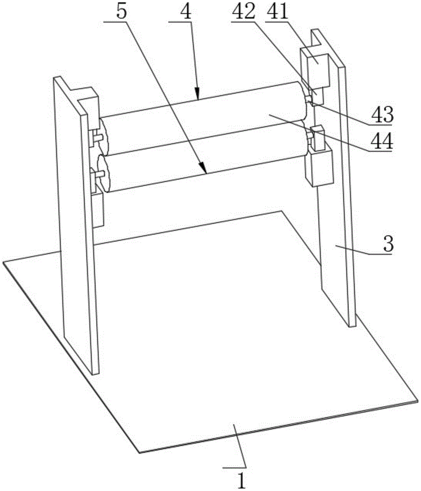
FIG. 2 is an isometric view of the vertically symmetrical electrostatic precipitator of the present invention;
FIG. 3 is a side view of the vertically symmetrical electrostatic precipitator of the present invention;
fig. 4 is an enlarged view of a single resilient adjustment slide bar structure at a of fig. 3 according to the present invention.
In the figure: the device comprises a frame 1, a feeding roller 2, a main roller 21, a supporting plate 22, a scraping plate 23, a side supporting plate 3, a first dust removal device 4, a fixed sleeve 41, an adjusting sliding groove 411, a square hole 412, a sliding rod 42, a sliding block 421, an adjusting spring 422, a rotating groove 423, a connecting shaft 43, an electrostatic dust removal roller 44 and a second dust removal device 5.
Detailed Description
Referring to fig. 1 and 2, a cloth rolling device includes a frame 1, and a feeding roller 2, a main roller 21, a supporting plate 22, a scraping plate 23, a first dust removing device 4, and a second dust removing device 5 which are arranged on the frame 1, wherein the frame 1, the feeding roller 2, the main roller 21, the supporting plate 22, and the scraping plate 23 are all the component structures of the rolling device for cloth production disclosed in the publication number CN 210162865U.
Referring to fig. 1, 2, 3 and 4, a frame 1 is welded with two side support plates 3, the two side support plates 3 are arranged symmetrically left and right about a vertical central axis of an electrostatic dust removal roller 44, the side support plates 3 are provided with a first dust removal device 4 and a second dust removal device 5, the first dust removal device 4 and the second dust removal device 5 are arranged symmetrically up and down, the first dust removal device 4 and the second dust removal device 5 respectively comprise a fixed sleeve 41, a sliding rod 42, a connecting shaft 43, an adjusting spring 422 and an electrostatic dust removal roller 44, the outer wall of a cylinder of the electrostatic dust removal roller 44 is provided with a common electrostatic dust removal brush, and electrostatic dust removal can be realized by an electrostatic adsorption principle.
Referring to fig. 1, 2, 3 and 4, a fixing sleeve 41 is welded and fixed on the side support plate 3, a sliding rod 42 is slidably sleeved in the fixing sleeve 41, a connecting shaft 43 is welded at two ends of the electrostatic dust removing roller 44, a rotating groove 423 is arranged at one end of the sliding rod 42 close to the connecting shaft 43, the rotating groove 423 is rotatably sleeved with the connecting shaft 43, the side cross sections of the rotating groove 423 and the connecting shaft 43 are circular structures, this structure has realized that electrostatic precipitator cylinder 44 is rotated by the drive of the lateral shifting cloth of in close contact with, is equipped with in the fixed sleeving 41 and adjusts spout 411, square hole 412 cup joints with slide bar 42 slides, the overlook hole cross-section of square hole 412 and the overlook cross-section of slide bar 42 are the square column structure that the phase-match cup jointed, the one end welding that slide bar 42 is located fixed sleeving 41 has slider 421, slider 421 and regulation spout 411 sliding connection, be provided with regulating spring 422 between slider 421 and the regulation spout 411 inside groove.
The working principle of the scheme is as follows: the cloth is through the blowing of material entering roller 2, then through layer board 22 surface translation left, strike off through the surface of scraper blade 23 again, continue the translation left after that, the cloth of translation left this moment can drive the electrostatic precipitator cylinder 44 of downside and top and bottom and rotate, the upper and lower terminal surface that the electrostatic precipitator cylinder 44 of downside can be followed the cloth this moment rolls, at rolling in-process, the static brush that presets on the cylinder outer wall of electrostatic precipitator cylinder 44 can carry out effective absorption through the electrostatic absorption principle and clear away the tiny dust that will adhere to the upper and lower surface of cloth, the cloth through dust removal can be beaten and roll up on main roll 21, realized carrying out roll formula electrostatic precipitator to the dust of the upper and lower surface adhesion of current cloth before beating to roll up through main roll 21, and then guaranteed the surface cleanliness factor that the cloth was beaten and was rolled up.
In addition, if the current cloth is thick, when the cloth passes between the upper and lower electrostatic precipitation rollers 44, the thick cloth will give the upper and lower electrostatic precipitation rollers 44 a pushing force to the upper and lower sides, taking the structure of the upper end sliding rod 42 as an example, the upper electrostatic precipitation roller 44 pushed upwards will drive the sliding rod 42 to slide upwards along the square hole 412, drive the sliding block 421 to slide upwards along the adjusting chute 411, at this time, the adjusting spring 422 will compress and deform and give the sliding rod 42 a downward resilience force, the resilience force is transmitted to the upper electrostatic precipitation roller 44, a rolling contact force between the upper electrostatic precipitation roller 44 and the thick cloth will be ensured, and further an electrostatic precipitation effect is ensured, the lower electrostatic precipitation roller 44 will receive the effect in the same way, the distance adjustment of the electrostatic precipitation rollers 44 symmetrical under the mountains can be performed for the cloth with different thicknesses, thereby the electrostatic precipitation effect on the cloth is ensured, the application range of the first dust removing device 4 and the second dust removing device 5 is improved.