CN1154520C - Inhaler for powdered medicaments - Google Patents
Inhaler for powdered medicaments Download PDFInfo
- Publication number
- CN1154520C CN1154520C CNB988055465A CN98805546A CN1154520C CN 1154520 C CN1154520 C CN 1154520C CN B988055465 A CNB988055465 A CN B988055465A CN 98805546 A CN98805546 A CN 98805546A CN 1154520 C CN1154520 C CN 1154520C
- Authority
- CN
- China
- Prior art keywords
- equipment
- tubular body
- cavity section
- user
- oral cavity
- Prior art date
- Legal status (The legal status is an assumption and is not a legal conclusion. Google has not performed a legal analysis and makes no representation as to the accuracy of the status listed.)
- Expired - Lifetime
Links
- 239000003814 drug Substances 0.000 title description 8
- 210000000214 mouth Anatomy 0.000 claims description 72
- 210000003928 nasal cavity Anatomy 0.000 claims description 28
- 239000000463 material Substances 0.000 claims description 24
- 239000000843 powder Substances 0.000 claims description 13
- 239000002775 capsule Substances 0.000 claims description 7
- 238000002360 preparation method Methods 0.000 claims description 7
- 210000004877 mucosa Anatomy 0.000 claims description 6
- 238000005520 cutting process Methods 0.000 claims description 4
- 238000011144 upstream manufacturing Methods 0.000 claims description 4
- 230000009471 action Effects 0.000 claims description 2
- 238000005452 bending Methods 0.000 claims description 2
- 238000012546 transfer Methods 0.000 claims description 2
- 241000220317 Rosa Species 0.000 claims 1
- 238000007664 blowing Methods 0.000 abstract description 6
- 239000000126 substance Substances 0.000 abstract description 6
- 230000035622 drinking Effects 0.000 abstract description 3
- 239000010902 straw Substances 0.000 abstract description 3
- 210000002396 uvula Anatomy 0.000 abstract description 3
- 210000004400 mucous membrane Anatomy 0.000 abstract 1
- 210000001331 nose Anatomy 0.000 description 15
- 238000000034 method Methods 0.000 description 11
- 239000003638 chemical reducing agent Substances 0.000 description 10
- 239000004033 plastic Substances 0.000 description 10
- 229920003023 plastic Polymers 0.000 description 10
- 239000011521 glass Substances 0.000 description 5
- 230000029058 respiratory gaseous exchange Effects 0.000 description 5
- 239000013543 active substance Substances 0.000 description 4
- 230000000694 effects Effects 0.000 description 4
- 230000006835 compression Effects 0.000 description 3
- 238000007906 compression Methods 0.000 description 3
- 239000006185 dispersion Substances 0.000 description 3
- 239000002552 dosage form Substances 0.000 description 3
- 210000003414 extremity Anatomy 0.000 description 3
- 238000001125 extrusion Methods 0.000 description 3
- 230000014509 gene expression Effects 0.000 description 3
- 238000004519 manufacturing process Methods 0.000 description 3
- 238000007789 sealing Methods 0.000 description 3
- 229960005486 vaccine Drugs 0.000 description 3
- 206010020751 Hypersensitivity Diseases 0.000 description 2
- 208000026935 allergic disease Diseases 0.000 description 2
- 230000004888 barrier function Effects 0.000 description 2
- 230000005540 biological transmission Effects 0.000 description 2
- 238000000071 blow moulding Methods 0.000 description 2
- 244000144987 brood Species 0.000 description 2
- 238000013461 design Methods 0.000 description 2
- 210000003811 finger Anatomy 0.000 description 2
- 238000011002 quantification Methods 0.000 description 2
- 208000031481 Pathologic Constriction Diseases 0.000 description 1
- 239000002313 adhesive film Substances 0.000 description 1
- 230000007815 allergy Effects 0.000 description 1
- 230000003321 amplification Effects 0.000 description 1
- 238000004458 analytical method Methods 0.000 description 1
- 230000002804 anti-anaphylactic effect Effects 0.000 description 1
- 230000001387 anti-histamine Effects 0.000 description 1
- 239000000739 antihistaminic agent Substances 0.000 description 1
- 230000015572 biosynthetic process Effects 0.000 description 1
- 238000005266 casting Methods 0.000 description 1
- 230000008859 change Effects 0.000 description 1
- 210000004081 cilia Anatomy 0.000 description 1
- 230000027288 circadian rhythm Effects 0.000 description 1
- 239000011248 coating agent Substances 0.000 description 1
- 238000000576 coating method Methods 0.000 description 1
- 239000003086 colorant Substances 0.000 description 1
- 238000012937 correction Methods 0.000 description 1
- 229940079593 drug Drugs 0.000 description 1
- 238000012377 drug delivery Methods 0.000 description 1
- 239000013013 elastic material Substances 0.000 description 1
- 238000005516 engineering process Methods 0.000 description 1
- 210000003238 esophagus Anatomy 0.000 description 1
- 210000005224 forefinger Anatomy 0.000 description 1
- 230000006870 function Effects 0.000 description 1
- 230000036541 health Effects 0.000 description 1
- 230000009610 hypersensitivity Effects 0.000 description 1
- 230000006872 improvement Effects 0.000 description 1
- 238000003780 insertion Methods 0.000 description 1
- 230000037431 insertion Effects 0.000 description 1
- 238000002372 labelling Methods 0.000 description 1
- 230000002045 lasting effect Effects 0.000 description 1
- 239000012528 membrane Substances 0.000 description 1
- 239000002184 metal Substances 0.000 description 1
- 238000003199 nucleic acid amplification method Methods 0.000 description 1
- 239000011236 particulate material Substances 0.000 description 1
- 239000012254 powdered material Substances 0.000 description 1
- 238000007639 printing Methods 0.000 description 1
- 230000008569 process Effects 0.000 description 1
- 230000005258 radioactive decay Effects 0.000 description 1
- 230000009467 reduction Effects 0.000 description 1
- 238000011160 research Methods 0.000 description 1
- 230000000241 respiratory effect Effects 0.000 description 1
- 230000033764 rhythmic process Effects 0.000 description 1
- 238000007788 roughening Methods 0.000 description 1
- 230000035807 sensation Effects 0.000 description 1
- 230000035939 shock Effects 0.000 description 1
- 210000004894 snout Anatomy 0.000 description 1
- 230000036262 stenosis Effects 0.000 description 1
- 208000037804 stenosis Diseases 0.000 description 1
- 230000000638 stimulation Effects 0.000 description 1
- 239000010409 thin film Substances 0.000 description 1
- 210000003813 thumb Anatomy 0.000 description 1
- 210000003437 trachea Anatomy 0.000 description 1
- 238000007666 vacuum forming Methods 0.000 description 1
Images


Classifications
-
- A—HUMAN NECESSITIES
- A61—MEDICAL OR VETERINARY SCIENCE; HYGIENE
- A61M—DEVICES FOR INTRODUCING MEDIA INTO, OR ONTO, THE BODY; DEVICES FOR TRANSDUCING BODY MEDIA OR FOR TAKING MEDIA FROM THE BODY; DEVICES FOR PRODUCING OR ENDING SLEEP OR STUPOR
- A61M15/00—Inhalators
- A61M15/08—Inhaling devices inserted into the nose
-
- A—HUMAN NECESSITIES
- A61—MEDICAL OR VETERINARY SCIENCE; HYGIENE
- A61M—DEVICES FOR INTRODUCING MEDIA INTO, OR ONTO, THE BODY; DEVICES FOR TRANSDUCING BODY MEDIA OR FOR TAKING MEDIA FROM THE BODY; DEVICES FOR PRODUCING OR ENDING SLEEP OR STUPOR
- A61M15/00—Inhalators
- A61M15/0091—Inhalators mechanically breath-triggered
- A61M15/0098—Activated by exhalation
-
- A—HUMAN NECESSITIES
- A61—MEDICAL OR VETERINARY SCIENCE; HYGIENE
- A61M—DEVICES FOR INTRODUCING MEDIA INTO, OR ONTO, THE BODY; DEVICES FOR TRANSDUCING BODY MEDIA OR FOR TAKING MEDIA FROM THE BODY; DEVICES FOR PRODUCING OR ENDING SLEEP OR STUPOR
- A61M2202/00—Special media to be introduced, removed or treated
- A61M2202/06—Solids
- A61M2202/064—Powder
-
- A—HUMAN NECESSITIES
- A61—MEDICAL OR VETERINARY SCIENCE; HYGIENE
- A61M—DEVICES FOR INTRODUCING MEDIA INTO, OR ONTO, THE BODY; DEVICES FOR TRANSDUCING BODY MEDIA OR FOR TAKING MEDIA FROM THE BODY; DEVICES FOR PRODUCING OR ENDING SLEEP OR STUPOR
- A61M2210/00—Anatomical parts of the body
- A61M2210/06—Head
- A61M2210/0625—Mouth
Abstract
A device for applying a powdered or particulate substance to a mucous membrane in a nostril comprises a tubular body (10) similar to a drinking straw. The tubular body has opposite end parts forming a mouthpiece (11) and a nasal piece (12) to be inserted between the lips and into the nostril, respectively, of a user. The mouthpiece (11) and the nasal piece (12) are interconnected by a bent or a bendable, preferably corrugated part (13). A dose of a powdered or particulate substance arranged within the tubular body (10) is transferred to the nostril when the user blows into the mouthpiece (11). A part of the mouthpiece is preferably deflated or compressed between a pair of fingers (35) of the user. The compressed part (34) is released when the user has started to blow forcefully into the compressed mouthpiece part which is thereby inflated. It has been found that the user will automatically close the connection between the nostrils and the throat by the uvula when blowing.
Description
Technical field
The present invention relates to a kind of in order to Powdered or particulate are imported people's a nostril or the method in two nostrils.As is generally known available air-flow is sent forth Powdered or particulate, air-flow is produced by the ball of compressed configuration at a pipe or flexible pipe one end, and pipe has an opposed free ends, and this end can insert the nostril.
Background technology
A kind of inhaler for powdered medicaments is disclosed among the WO 96/22802A1, comprise a tubular body that defines an inner flow passage, this passage inserts in the preparation of tubular body between the second opposed end of the nasal cavity section of first end in user nostril and said tubular body and extends longitudinally.
The invention provides this in order to Powdered or particulate are imported people's a nostril or the method in two nostrils, said method comprises that the material with dose is placed in the inner chamber of a tubular body, first opening of tubular body and intracavity inter-connection is inserted between people's two lips, second opening of tubular body and intracavity inter-connection is inserted said nostril, thereby and blow to first opening of tubular body and to form the air-flow that passes the tubular body inner chamber, in order to material is sent into the nostril.
Summary of the invention
In the method according to the invention, by people or patient to be treated utilize hers/his air-flow of exhalation causes and passes the required air-flow of tubular part inner chamber.Have been found that user is with the connection that automatically be closed by uvula between nostril and the throat when blowing.Thereby, prevented that basically Powdered or particulate from entering the trachea and the esophagus of user.So the material that utilizes method of the present invention almost all to be blown into the nostril all is coated on the intranarial mucosa.
Method of the present invention can utilize a tubular body to implement, and tubular body can have or give such shape, and promptly an one opening can insert between two lips of user, and opposing open end is then inserted the nostril of user.Thereby second end of said tubular body or opposite end can form a pair of adjacent opening that can insert two nostrils of user by bifurcated.
Before the two ends that tubular body is relative were inserted mouth and nostril respectively, the active substance of the suitable type of any kind of of a suitable dosage was inserted into the inner chamber of tubular body.These materials can be, for example, a kind of material of active antianaphylaxis or vaccine, as anti-pollen hypersensitivity, animal hair allergy, or the like.These materials or vaccine can be indivedual user preparations.On the other hand, this material can be in order to be coated in any medicine on the mucosa or other goods in the nostril, as a kind of antihistaminic.
In the time of in a user or patient insert first opening of tubular body his or his mouthful, patient's breathing may cause tubular body first opening by mistake to be subjected to slight negative pressure or superpressure.This may cause Powdered and particulate unexpectedly to enter tubular body and by moving that it is gone out.Determine that at said first opening of tubular body or near it at least one steam vent can reduce the risk that this accident of powdered substance moves.In any case, when user or patient insert first opening between two lips and prepare to blow that steam vent may be covered by lip or be positioned within the oral cavity of user when passing tubular body.
In the inner chamber of tubular body, constitute at least one cross section reducer and make a dosage of powder shape or particulate be placed on the downstream of reducer, said downstream be with respect to transmission Powdered or particulate to the direction of the air-flow in nostril.This cross section reducer will make user or patient blow more at full tilt and enter tubular body.Have, higher relatively by the air velocity in barrier or throat that reducer limited, this will help Powdered or particulate obtains good dispersion in air-flow again.When steam vent and near reducer is formed at first opening of tubular body or reducer preferably should be configured in steam vent it time downstream.
The efficient of tubular body can further improve by reducer being defined as deformable restrictor device when using the method according to this invention, and deformable restrictor device can move between a first throttle position and second position and be little basically by the throttling that restrictor device limited on the second position.Can be out of shape when the pressure differential of this deformable restrictor device in the lumen upstream of restrictor device and restrictor device downstream or tubular body outside reaches a predetermined value and move to the second nothing-throttling or little throttle position by the first throttle position.This means the powerful air-flow that when restrictor device moves to its second position by its primary importance, forms a burst in the inner chamber at tubular body.
The invention still further relates to a kind of equipment in order to coating powdered or particulate material on the intranarial mucosa of the user of equipment, said equipment comprises a tubular body that defines an inner flow passage, this passage inserts in the preparation of tubular body between the second opposed end of the nasal cavity section (12) of first end in user nostril and said tubular body and extends longitudinally, equipment according to the present invention is characterised in that second end of tubular body defines the oral cavity section that can insert between the user lips simultaneously, the length of tubular body and shape should make nasal cavity section and oral cavity section put into respectively simultaneously between the nostril and lips of user, thus user can to the end of the oral cavity of flow channel section blow and will be placed on Powdered or particulate in the tubular body flow channel with dispersive state transfer to the nostril.
Tubular body can have any mouth and intranarial suitable shape that makes oral cavity section and nasal cavity section correctly insert user respectively.
This can accomplish, for example, makes tubular body comprise a part intermediary bending or flexible.This means that tubular body can have maybe can give a corneous shape.As an example, tubular body or at least an one mid portion be to make by a kind of deformable or softish material.On the other hand, crooked and/or flexible part can be by adjacent, thereby that tubular body is made by hard relatively material is also flexible even the ripple that extends along periphery constitutes.Have been found that along the groove of the ripple inside of air-flow horizontal expansion and protuberance and can promote to pass the atomizing of particulate in the air-flow of gas channel and the dispersion of material.This effect at ripple longitudinally improves when axial cross section has zigzag fashion.This means that the bottom of damascene trench and the summit of ripple protuberance are relatively sharp-pointed.
Equipment according to the present invention is preferably disposable form.Therefore, equipment can comprise dosage of powder shape or the particulate that is placed in the gas channel.Equipment is once using and material has been sent on a people's the nostril or two intranarial mucosas, and equipment can be thrown away.Said material can have any help importing nostril and the form that is dispersed in the air-flow, for example a kind of antianaphylactic actively material or vaccine, a kind of medicine or medicine.
When tubular body had a dosage of powder shape or particulate, the opposed free ends of oral cavity section and nasal cavity section preferably was closed device respectively and seals or seal, and locking device will be removed or open before use equipment.This locking device can be a thin film removable or that split.In a preferred embodiment, in any case locking device comprises at least one cap cover part, be movably disposed within respectively on the free end of oral cavity section and nasal cavity section.So tubular body can seal with the sealing cap that is arranged on its each opposite end.In any case oral cavity section and nasal cavity section can be extended together and its free end closely be adjacent to put together before equipment uses when tubular body has a flexible mid portion.This means that tubular body becomes the U-type basically, will seal with a shared alternate cap cover part in the middle of the closely adjacent free end subsequently.
The inside and outside cross section of tubular body can be different along the length of tubular body.In a preferred embodiment, in any case tubular body has the shape of consistent basically inside and outside cross section along its length.Therefore, equipment of the present invention manufacturing very simply and can make and an appearance that drinking straw is identical.
For making the Powdered and particulate in the air-flow obtain good dispersion by gas channel the time, the speed of air must be relatively higher.Therefore, the cross-sectional area that gas channel had of tubular body preferably is no more than 75mm
2Preferably be not more than 70mm
2The cross-sectional area of gas channel is no more than 50mm in a preferred embodiment
2And be preferably 7-35mm
2Or about 20mm
2
Equipment according to the present invention can comprise also that in tubular body at least one is positioned at said first end or near the steam vent it.Equipment of the present invention also can be included in the formed restrictor device of at least one cross-section in the tubular body inner chamber, a dosage of powder shape or particulate is placed on the downstream of said restrictor device subsequently before equipment uses.This means that the air-flow that passes tubular body when user is blown by the oral cavity section will pass through restrictor device before the dose by Powdered or particulate.
Can between first throttle position and the second nothing-throttling or little throttle position, move thereby restrictor device is preferably deformable as mentioned above.This deformable restrictor device can comprise a flap valve, and flap valve covers in the cross section of tubular body inner chamber at least a portion when said primary importance, and deformable and moving on the position of little throttling.On the other hand, deformable restrictor device can comprise a check valve with any kind of a valve body, this valve is biased to one and cuts out or the position of throttling, is movable to one when first opening of tubular body or pressure that the oral cavity section is generated surpass this biasing force and opens or the position of little throttling and blow to enter user or patient.The valve body of check valve may be the form or the suchlike form of a flap valve.
Preferably, equipment of the present invention does not comprise and can bring a kind of risk because the cost that this separable part not only increases present device is returned user by separated portions on the tubular body.Therefore, no matter whether flap valve constitute a part of check valve, is preferably an integral part of tubular body wall.This can accomplish that for example, thereby flap valve is directly to form a steam vent in the upstream of flap valve by the inner chamber that cuts out and flex inward into tubular body on the tubular body wall.Thereby this hole preferably is formed at or directly make this hole can cover or be positioned at the oral cavity of the user of blowing to tubular body for the lips of user near the oral cavity section.
On the other hand, flap valve can be stretched to inner chamber or its opening of tubular body by the free margins of oral cavity section.
In a preferred embodiment, in any case restrictor device comprises the inside compressible part that maybe can squeeze on the tubular body wall.This compressible wall part can be a tubular body section longitudinally, and this section has small wall thickness and/or uses than tubular body remainder softness or have more elastic material and make.In the preferred embodiment, in any case the wall of tubular body has identical character basically along the length overall of tubular body.Tubular body all is compressible and " compressible portion " or " can squeeze part " labelling in addition along its length overall in this case, for example, utilizes different colors, printing, and annular knurl, roughening, or the like, perhaps " compressible portion " limited with fine rule etc.The embodiment that user or patient will use equipment of the present invention with Powdered or microgranular location transmission to his nostril or during two nostrils, he can pinch " compressible portion " of tubular body between his thumb and forefinger and exert pressure on this part, squeezes or make it flatly to fall.The nasal cavity section of equipment is inserted its nostril and the oral cavity section is put between his lips at user, he can blow to the oral cavity section at full tilt to form high pressure wherein.Thereby he can unclamp compressed portion and makes compression section inflation suddenly and expand and make air can freely pass the expedite inner chamber of tubular body subsequently.When user is blown compression section distortion simultaneously, form pressure in its oral cavity, make uvula close connection between nostril and the throat effectively.
Thereby being appreciated that restrictor device can comprise is suitable for blowing to pressure differential that tubular body first end forms is moved to any other type of its second little throttling or nothing-throttle position when surpassing a predetermined value by its first throttle position device at user between said first and second ends of tubular body.
Method and apparatus according to the invention also can be used for a brood lac-shape material is imported the nostril.This means Powdered or particulate can be for this brood lac-shape active substance.
The present invention also comprises a kind of in order to Powdered or particulate are sent forth the equipment in air-flow, said equipment comprises a tubular body, tubular body defines a flow channel therein and placed simultaneously a dosage of powder shape or microgranular active substance in flow channel, tubular body has the oral cavity section that can insert between the user lips at the one end, thereby make user blow into or to suck by the section end, oral cavity of flow channel sends said Powdered or particulate by in the air-flow of flow channel forth, in addition, equipment according to the present invention is characterised in that the cross section restrictor device is arranged in the upstream of potion active substance in the flow channel, restrictor device can move between one first sealing or throttle position and one second position by nothing that this restrictor device limited or basically little throttling, thereby restrictor device be suitable for user blow when entering section end, tubular body oral cavity formed pressure differential surpassing a predetermined value between the said oral cavity section of tubular body and nasal cavity section by its first throttle position move on to its second, on the position of little throttling.This equipment not only can be used for Powdered or microgranular goods are transferred to the nostril but also can be used as an inhaler.Tubular body and restrictor device can be any forms as described herein.
Description of drawings
Further describe the present invention now with reference to accompanying drawing, wherein
Fig. 1-3 has described three different embodiment of present device,
Fig. 4 is the side view of an amplification of equipment shown in Figure 3,
Fig. 5-8 has described another embodiment of present device,
Fig. 9 is the cross-sectional view of the magnification ratio of equipment shown in Figure 8,
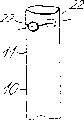
Figure 10 and 11 is two other embodiment of present device,
Figure 12 has the side view of magnification ratio of the oral cavity section embodiment of steam vent for present device,
Figure 13 is another embodiment of oral cavity section, wherein has a steam vent and a flap valve that puts in oral cavity section inner chamber,
Figure 14 is an oral cavity section embodiment who has the flap valve that is extended by oral cavity section free margins,
Figure 15 is another embodiment of oral cavity section, wherein has a steam vent and a tube wall part that puts in oral cavity section inner chamber,
Figure 16 is another embodiment that comprises the oral cavity section of an independent check valve,
Figure 17 is the oral cavity section embodiment with the wall part under inwardly flat,
Figure 18 is a side view, and the equipment that expression has an oral cavity section as shown in figure 17 is how for the user clamping,
Figure 19 represent equipment shown in Figure 180 how to insert the nostril of user and lips and
Shown in Figure 20 identical with Figure 19, pass the situation of oral cavity section but blow for user.
The specific embodiment
How Fig. 1 explanation uses an equipment of the present invention a dosage of powder shape or particulate to be imported the nostril of user.Equipment 10 shown in Fig. 1 is a tubular body, and it can be by rubber, cellulosic material, and glass or plastic monoblock are made, and for example utilize blow moulding.That equipment is preferably disposable type and comprise an oral cavity section 11 and the nasal cavity section 12 that can insert the user nostril that to insert between the user lips respectively in two relative ends.Oral cavity section 11 is connected by a mid portion 13 with nasal cavity section 12.The formation of mid portion is substantially as same arc section in the embodiment shown in fig. 1.
The tubular body of constitution equipment 10 can have any suitable shape of cross section.When cross section was circle, its internal diameter for example, can be 3-8mm.Tubular equipment 10 can comprise a dosage of powder shape or particulate 14.Before use equipment, relative two openings of tubular body are sealed by the locking device of a pair of movably cap or any other type, and this locking device can pierce through or remove.
When using equipment shown in Figure 1, take off locking device by two opposite ends of tubular equipment.Then, respectively with between the lips of oral cavity section 11 and nasal cavity section 12 insertion user and nostril, as shown in Figure 1.At this moment thereby user is blown and to be passed oral cavity section 11 and make powdered substance 14 send forth in passing the air-flow of tubular equipment and be transferred to the nostril.
An embodiment of Fig. 3 and 4 expression present devices, this equipment is made up of a plurality of parts.So in Fig. 3 and 4, mid portion 13 defines an inner chamber 15, inner chamber is open to respectively in order to accept the socket of the independent oral cavity section that forms 11 and one or two nasal cavity section 12.Interlude 13 shown in Fig. 3 and 4 can be made with blow moulding and oral cavity section 11 and one or two nasal cavity section 12 can be the straight lengths of being made by glass or plastic material by plastic material.Mid portion is reusable because these pipeline sections are removably to be connected on the mid portion 13, and they are preferably disposable.
As shown in Figure 4, equipment can comprise a pair of nasal cavity section 12 and an independent oral cavity section 11.On the other hand, equipment can include only a nasal cavity section.The mobile turbulent flow that forms can be improved Powdered or particulate sending forth in passing the air-flow of tubular equipment in use thereby the shape of mid portion 13 inner chambers 15 preferably can make the air that passes inner chamber.
Tubular equipment shown in Figure 5 is an integral manufacturing, for example with glass or plastics, and is disposable type, wherein comprises a dosage of powder shape or particulate 14.Therefore, before using the opposite end of tubular body 10 by aforesaid cap or other movably the locking device (not shown) seal.In Fig. 5, thus mid portion 13 for have a circle or more the helical form of multi-turn or circle improved powdered substance in use and entered sending forth in the air-flow that passes in the tubular equipment 10.
Fig. 6 is the embodiment of tubular equipment 10 of the present invention, the similar drinking straw of its shape.Equipment comprises relative, the end sections that constitutes oral cavity section 11 and nasal cavity section 12 respectively of the shape that is in line basically.These collinear end sections are connect by an integrally formed mid portion 13, and mid portion has many ripples that extend along periphery, and these ripples are preferably has sharp-pointed relatively cutting edge of a knife or a sword and the type of paddy.Owing to have these ripples, mid portion becomes flexible and ripple and also causes passing turbulent flow in the tubular equipment air-flow.So the sending forth as previously mentioned of Powdered or particulate in the air-flow improves.Before use, tubular equipment can comprise the material 14 of a dosage, and two opposite ends of foregoing equipment can be sealed simultaneously.
Embodiment shown in Figure 10 can be made by hard relatively material, as plastics or glass, shown in shape as making as softish plastics or rubber by deformable material.Under one situation of back, it is collinear pipeline section basically that tubular equipment can be made with extrusion molding, the shape shown in this pipeline section can curve before use.
Embodiment shown in Figure 10 can be made by hard relatively material, as plastics or glass, shown in shape as making as softish plastics or rubber by deformable material.Under one situation of back, it is collinear pipeline section basically that tubular equipment can be made with extrusion molding, the shape shown in this pipeline section can curve before use.
Figure 11 represents a predetermined embodiment that will use several.Be divided into the two parts that constitute oral cavity section 11 and nasal cavity section 12 respectively with blowing the tubular equipment 10 that casting manufactures.These two parts can be hinged or telescopically connect each other and thereby a capsule 18 that is comprising a dosage of powder shape or particulate can be filled in mid portion 13.Equipment can comprise pin or the cutter (not shown) that pierces through, in order to automatically to open capsule when two independent parts are closed.In the embodiment shown in fig. 11, on the wall of mid portion 13, form a opening 19 in order to fill in capsule 18.Cap assembly of mid portion 13 usefulness 20 surrounds, and these parts can rotate between the two positions around mid portion, exposes opening 19 on position therein and is closed in another position upper shed.When cap assembly moves to its detent position one by spring starting pierce through or cutting part 21 can automatically be opened capsule 18.
Figure 12-17 is with the various embodiment of picture specification oral cavity section 11 external freedom ends.A pair of in Figure 12 is that the opening of relatively arranging 22 is formed at oral cavity section 11 near on its free-ended wall in principle.If people or patient breathe out by the opening of oral cavity section 11 or when sucking absent-mindedly in the process of preparing use equipment, the respiratory air flow by oral cavity section 11 openings can pass opening 22.In any case, user with the free end of oral cavity section 11 be placed on opening 22 is capped on or be positioned at the oral cavity and when firmly blowing opening 22 will can not influence air-flow by tubular body 10 inner chambers.
Figure 13 represents an embodiment, and one of them opening 23 is to cut out a flap valve 24 on the wall by oral cavity section 11 to form, and flap valve 24 still is connected on the wall of tubular part by the hinge part 25 of the medial extremity of opening 23.Thereby the crooked tubular part that enters of flap valve 24 has also partly limited passage wherein across the extension of tubular part inner chamber.If user sucks slightly or breathes out and will can or seldom not exert an influence by the opening of oral cavity section 11, because the existence of opening 23 and flap valve 24 is arranged.In any case when user is put into oral cavity section free end between the lips and when oral cavity section opening is firmly blown, flap valve 24 will get out of the way and open wide the flow channel by tubular body 10 rapidly.Thereby this will form a powerful compression shock and make Powdered or microgranular goods 14 send forth effectively in air-flow and be blown into the nostril of user.
In the embodiment shown in fig. 14, flap valve 24 is connected on the oral cavity section 11 by the hinge part 25 that is positioned on oral cavity section 11 free margins.In addition, function embodiment illustrated in fig. 14 is basically with shown in Figure 13 identical.
Figure 15 is an embodiment, be by cutting out a pair of separating each other on the wall of oral cavity section at formed steam vent 26 on the oral cavity section 11 wherein, the seam that is parallel to each other also will push inward snout cavity section 11 inner chambers by the wall part 27 of the band-shape that is limited between two seams and form.Therefore, wall part 27 forms flow barrier parts.Embodiment illustrated in fig. 15ly play the effect identical in a similar fashion with Figure 13 and 14.
Figure 16 is an embodiment, and one of them independent check valve 28 comprises movably valve body 30 of a ring-shaped valve seats 29 and flap valve-shape, this valve be connected in the oral cavity section 11 near its free end.If patient blows into oral cavity section 11 but when sucking by tubular body 10 mistakenly, check valve 28 can prevent to pass tubular body 10 along the opposite way round airflow flowing.In addition, valve member 30 can be with the elastic force bias voltage to its position of closing, thus only when crossing over check valve 28 and form predetermined pressure differential check valve just can be opened.
Oral cavity shown in Figure 17 section 10 comprises a manned valve 31.This mechanical valve 31 is formed by the deformable wall part 32 of positioned opposite, and this part for example, can be limited with fine rule or curved line 33.When in will be as Figure 17, being applied on the oral cavity section 11, a reducer or stenosis area 36 in oral cavity section 11, have been formed with arrow 34 represented direction pressure in opposite directions with pair of finger 35 (referring to Figure 18).This reducer 36 can prevent because neglectful suction or the action that blows out cause the air-flow unintentionally that passes tubular body 10.
When use has the equipment 10 of the present invention of oral cavity section 11 as shown in figure 17, thereby the deformable wall part 32 of equipment forms a reducer 36 with pair of finger 35 clampings as shown in figure 18.Oral cavity section 11 and nasal cavity section 12 are put between the lips of user respectively and the nostril subsequently, and as shown in figure 19, at this moment deformable segment 32 still is compressed.Deformable segment 32 is released when user firmly is blown into oral cavity section 11, as shown in figure 20.Thereby the pressure that forms in oral cavity section 11 porch is enough to make the wall part 32 rapid inflations of distortion to make it be returned to its initial position.So form an instantaneous powerful air-flow that passes tubular equipment 10.Powdered or the microgranular goods 14 of potion are sent forth immediately in air-flow and are carried by air-flow, and Powdered or particulate are transferred to the nostril.
Embodiment
The attached form of powdered substance is assessed by two different equipment with the removing characteristic after dispensing.
Preface
Can change into various dosage forms are coated on the different zone of nose by removing the required time of a kind of dosage form on the nose.Nose is nothing-cilium zone, therefore, delivers at supratip medicine and throwing and will retain the long time at nasal cavity the breathing or the comparing of olfactory sensation zone of nose.Using different administration apparatus is possible for producing checkout time far from it with a kind of pharmaceutical dosage form.An embodiment (following will being referred to as " equipment of the present invention ") of basis present device as shown in Figure 6 and traditional being used in this example contrasts aspect the cycle at nose the equipment (following will being referred to as " prior art level ") of nose delivery dry powder.
The nose cycle is many phenomenons of being admitted, and produces promptly that one-sided nose blocks and air is mobile that the alternative phenomenon of the rhythm and pace of moving things arranged.For studying the drug delivery of nose effectively, obtaining each volunteer is very important about the information in nose cycle, because the nose cycle is influential for the removing on the mucomembranous cilium.
Method
For studying removing characteristic and the attached form that different delivery equipment is produced, according to for each course of treatment at interval the cross-over design of carrying out two research days in a week radiolabel powder is delivered volunteer to one group of 6 health.The peak value that before delivery the nose in every each nostril of volunteer is sucked air-flow measures.Resulting data are in order to draw every volunteer's circadian rhythm, so that various dosage are shipped to patient's nasal openings.
The prior art level
The volunteer carries out twice deep breathing by the nostril and keeps the end of equipment in the patient nostril simultaneously.The content of equipment (10mg, about 1MBq) is sent to the mucomembranous surface in patient nostril.
The present invention
The volunteer puts into the end of nose with the long limb of equipment and around manomelia mouth is closed.One fast, and powerful air-flow is delivered to the content (10mg, about 1MBq) of equipment on the mucomembranous surface in patient nostril.
Adhere to and the removing subsequently of different nose delivery systems all used Maxi Camera II gamma camera (General Electric) to carry out the gamma scintigraphy and followed the tracks of.The position of volunteer's nose is fixed on the collimator of gamma camera with the template of a particular design.After medication and at the back 180 minutes appropriate time of dispensing, take later motionless side view (lasting 60 seconds) at interval.Image goes on record and is used as subsequently analysis and quantification.
The result
Quantification by the resulting data of volunteer comprises the interesting areas of determining around nasal cavity and throat.By the count rate on each interesting areas (ROI), pass through correction to radioactive decay and background, be represented as a ratio of the highest one minute counting subsequently, the highest counting is generally at the later image in nasal cavity ROI immediate record of administration.Here it is, gives the highest count rate with 100% value, subsequently promptly in order to the percent value of the count rate of time point after calculating.
Preparation is recently to assess with respect to the percentage of time reduction with the activity of preparation among each volunteer by the removing of nasal cavity like this.Utilize this to clear data, 50% ROI by nasal cavity that calculates for preparation with regard to each volunteer is eliminated the required time.In addition, the assessment by the attached form that this equipment produced is by determining an interested area around the initial scene of adhering to and counting the computer unit that is capped.
Volunteer's prior art level equipment of the present invention
Identifier T
50Bond area T
50Bond area
(minute) (unit number) (minute) (unit number)
001 170 41 158 35
004 43 48 171 56
005 123 37 153 29
007 84 36 101 28
009 110 34 139 25
010 144 36 48 27
Average 112 39 128 33
Standard error ± ± 18 ± 2 ± 18 ± 5
Conclusion/observed result
Checkout time and bond area that equipment of the present invention and prior art level are produced do not have evident difference each other.
Equipment emptying of the present invention is fabulous, only needs once powerful air-flow equipment can be emptied completely.By comparison, existing technical merit is delivered entire contents often needs twice breathing air inlet.
Believe that equipment of the present invention is in full force and effect to need a simple flow valve in order to make.Equipment emptying of the present invention is so good so that all be enough to make equipment along wrong route emptying inlet port once will long limb put into the nostril around the air-breathing of any breathing of manomelia.
The volunteer reports after using equipment of the present invention seldom has stimulation to mucosa.
Should be appreciated that and to form various other embodiment within the scope of the invention.Therefore, all available suitable mode of the disclosed any feature of the embodiment that illustrates is in conjunction with the accompanying drawings exchanged or is made up.
Claims (20)
1. one kind in order to the equipment on the intranarial mucosa of user that Powdered or particulate is shipped to this equipment, said equipment comprises a tubular body that defines an inner flow passage, this passage inserts in the preparation of tubular body between the second opposed end of the nasal cavity section (12) of first end in user nostril and said tubular body and extends longitudinally
Second end that it is characterized in that tubular body defines the oral cavity section (11) that can insert between the user lips, the length of tubular body and shape should make nasal cavity section and oral cavity section put into respectively simultaneously between the nostril and lips of user, thus user can to the end of the oral cavity of flow channel section blow and will be placed on Powdered or particulate in the tubular body flow channel with dispersive state transfer to the nostril.
2. according to said equipment in the claim 1, it is characterized in that tubular body comprises a part intermediary bending and/or flexible.
3. according to said equipment in the claim 2, it is characterized in that crooked and/or flexible part comprises the adjacent ripple that extends along periphery.
4. according to said equipment in the claim 3, it is characterized in that having jagged external shape by the ripple of looking of axial cross section longitudinally.
5. according to said equipment in the claim 2, it is characterized in that sweep comprises that one has a circle or multiturn, or the threaded portion of a circle or multi-turn.
6. according to said equipment in the claim 2, it is characterized in that sweep comprises an independent part, be formed with socket on it, in order to accept an independent oral cavity section and at least one independent nasal cavity section movably.
7. according to the said equipment of claim 2, it is characterized in that sweep is openable, thereby the capsule that contains a said material of dosage can be filled in tubular body, equipment disposes when capsule is filled in tubular body in order to cut or to pierce through the device of capsule wall.
8. according to the said equipment of claim 3, also comprise the dosage of powder shape or the particulate that are placed in the flow channel.
9. according to the said equipment of claim 2, the mid portion that it is characterized in that tubular body is flexible, and oral cavity section and nasal cavity section are extended simultaneously and its free end is being placed on the tight position adjacent before the use equipment.
10. according to the said equipment of claim 1, it is characterized in that the cross-sectional area that flow channel had of tubular body is no more than 75mm
2
11. according to said equipment in the claim 10, the cross-sectional area that it is characterized in that flow channel is 7-35mm
2
12., in tubular body, also comprise causing turbulent device according to the said equipment of claim 1.
13., it is characterized in that causing that turbulent device comprises is arranged in the intravital helical thread shape of tubulose parts according to said equipment in the claim 12.
14. according to the said equipment of claim 1, also be included in the tubular body wall on said first end of oral cavity section or near at least one steam vent of setting.
15. said according to Claim 8 equipment also is included in the restrictor device that forms the throttling at least one cross section in the tubular body inner chamber, a dosage of powder shape or particulate are placed in the downstream at said restrictor device before equipment uses.
16. according to said equipment in the claim 15, thereby it is characterized in that restrictor device is deformable can moving between the first throttle position and second throttle position, the throttling action that restrictor device rose on second throttle position is very little.
17. according to said equipment in the claim 16, it is characterized in that restrictor device comprises a flap valve, flap valve covers the part cross section of tubular body inner chamber at least when its said first throttle position.
18. according to said equipment in the claim 17, it is characterized in that flap valve by cutting out on the tubular body wall, and curve inwardly and enter the inner chamber of tubular body, thereby define a steam vent in the upstream that is right after flap valve.
19., it is characterized in that restrictor device comprises that inwardly can oppressing maybe of tubular body wall can squeeze part according to said equipment in the claim 15.
20. according to any said equipment among the claim 16-19, it is characterized in that restrictor device blows when entering that thereby formed pressure differential surpasses a predetermined value between said first and second ends of tubular body second end at tubular body at user, be suitable for moving on to the second less throttle position by its first throttle position.
Applications Claiming Priority (3)
| Application Number | Priority Date | Filing Date | Title |
|---|---|---|---|
| DK606/1997 | 1997-05-27 | ||
| DK60697 | 1997-05-27 | ||
| DK606/97 | 1997-05-27 |
Publications (2)
| Publication Number | Publication Date |
|---|---|
| CN1258223A CN1258223A (en) | 2000-06-28 |
| CN1154520C true CN1154520C (en) | 2004-06-23 |
Family
ID=8095483
Family Applications (1)
| Application Number | Title | Priority Date | Filing Date |
|---|---|---|---|
| CNB988055465A Expired - Lifetime CN1154520C (en) | 1997-05-27 | 1998-05-26 | Inhaler for powdered medicaments |
Country Status (25)
| Country | Link |
|---|---|
| US (2) | US6648848B1 (en) |
| EP (1) | EP0986413B1 (en) |
| JP (1) | JP2001526577A (en) |
| KR (1) | KR100467058B1 (en) |
| CN (1) | CN1154520C (en) |
| AT (1) | ATE274956T1 (en) |
| AU (1) | AU730843B2 (en) |
| BR (1) | BR9809499A (en) |
| CA (1) | CA2291005C (en) |
| CZ (1) | CZ296017B6 (en) |
| DE (1) | DE69825995T2 (en) |
| DK (1) | DK0986413T3 (en) |
| EA (1) | EA002193B1 (en) |
| ES (1) | ES2229496T3 (en) |
| HK (1) | HK1027300A1 (en) |
| HU (1) | HU222692B1 (en) |
| NO (1) | NO332022B1 (en) |
| NZ (1) | NZ501157A (en) |
| PL (1) | PL189855B1 (en) |
| PT (1) | PT986413E (en) |
| SI (1) | SI0986413T1 (en) |
| SK (1) | SK286510B6 (en) |
| TR (1) | TR199902899T2 (en) |
| UA (1) | UA52755C2 (en) |
| WO (1) | WO1998053869A1 (en) |
Families Citing this family (62)
| Publication number | Priority date | Publication date | Assignee | Title |
|---|---|---|---|---|
| CN1736502A (en) | 1999-03-03 | 2006-02-22 | 奥普蒂诺斯公司 | Nasal delivery method |
| GB0114272D0 (en) * | 2001-06-12 | 2001-08-01 | Optinose As | Nasal delivery device |
| GB0121568D0 (en) * | 2001-09-06 | 2001-10-24 | Optinose As | Nasal delivery device |
| ZA200306564B (en) * | 2001-02-26 | 2004-10-15 | Optinose As | Nasal devices. |
| WO2002078774A1 (en) * | 2001-03-28 | 2002-10-10 | Direct-Haler A/S | Compliance system for drug delivery |
| AU2002331064B2 (en) | 2001-08-10 | 2007-08-23 | Palatin Technologies, Inc. | Peptidomimetics of biologically active metallopeptides |
| US7456184B2 (en) | 2003-05-01 | 2008-11-25 | Palatin Technologies Inc. | Melanocortin receptor-specific compounds |
| US7718802B2 (en) | 2001-08-10 | 2010-05-18 | Palatin Technologies, Inc. | Substituted melanocortin receptor-specific piperazine compounds |
| US7655658B2 (en) | 2001-08-10 | 2010-02-02 | Palatin Technologies, Inc. | Thieno [2,3-D]pyrimidine-2,4-dione melanocortin-specific compounds |
| US7732451B2 (en) | 2001-08-10 | 2010-06-08 | Palatin Technologies, Inc. | Naphthalene-containing melanocortin receptor-specific small molecule |
| JP4290009B2 (en) | 2001-11-22 | 2009-07-01 | フライドリング・アンゲラ | Inhaler controlled by breathing system for dry powder |
| GB0207422D0 (en) | 2002-03-28 | 2002-05-08 | Optinose As | Nasal devices |
| GB0215270D0 (en) | 2002-07-02 | 2002-08-14 | Optinose As | Nasal devices |
| KR100502636B1 (en) * | 2003-03-14 | 2005-07-20 | 주식회사 서일 | Straw |
| US7968548B2 (en) * | 2003-05-01 | 2011-06-28 | Palatin Technologies, Inc. | Melanocortin receptor-specific piperazine compounds with diamine groups |
| US7727991B2 (en) | 2003-05-01 | 2010-06-01 | Palatin Technologies, Inc. | Substituted melanocortin receptor-specific single acyl piperazine compounds |
| US7727990B2 (en) | 2003-05-01 | 2010-06-01 | Palatin Technologies, Inc. | Melanocortin receptor-specific piperazine and keto-piperazine compounds |
| GB0311570D0 (en) | 2003-05-20 | 2003-06-25 | Optinose As | Delivery device and method |
| GB0319119D0 (en) | 2003-08-14 | 2003-09-17 | Optinose As | Delivery devices |
| GB0320171D0 (en) | 2003-08-28 | 2003-10-01 | Optinose As | Delivery devices |
| EP1675637B1 (en) * | 2003-10-21 | 2017-07-26 | Direct-Haler A/S | An inhaler |
| US7709484B1 (en) | 2004-04-19 | 2010-05-04 | Palatin Technologies, Inc. | Substituted melanocortin receptor-specific piperazine compounds |
| GB0420513D0 (en) * | 2004-09-15 | 2004-10-20 | Optinose As | Powder delivery devices |
| GB0503738D0 (en) | 2005-02-23 | 2005-03-30 | Optinose As | Powder delivery devices |
| US20060289006A1 (en) * | 2005-06-27 | 2006-12-28 | Kos Life Sciences, Inc. | Breath actuated nasal drug delivery system |
| JP3787636B1 (en) * | 2005-08-26 | 2006-06-21 | 国立大学法人 岡山大学 | Nostril plug for improving articulation disorder |
| CA2642608C (en) | 2006-01-19 | 2018-05-29 | Optinose As | Nasal administration |
| GB0604444D0 (en) | 2006-03-06 | 2006-04-12 | Optinose As | Nasal devices |
| GB0605799D0 (en) | 2006-03-23 | 2006-05-03 | Optinose As | Nasal delivery devices |
| GB2438834A (en) | 2006-06-08 | 2007-12-12 | Optinose As | Intranasal protein administration |
| GB2440316A (en) | 2006-07-25 | 2008-01-30 | Optinose As | Nasal inhaler with scrubber |
| US7834017B2 (en) | 2006-08-11 | 2010-11-16 | Palatin Technologies, Inc. | Diamine-containing, tetra-substituted piperazine compounds having identical 1- and 4-substituents |
| GB2476731B (en) * | 2006-11-28 | 2011-08-24 | Optinose As | Delivery devices |
| GB0623732D0 (en) | 2006-11-28 | 2007-01-10 | Optinose As | Powder delivery devices |
| GB0623731D0 (en) | 2006-11-28 | 2007-01-10 | Optinose As | Delivery device |
| GB0623728D0 (en) | 2006-11-28 | 2007-01-10 | Optinose As | Delivery devices |
| GB2448193A (en) | 2007-04-05 | 2008-10-08 | Optinose As | Nasal delivery device |
| GB2448183A (en) | 2007-04-05 | 2008-10-08 | Optinose As | Nasal powder delivery device |
| GB0719299D0 (en) | 2007-10-03 | 2007-11-14 | Optinose As | Nasal delivery devices |
| EP2534957B1 (en) | 2007-12-14 | 2015-05-27 | AeroDesigns, Inc | Delivering aerosolizable products |
| FR2954707B1 (en) * | 2009-12-28 | 2016-01-08 | Diffusion Tech Francaise Sarl | ORAL AEROSOL DELIVERY DEVICE USING A RHINOPHARYNGEAL, NASAL OR NASOSINUSIAN VISION |
| GB201015371D0 (en) | 2010-09-14 | 2010-10-27 | Optinose As | Nasal delivery |
| WO2012123819A1 (en) | 2011-03-15 | 2012-09-20 | Optinose As Et Al | Nasal delivery |
| JP6218747B2 (en) * | 2011-12-16 | 2017-10-25 | インドシス リミテッド | Drug unit dose cartridge and delivery device |
| US10525216B2 (en) | 2012-02-21 | 2020-01-07 | Respira Therapeutics, Inc. | Powder dispersion methods and devices |
| MX352029B (en) * | 2012-02-24 | 2017-11-07 | Optinose As | Nasal delivery devices. |
| WO2013124492A1 (en) | 2012-02-24 | 2013-08-29 | Optinose As | Nasal delivery devices |
| DK2817053T3 (en) | 2012-02-24 | 2018-08-13 | Optinose As | NATIONAL SUBMISSION DEVICES |
| US10099024B2 (en) | 2012-06-28 | 2018-10-16 | The United States Of America, As Represented By The Secretary, Department Of Health And Human Services | Nasal dry powder delivery system for vaccines and other treatment agents |
| NO2870072T3 (en) | 2012-07-05 | 2018-01-20 | ||
| CN104619604B (en) * | 2012-07-30 | 2017-04-05 | P.C.O.A.设备有限公司 | For accommodating and distributing the container of solid medicinal pill |
| US11554229B2 (en) | 2013-03-26 | 2023-01-17 | OptiNose Inc. | Nasal administration |
| USD761951S1 (en) | 2013-05-23 | 2016-07-19 | Optinose As | Nosepiece unit |
| CN103349806A (en) * | 2013-07-05 | 2013-10-16 | 申瑞娟 | Respiratory tract inflammation therapy device |
| US9925348B2 (en) * | 2013-07-17 | 2018-03-27 | Upods, Llc | Gas delivery device |
| MX2017000441A (en) | 2014-07-11 | 2017-04-27 | Philip Morris Products Sa | Aerosol-generating system with improved air flow control. |
| ES2813442T3 (en) | 2014-11-19 | 2021-03-23 | Optinose As | Intranasal administration |
| NZ706864A (en) | 2015-04-09 | 2016-07-29 | Aft Pharmaceuticals Ltd | A nasal medication delivery device |
| CA3012477C (en) * | 2016-02-04 | 2019-09-24 | Ip Med, Inc. | Medicament delivery device and method |
| KR102450400B1 (en) | 2016-03-28 | 2022-10-04 | 쓰리엠 이노베이티브 프로퍼티즈 캄파니 | Respiratory compatibility test sealing device and method |
| WO2018031278A1 (en) * | 2016-08-12 | 2018-02-15 | Upods, Llc | Gas delivery device |
| CN109289115B (en) * | 2018-10-26 | 2021-04-06 | 万秀芳 | Tonsil inflammation medicine feeding device |
Family Cites Families (28)
| Publication number | Priority date | Publication date | Assignee | Title |
|---|---|---|---|---|
| US419942A (en) * | 1890-01-21 | Insufflator | ||
| US429321A (en) * | 1890-06-03 | Inhaler | ||
| US424321A (en) * | 1890-03-25 | Game apparatus | ||
| US658436A (en) * | 1900-05-28 | 1900-09-25 | Hans Hennerich Groth | Insufflator. |
| US707445A (en) * | 1902-04-10 | 1902-08-19 | John Howard Mcculloch | Inhaler. |
| US723738A (en) * | 1902-06-05 | 1903-03-24 | August K Schulte | Inhaler. |
| US746749A (en) * | 1903-03-18 | 1903-12-15 | George E Seidel | Nasal medicator. |
| US781428A (en) * | 1904-07-28 | 1905-01-31 | Sheridan J Hutchins | Inhaler, injector, and medicator. |
| US794641A (en) * | 1905-03-06 | 1905-07-11 | Alfred H Ramey | Inhaler. |
| US867827A (en) * | 1906-05-14 | 1907-10-08 | John Howard Mcculloch | Inhaler. |
| US902832A (en) * | 1907-09-20 | 1908-11-03 | Edward F Philbrook | Inhaler. |
| US1375325A (en) * | 1920-06-29 | 1921-04-19 | Schaefer William Henry | Inhaler |
| US1540274A (en) | 1924-03-28 | 1925-06-02 | William J Moore | Nasal inhaler |
| US2021332A (en) | 1931-11-28 | 1935-11-19 | Silten Ernst | Inhalation apparatus |
| US2086588A (en) * | 1935-11-18 | 1937-07-13 | Joseph J Tobin | Vaporizing applicator |
| US2693805A (en) * | 1947-03-08 | 1954-11-09 | George V Taplin | Apparatus for administering therapeutic agents |
| GB1242211A (en) * | 1967-08-08 | 1971-08-11 | Fisons Pharmaceuticals Ltd | Pharmaceutical composition |
| US4216768A (en) * | 1978-03-23 | 1980-08-12 | Whitfield Jack | Device for inhaling powdered substance |
| US4265236A (en) * | 1980-03-31 | 1981-05-05 | Pacella Angelo M | Portable inhalator device |
| US5046493A (en) * | 1988-02-16 | 1991-09-10 | James Kropkowski | Nasal dispenser |
| US5167242A (en) | 1990-06-08 | 1992-12-01 | Kabi Pharmacia Aktiebolaq | Nicotine-impermeable container and method of fabricating the same |
| US5373841A (en) * | 1992-02-04 | 1994-12-20 | Kyllonen; David M. | Self-operated nasal humidifier |
| GB2270293A (en) | 1992-09-05 | 1994-03-09 | Medix Ltd | Drug dispensing system |
| FR2696080B1 (en) | 1992-09-30 | 1994-12-23 | Jesus Covarrubias | Cigarette filter for administration of taurine by inhalation. |
| GB9415722D0 (en) | 1994-08-03 | 1994-09-21 | Fxk Patents Ltd | Breathing equipment |
| NZ298384A (en) | 1995-01-23 | 1998-07-28 | Direct Haler As | Inhaler - single dose of particulate substance arranged in air flow passage |
| SE506208C2 (en) * | 1995-07-05 | 1997-11-24 | Aerocrine Systems Kb | Device for collecting gas from the upper respiratory tract and delivering this gas to the inhalation air in a respirator |
| US6074673A (en) * | 1996-04-22 | 2000-06-13 | Guillen; Manuel | Slow-release, self-absorbing, drug delivery system |
-
1998
- 1998-05-26 WO PCT/DK1998/000214 patent/WO1998053869A1/en active IP Right Grant
- 1998-05-26 DK DK98924061T patent/DK0986413T3/en active
- 1998-05-26 PT PT98924061T patent/PT986413E/en unknown
- 1998-05-26 BR BR9809499-8A patent/BR9809499A/en not_active IP Right Cessation
- 1998-05-26 UA UA99127070A patent/UA52755C2/en unknown
- 1998-05-26 CZ CZ19994177A patent/CZ296017B6/en not_active IP Right Cessation
- 1998-05-26 ES ES98924061T patent/ES2229496T3/en not_active Expired - Lifetime
- 1998-05-26 EP EP98924061A patent/EP0986413B1/en not_active Revoked
- 1998-05-26 US US09/424,085 patent/US6648848B1/en not_active Expired - Lifetime
- 1998-05-26 EA EA199901083A patent/EA002193B1/en not_active IP Right Cessation
- 1998-05-26 SI SI9830683T patent/SI0986413T1/en unknown
- 1998-05-26 TR TR1999/02899T patent/TR199902899T2/en unknown
- 1998-05-26 AU AU76392/98A patent/AU730843B2/en not_active Expired
- 1998-05-26 DE DE69825995T patent/DE69825995T2/en not_active Expired - Lifetime
- 1998-05-26 CN CNB988055465A patent/CN1154520C/en not_active Expired - Lifetime
- 1998-05-26 NZ NZ501157A patent/NZ501157A/en not_active IP Right Cessation
- 1998-05-26 AT AT98924061T patent/ATE274956T1/en not_active IP Right Cessation
- 1998-05-26 KR KR10-1999-7010963A patent/KR100467058B1/en not_active IP Right Cessation
- 1998-05-26 SK SK1604-99A patent/SK286510B6/en unknown
- 1998-05-26 PL PL98336975A patent/PL189855B1/en unknown
- 1998-05-26 JP JP50012399A patent/JP2001526577A/en not_active Ceased
- 1998-05-26 HU HU0002538A patent/HU222692B1/en not_active IP Right Cessation
- 1998-05-26 CA CA002291005A patent/CA2291005C/en not_active Expired - Lifetime
-
1999
- 1999-11-26 NO NO19995798A patent/NO332022B1/en not_active IP Right Cessation
-
2000
- 2000-10-10 HK HK00106405A patent/HK1027300A1/en not_active IP Right Cessation
-
2002
- 2002-05-10 US US10/142,688 patent/US6811543B2/en not_active Expired - Lifetime
Also Published As
Similar Documents
| Publication | Publication Date | Title |
|---|---|---|
| CN1154520C (en) | Inhaler for powdered medicaments | |
| EP0805696B1 (en) | An inhaler | |
| JP5513519B2 (en) | Method for aerosol drug delivery and device comprising a mouthpiece having a step structure | |
| CN1032293C (en) | Disposable inhaler II | |
| US11426543B2 (en) | Dry powder inhaler and flexible bag spacer device for a dry powder inhaler | |
| JP2005501664A (en) | Adapter to improve the function of the inhaler | |
| JP5806677B2 (en) | Device and method comprising an adjustable stepped mouthpiece for inhalant aerosol delivery | |
| AU2018255504B2 (en) | Spacer device for a nebuliser | |
| TW584565B (en) | Wearable respirator produced medicament | |
| Farkas | Development of High Efficiency Dry Powder Inhalers for Use with Spray Dried Formulations | |
| WO2006108563A1 (en) | Device for dry nebulization | |
| MXPA99010549A (en) | Inhaler for powdered medicaments |
Legal Events
| Date | Code | Title | Description |
|---|---|---|---|
| C06 | Publication | ||
| PB01 | Publication | ||
| C10 | Entry into substantive examination | ||
| SE01 | Entry into force of request for substantive examination | ||
| C14 | Grant of patent or utility model | ||
| GR01 | Patent grant | ||
| CX01 | Expiry of patent term |
Granted publication date: 20040623 |
|
| CX01 | Expiry of patent term |