CN1154106C - System for recording and reproducing digital information, and digital information recording media - Google Patents
System for recording and reproducing digital information, and digital information recording media Download PDFInfo
- Publication number
- CN1154106C CN1154106C CNB998031925A CN99803192A CN1154106C CN 1154106 C CN1154106 C CN 1154106C CN B998031925 A CNB998031925 A CN B998031925A CN 99803192 A CN99803192 A CN 99803192A CN 1154106 C CN1154106 C CN 1154106C
- Authority
- CN
- China
- Prior art keywords
- video
- information
- picture
- data
- recording
- Prior art date
- Legal status (The legal status is an assumption and is not a legal conclusion. Google has not performed a legal analysis and makes no representation as to the accuracy of the status listed.)
- Expired - Lifetime
Links
- 238000000034 method Methods 0.000 claims description 54
- 238000012545 processing Methods 0.000 description 121
- 238000007726 management method Methods 0.000 description 116
- 230000008859 change Effects 0.000 description 49
- 238000003860 storage Methods 0.000 description 45
- 230000006870 function Effects 0.000 description 39
- 230000015654 memory Effects 0.000 description 30
- 230000015572 biosynthetic process Effects 0.000 description 25
- 230000008569 process Effects 0.000 description 23
- 238000012937 correction Methods 0.000 description 21
- 230000009471 action Effects 0.000 description 20
- 238000010586 diagram Methods 0.000 description 17
- 230000005540 biological transmission Effects 0.000 description 16
- 238000000926 separation method Methods 0.000 description 15
- 239000000203 mixture Substances 0.000 description 14
- 238000012546 transfer Methods 0.000 description 14
- 238000007906 compression Methods 0.000 description 12
- 230000006835 compression Effects 0.000 description 12
- 238000011282 treatment Methods 0.000 description 11
- 230000033228 biological regulation Effects 0.000 description 9
- 238000012856 packing Methods 0.000 description 9
- 230000005236 sound signal Effects 0.000 description 9
- 239000000758 substrate Substances 0.000 description 9
- 239000011800 void material Substances 0.000 description 9
- KRXMYBAZKJBJAB-UHFFFAOYSA-N 2-(4-methylphenyl)-1,2-benzothiazol-3-one Chemical compound C1=CC(C)=CC=C1N1C(=O)C2=CC=CC=C2S1 KRXMYBAZKJBJAB-UHFFFAOYSA-N 0.000 description 6
- 101001123331 Homo sapiens Peroxisome proliferator-activated receptor gamma coactivator 1-alpha Proteins 0.000 description 6
- 102100028960 Peroxisome proliferator-activated receptor gamma coactivator 1-alpha Human genes 0.000 description 6
- PUIBPGHAXSCVRF-QHFGJBOXSA-N prostaglandin C1 Chemical compound CCCCC[C@H](O)\C=C\C1=CCC(=O)[C@@H]1CCCCCCC(O)=O PUIBPGHAXSCVRF-QHFGJBOXSA-N 0.000 description 6
- 238000001514 detection method Methods 0.000 description 5
- 230000033001 locomotion Effects 0.000 description 5
- 238000013139 quantization Methods 0.000 description 5
- 230000004075 alteration Effects 0.000 description 4
- 230000018109 developmental process Effects 0.000 description 4
- 239000000428 dust Substances 0.000 description 4
- 238000004049 embossing Methods 0.000 description 4
- 239000004744 fabric Substances 0.000 description 4
- 238000003780 insertion Methods 0.000 description 4
- 230000037431 insertion Effects 0.000 description 4
- 230000003287 optical effect Effects 0.000 description 4
- 238000004321 preservation Methods 0.000 description 4
- 238000005096 rolling process Methods 0.000 description 4
- 230000002123 temporal effect Effects 0.000 description 4
- 230000009466 transformation Effects 0.000 description 4
- NYVVVBWEVRSKIU-UHFFFAOYSA-N 2,3-dihydroxybutanedioic acid;n,n-dimethyl-2-[6-methyl-2-(4-methylphenyl)imidazo[1,2-a]pyridin-3-yl]acetamide Chemical compound OC(=O)C(O)C(O)C(O)=O.N1=C2C=CC(C)=CN2C(CC(=O)N(C)C)=C1C1=CC=C(C)C=C1 NYVVVBWEVRSKIU-UHFFFAOYSA-N 0.000 description 3
- 201000008271 Atypical teratoid rhabdoid tumor Diseases 0.000 description 3
- YXFVVABEGXRONW-UHFFFAOYSA-N Toluene Chemical compound CC1=CC=CC=C1 YXFVVABEGXRONW-UHFFFAOYSA-N 0.000 description 3
- 239000000853 adhesive Substances 0.000 description 3
- 230000001070 adhesive effect Effects 0.000 description 3
- 238000005520 cutting process Methods 0.000 description 3
- 230000000694 effects Effects 0.000 description 3
- 230000000977 initiatory effect Effects 0.000 description 3
- 229940051374 intermezzo Drugs 0.000 description 3
- 238000004519 manufacturing process Methods 0.000 description 3
- 229910052751 metal Inorganic materials 0.000 description 3
- 239000002184 metal Substances 0.000 description 3
- 238000002156 mixing Methods 0.000 description 3
- 239000000049 pigment Substances 0.000 description 3
- CMBOTAQMTNMTBD-KLASNZEFSA-N prostaglandin C2 Chemical compound CCCCC[C@H](O)\C=C\C1=CCC(=O)[C@@H]1C\C=C/CCCC(O)=O CMBOTAQMTNMTBD-KLASNZEFSA-N 0.000 description 3
- 238000012360 testing method Methods 0.000 description 3
- 241001269238 Data Species 0.000 description 2
- 238000010521 absorption reaction Methods 0.000 description 2
- 238000004364 calculation method Methods 0.000 description 2
- 239000000969 carrier Substances 0.000 description 2
- 238000006243 chemical reaction Methods 0.000 description 2
- 238000004891 communication Methods 0.000 description 2
- 238000009826 distribution Methods 0.000 description 2
- 238000005516 engineering process Methods 0.000 description 2
- 239000000284 extract Substances 0.000 description 2
- 238000005562 fading Methods 0.000 description 2
- 238000003475 lamination Methods 0.000 description 2
- 239000000463 material Substances 0.000 description 2
- 210000003733 optic disk Anatomy 0.000 description 2
- 239000012860 organic pigment Substances 0.000 description 2
- 238000009527 percussion Methods 0.000 description 2
- 229920000515 polycarbonate Polymers 0.000 description 2
- 239000004417 polycarbonate Substances 0.000 description 2
- 238000002360 preparation method Methods 0.000 description 2
- 238000002203 pretreatment Methods 0.000 description 2
- 239000011347 resin Substances 0.000 description 2
- 229920005989 resin Polymers 0.000 description 2
- 230000000630 rising effect Effects 0.000 description 2
- 239000011435 rock Substances 0.000 description 2
- 238000005070 sampling Methods 0.000 description 2
- 238000007789 sealing Methods 0.000 description 2
- 230000011218 segmentation Effects 0.000 description 2
- 239000004065 semiconductor Substances 0.000 description 2
- 239000007787 solid Substances 0.000 description 2
- 230000001502 supplementing effect Effects 0.000 description 2
- GJCOSYZMQJWQCA-UHFFFAOYSA-N 9H-xanthene Chemical compound C1=CC=C2CC3=CC=CC=C3OC2=C1 GJCOSYZMQJWQCA-UHFFFAOYSA-N 0.000 description 1
- 241001465754 Metazoa Species 0.000 description 1
- 229930192627 Naphthoquinone Natural products 0.000 description 1
- 235000016496 Panda oleosa Nutrition 0.000 description 1
- 240000000220 Panda oleosa Species 0.000 description 1
- 239000005083 Zinc sulfide Substances 0.000 description 1
- 230000006978 adaptation Effects 0.000 description 1
- PYKYMHQGRFAEBM-UHFFFAOYSA-N anthraquinone Natural products CCC(=O)c1c(O)c2C(=O)C3C(C=CC=C3O)C(=O)c2cc1CC(=O)OC PYKYMHQGRFAEBM-UHFFFAOYSA-N 0.000 description 1
- 150000004056 anthraquinones Chemical class 0.000 description 1
- 230000008901 benefit Effects 0.000 description 1
- 150000004054 benzoquinones Chemical class 0.000 description 1
- VQLYBLABXAHUDN-UHFFFAOYSA-N bis(4-fluorophenyl)-methyl-(1,2,4-triazol-1-ylmethyl)silane;methyl n-(1h-benzimidazol-2-yl)carbamate Chemical compound C1=CC=C2NC(NC(=O)OC)=NC2=C1.C=1C=C(F)C=CC=1[Si](C=1C=CC(F)=CC=1)(C)CN1C=NC=N1 VQLYBLABXAHUDN-UHFFFAOYSA-N 0.000 description 1
- 239000011248 coating agent Substances 0.000 description 1
- 238000000576 coating method Methods 0.000 description 1
- 239000003086 colorant Substances 0.000 description 1
- 230000001276 controlling effect Effects 0.000 description 1
- 238000013144 data compression Methods 0.000 description 1
- 230000007812 deficiency Effects 0.000 description 1
- 238000011161 development Methods 0.000 description 1
- 230000004069 differentiation Effects 0.000 description 1
- 239000006185 dispersion Substances 0.000 description 1
- 125000002228 disulfide group Chemical group 0.000 description 1
- 238000005553 drilling Methods 0.000 description 1
- 235000013399 edible fruits Nutrition 0.000 description 1
- 235000021384 green leafy vegetables Nutrition 0.000 description 1
- 210000003128 head Anatomy 0.000 description 1
- 238000005286 illumination Methods 0.000 description 1
- 150000002576 ketones Chemical class 0.000 description 1
- QDLAGTHXVHQKRE-UHFFFAOYSA-N lichenxanthone Natural products COC1=CC(O)=C2C(=O)C3=C(C)C=C(OC)C=C3OC2=C1 QDLAGTHXVHQKRE-UHFFFAOYSA-N 0.000 description 1
- 239000004973 liquid crystal related substance Substances 0.000 description 1
- 230000014759 maintenance of location Effects 0.000 description 1
- 230000007246 mechanism Effects 0.000 description 1
- 150000002791 naphthoquinones Chemical class 0.000 description 1
- 230000008520 organization Effects 0.000 description 1
- 230000002093 peripheral effect Effects 0.000 description 1
- IEQIEDJGQAUEQZ-UHFFFAOYSA-N phthalocyanine Chemical compound N1C(N=C2C3=CC=CC=C3C(N=C3C4=CC=CC=C4C(=N4)N3)=N2)=C(C=CC=C2)C2=C1N=C1C2=CC=CC=C2C4=N1 IEQIEDJGQAUEQZ-UHFFFAOYSA-N 0.000 description 1
- 150000004032 porphyrins Chemical class 0.000 description 1
- 238000011084 recovery Methods 0.000 description 1
- 230000001105 regulatory effect Effects 0.000 description 1
- 238000010008 shearing Methods 0.000 description 1
- GOLXNESZZPUPJE-UHFFFAOYSA-N spiromesifen Chemical compound CC1=CC(C)=CC(C)=C1C(C(O1)=O)=C(OC(=O)CC(C)(C)C)C11CCCC1 GOLXNESZZPUPJE-UHFFFAOYSA-N 0.000 description 1
- 230000003068 static effect Effects 0.000 description 1
- 230000000576 supplementary effect Effects 0.000 description 1
- ANRHNWWPFJCPAZ-UHFFFAOYSA-M thionine Chemical compound [Cl-].C1=CC(N)=CC2=[S+]C3=CC(N)=CC=C3N=C21 ANRHNWWPFJCPAZ-UHFFFAOYSA-M 0.000 description 1
- 125000002221 trityl group Chemical group [H]C1=C([H])C([H])=C([H])C([H])=C1C([*])(C1=C(C(=C(C(=C1[H])[H])[H])[H])[H])C1=C([H])C([H])=C([H])C([H])=C1[H] 0.000 description 1
- DRDVZXDWVBGGMH-UHFFFAOYSA-N zinc;sulfide Chemical compound [S-2].[Zn+2] DRDVZXDWVBGGMH-UHFFFAOYSA-N 0.000 description 1
Images


Classifications
-
- G—PHYSICS
- G11—INFORMATION STORAGE
- G11B—INFORMATION STORAGE BASED ON RELATIVE MOVEMENT BETWEEN RECORD CARRIER AND TRANSDUCER
- G11B27/00—Editing; Indexing; Addressing; Timing or synchronising; Monitoring; Measuring tape travel
- G11B27/10—Indexing; Addressing; Timing or synchronising; Measuring tape travel
- G11B27/11—Indexing; Addressing; Timing or synchronising; Measuring tape travel by using information not detectable on the record carrier
-
- G—PHYSICS
- G11—INFORMATION STORAGE
- G11B—INFORMATION STORAGE BASED ON RELATIVE MOVEMENT BETWEEN RECORD CARRIER AND TRANSDUCER
- G11B20/00—Signal processing not specific to the method of recording or reproducing; Circuits therefor
- G11B20/02—Analogue recording or reproducing
- G11B20/04—Direct recording or reproducing
-
- G—PHYSICS
- G11—INFORMATION STORAGE
- G11B—INFORMATION STORAGE BASED ON RELATIVE MOVEMENT BETWEEN RECORD CARRIER AND TRANSDUCER
- G11B19/00—Driving, starting, stopping record carriers not specifically of filamentary or web form, or of supports therefor; Control thereof; Control of operating function ; Driving both disc and head
- G11B19/02—Control of operating function, e.g. switching from recording to reproducing
- G11B19/022—Control panels
-
- G—PHYSICS
- G11—INFORMATION STORAGE
- G11B—INFORMATION STORAGE BASED ON RELATIVE MOVEMENT BETWEEN RECORD CARRIER AND TRANSDUCER
- G11B27/00—Editing; Indexing; Addressing; Timing or synchronising; Monitoring; Measuring tape travel
- G11B27/02—Editing, e.g. varying the order of information signals recorded on, or reproduced from, record carriers
- G11B27/031—Electronic editing of digitised analogue information signals, e.g. audio or video signals
- G11B27/034—Electronic editing of digitised analogue information signals, e.g. audio or video signals on discs
-
- G—PHYSICS
- G11—INFORMATION STORAGE
- G11B—INFORMATION STORAGE BASED ON RELATIVE MOVEMENT BETWEEN RECORD CARRIER AND TRANSDUCER
- G11B27/00—Editing; Indexing; Addressing; Timing or synchronising; Monitoring; Measuring tape travel
- G11B27/10—Indexing; Addressing; Timing or synchronising; Measuring tape travel
- G11B27/102—Programmed access in sequence to addressed parts of tracks of operating record carriers
- G11B27/105—Programmed access in sequence to addressed parts of tracks of operating record carriers of operating discs
-
- G—PHYSICS
- G11—INFORMATION STORAGE
- G11B—INFORMATION STORAGE BASED ON RELATIVE MOVEMENT BETWEEN RECORD CARRIER AND TRANSDUCER
- G11B27/00—Editing; Indexing; Addressing; Timing or synchronising; Monitoring; Measuring tape travel
- G11B27/10—Indexing; Addressing; Timing or synchronising; Measuring tape travel
- G11B27/19—Indexing; Addressing; Timing or synchronising; Measuring tape travel by using information detectable on the record carrier
- G11B27/28—Indexing; Addressing; Timing or synchronising; Measuring tape travel by using information detectable on the record carrier by using information signals recorded by the same method as the main recording
- G11B27/30—Indexing; Addressing; Timing or synchronising; Measuring tape travel by using information detectable on the record carrier by using information signals recorded by the same method as the main recording on the same track as the main recording
- G11B27/3027—Indexing; Addressing; Timing or synchronising; Measuring tape travel by using information detectable on the record carrier by using information signals recorded by the same method as the main recording on the same track as the main recording used signal is digitally coded
-
- G—PHYSICS
- G11—INFORMATION STORAGE
- G11B—INFORMATION STORAGE BASED ON RELATIVE MOVEMENT BETWEEN RECORD CARRIER AND TRANSDUCER
- G11B27/00—Editing; Indexing; Addressing; Timing or synchronising; Monitoring; Measuring tape travel
- G11B27/10—Indexing; Addressing; Timing or synchronising; Measuring tape travel
- G11B27/19—Indexing; Addressing; Timing or synchronising; Measuring tape travel by using information detectable on the record carrier
- G11B27/28—Indexing; Addressing; Timing or synchronising; Measuring tape travel by using information detectable on the record carrier by using information signals recorded by the same method as the main recording
- G11B27/32—Indexing; Addressing; Timing or synchronising; Measuring tape travel by using information detectable on the record carrier by using information signals recorded by the same method as the main recording on separate auxiliary tracks of the same or an auxiliary record carrier
- G11B27/327—Table of contents
- G11B27/329—Table of contents on a disc [VTOC]
-
- G—PHYSICS
- G11—INFORMATION STORAGE
- G11B—INFORMATION STORAGE BASED ON RELATIVE MOVEMENT BETWEEN RECORD CARRIER AND TRANSDUCER
- G11B27/00—Editing; Indexing; Addressing; Timing or synchronising; Monitoring; Measuring tape travel
- G11B27/10—Indexing; Addressing; Timing or synchronising; Measuring tape travel
- G11B27/34—Indicating arrangements
-
- G—PHYSICS
- G11—INFORMATION STORAGE
- G11B—INFORMATION STORAGE BASED ON RELATIVE MOVEMENT BETWEEN RECORD CARRIER AND TRANSDUCER
- G11B27/00—Editing; Indexing; Addressing; Timing or synchronising; Monitoring; Measuring tape travel
- G11B27/36—Monitoring, i.e. supervising the progress of recording or reproducing
-
- H—ELECTRICITY
- H04—ELECTRIC COMMUNICATION TECHNIQUE
- H04N—PICTORIAL COMMUNICATION, e.g. TELEVISION
- H04N5/00—Details of television systems
- H04N5/76—Television signal recording
- H04N5/91—Television signal processing therefor
- H04N5/92—Transformation of the television signal for recording, e.g. modulation, frequency changing; Inverse transformation for playback
- H04N5/9201—Transformation of the television signal for recording, e.g. modulation, frequency changing; Inverse transformation for playback involving the multiplexing of an additional signal and the video signal
- H04N5/9205—Transformation of the television signal for recording, e.g. modulation, frequency changing; Inverse transformation for playback involving the multiplexing of an additional signal and the video signal the additional signal being at least another television signal
-
- H—ELECTRICITY
- H04—ELECTRIC COMMUNICATION TECHNIQUE
- H04N—PICTORIAL COMMUNICATION, e.g. TELEVISION
- H04N9/00—Details of colour television systems
- H04N9/79—Processing of colour television signals in connection with recording
- H04N9/80—Transformation of the television signal for recording, e.g. modulation, frequency changing; Inverse transformation for playback
- H04N9/82—Transformation of the television signal for recording, e.g. modulation, frequency changing; Inverse transformation for playback the individual colour picture signal components being recorded simultaneously only
- H04N9/8205—Transformation of the television signal for recording, e.g. modulation, frequency changing; Inverse transformation for playback the individual colour picture signal components being recorded simultaneously only involving the multiplexing of an additional signal and the colour video signal
- H04N9/8227—Transformation of the television signal for recording, e.g. modulation, frequency changing; Inverse transformation for playback the individual colour picture signal components being recorded simultaneously only involving the multiplexing of an additional signal and the colour video signal the additional signal being at least another television signal
-
- G—PHYSICS
- G11—INFORMATION STORAGE
- G11B—INFORMATION STORAGE BASED ON RELATIVE MOVEMENT BETWEEN RECORD CARRIER AND TRANSDUCER
- G11B20/00—Signal processing not specific to the method of recording or reproducing; Circuits therefor
- G11B20/00007—Time or data compression or expansion
- G11B2020/00079—Time or data compression or expansion the compression ratio or quality level being adapted to circumstances, e.g. to the available recording space
-
- G—PHYSICS
- G11—INFORMATION STORAGE
- G11B—INFORMATION STORAGE BASED ON RELATIVE MOVEMENT BETWEEN RECORD CARRIER AND TRANSDUCER
- G11B2220/00—Record carriers by type
- G11B2220/20—Disc-shaped record carriers
- G11B2220/21—Disc-shaped record carriers characterised in that the disc is of read-only, rewritable, or recordable type
- G11B2220/215—Recordable discs
- G11B2220/216—Rewritable discs
-
- G—PHYSICS
- G11—INFORMATION STORAGE
- G11B—INFORMATION STORAGE BASED ON RELATIVE MOVEMENT BETWEEN RECORD CARRIER AND TRANSDUCER
- G11B2220/00—Record carriers by type
- G11B2220/20—Disc-shaped record carriers
- G11B2220/21—Disc-shaped record carriers characterised in that the disc is of read-only, rewritable, or recordable type
- G11B2220/215—Recordable discs
- G11B2220/218—Write-once discs
-
- G—PHYSICS
- G11—INFORMATION STORAGE
- G11B—INFORMATION STORAGE BASED ON RELATIVE MOVEMENT BETWEEN RECORD CARRIER AND TRANSDUCER
- G11B2220/00—Record carriers by type
- G11B2220/20—Disc-shaped record carriers
- G11B2220/25—Disc-shaped record carriers characterised in that the disc is based on a specific recording technology
- G11B2220/2508—Magnetic discs
- G11B2220/2516—Hard disks
-
- G—PHYSICS
- G11—INFORMATION STORAGE
- G11B—INFORMATION STORAGE BASED ON RELATIVE MOVEMENT BETWEEN RECORD CARRIER AND TRANSDUCER
- G11B2220/00—Record carriers by type
- G11B2220/20—Disc-shaped record carriers
- G11B2220/25—Disc-shaped record carriers characterised in that the disc is based on a specific recording technology
- G11B2220/2537—Optical discs
- G11B2220/2562—DVDs [digital versatile discs]; Digital video discs; MMCDs; HDCDs
- G11B2220/2575—DVD-RAMs
-
- G—PHYSICS
- G11—INFORMATION STORAGE
- G11B—INFORMATION STORAGE BASED ON RELATIVE MOVEMENT BETWEEN RECORD CARRIER AND TRANSDUCER
- G11B2220/00—Record carriers by type
- G11B2220/40—Combinations of multiple record carriers
- G11B2220/45—Hierarchical combination of record carriers, e.g. HDD for fast access, optical discs for long term storage or tapes for backup
- G11B2220/455—Hierarchical combination of record carriers, e.g. HDD for fast access, optical discs for long term storage or tapes for backup said record carriers being in one device and being used as primary and secondary/backup media, e.g. HDD-DVD combo device, or as source and target media, e.g. PC and portable player
-
- G—PHYSICS
- G11—INFORMATION STORAGE
- G11B—INFORMATION STORAGE BASED ON RELATIVE MOVEMENT BETWEEN RECORD CARRIER AND TRANSDUCER
- G11B2220/00—Record carriers by type
- G11B2220/60—Solid state media
- G11B2220/65—Solid state media wherein solid state memory is used for storing indexing information or metadata
-
- H—ELECTRICITY
- H04—ELECTRIC COMMUNICATION TECHNIQUE
- H04N—PICTORIAL COMMUNICATION, e.g. TELEVISION
- H04N5/00—Details of television systems
- H04N5/76—Television signal recording
- H04N5/84—Television signal recording using optical recording
- H04N5/85—Television signal recording using optical recording on discs or drums
-
- H—ELECTRICITY
- H04—ELECTRIC COMMUNICATION TECHNIQUE
- H04N—PICTORIAL COMMUNICATION, e.g. TELEVISION
- H04N9/00—Details of colour television systems
- H04N9/79—Processing of colour television signals in connection with recording
- H04N9/80—Transformation of the television signal for recording, e.g. modulation, frequency changing; Inverse transformation for playback
- H04N9/804—Transformation of the television signal for recording, e.g. modulation, frequency changing; Inverse transformation for playback involving pulse code modulation of the colour picture signal components
- H04N9/8042—Transformation of the television signal for recording, e.g. modulation, frequency changing; Inverse transformation for playback involving pulse code modulation of the colour picture signal components involving data reduction
-
- H—ELECTRICITY
- H04—ELECTRIC COMMUNICATION TECHNIQUE
- H04N—PICTORIAL COMMUNICATION, e.g. TELEVISION
- H04N9/00—Details of colour television systems
- H04N9/79—Processing of colour television signals in connection with recording
- H04N9/80—Transformation of the television signal for recording, e.g. modulation, frequency changing; Inverse transformation for playback
- H04N9/804—Transformation of the television signal for recording, e.g. modulation, frequency changing; Inverse transformation for playback involving pulse code modulation of the colour picture signal components
- H04N9/806—Transformation of the television signal for recording, e.g. modulation, frequency changing; Inverse transformation for playback involving pulse code modulation of the colour picture signal components with processing of the sound signal
- H04N9/8063—Transformation of the television signal for recording, e.g. modulation, frequency changing; Inverse transformation for playback involving pulse code modulation of the colour picture signal components with processing of the sound signal using time division multiplex of the PCM audio and PCM video signals
Landscapes
- Engineering & Computer Science (AREA)
- Multimedia (AREA)
- Signal Processing (AREA)
- Management Or Editing Of Information On Record Carriers (AREA)
- Signal Processing For Digital Recording And Reproducing (AREA)
- Television Signal Processing For Recording (AREA)
Abstract
In a system for recording/playing back video data together with control information, a thumbnail, or thumbnail control information, extracted from a moving picture of a video is used as the control information. The thumbnail control information includes information for generating a thumbnail image which is generated based on the contents of the video data, and information for using the generated thumbnail picture in a menu corresponding to the contents of the video data. The user can create a menu corresponding to the video recorded contents.
Description
Technical field
The present invention relates to digital information recording playback system and the carrier that is used for this system, thereby the user can make and the corresponding menu of recorded content.
Particularly relate to have help the user make actual video recording content (animation of still frame or short time etc.) be used for menu a part menu directly perceived function the digital information recording playback system and be used for the carrier of this system.
Background technology
(explanation of prior art)
The system of the CD of developed playback of recorded in recent years image (animation) or sound etc. as LD (laser disk) or CD-Video (video disc) etc., popularizes with purpose such as replay movies software or Karaoke widely.
Wherein propose to use MPEG-2 (animation expert group) mode of International standardization, and adopted DVD (digital universal disc) standard of AC-3 audio compression modes such as (digital audio compression).In this standard, comprise the DVD-RW (perhaps DVD-RAM) of singly putting DVD video (DVD-ROM), write formula DVD-R, can reading and writing repeatedly.
The standard of DVD video (DVD-ROM) meets the MPEG-2 system layer, supports MPEG-2 as the animation compress mode, supports linear PCM and AC-3 audio frequency and mpeg audio as record type.And then this DVD video standard append again as captions with and auxiliary image data that data bitmap is carried out sweep length compression, playback such as fast forward and backward data retrieval are controlled and are constituted with control data (navigation data).Also support ISO 9600 and UDF bridge form so that can come reading of data in this external this standard by computing machine.
The CD that is used for DVD (DVD-ROM) video is single face one deck 12cm dish at present, has the memory capacity of about 4.7GB (GB).That the memory capacity of the nearly 9.5GB of single-sided two-layered person, the huge storage capacity recording of the about 18GB of two-sided two-layer person are becoming is possible (occasion that reads with the laser of wavelength 650nm).
On the other hand, the CD that is used for DVD-RW (DVD-RAM) is the 12cm dish at present, and single face has the memory capacity of about 2.6GB (GB), and two-sided person has the capacity of 5.2GB.Just little than the DVD-ROM dish of corresponding size now in the DVD-RAM of practicability capacity of optical storage., the technological development that enlarges the capacity of DVD-RAM dish is constantly carried out, and in the near future, the practicability of DVD-RAM dish with the above memory capacity of single face 4.7GB is in the near future.
In the standard of above-mentioned DVD video, be that content provider's (making is recorded in the content company of title just on the DVD dish) has prepared video management menu (VMG menu) and video title set menu (VTS menu) as the menu picture of dish retrieval usefulness.
On the DVD optic disk, writing down the image (animation) that comprises as the major part of recorded content at interior video data (master image) with comprise supplementarys such as captions at interior auxiliary image data.Above-mentioned VMG menu or VTS menu are usually by constituting with the part (animation of still frame or short time) of video data with the button (intuitive label of utilizing when the option in user's choice menus) of auxiliary image data.
In this menu, for example background of display menu and menu option on the still frame of master image emphasized to show with the color of regulation the specific part of sub-picture to make the user visually can recognize the specific menu option whereby.The display part of emphasizing that this sub-picture causes becomes button.The user can select the option wanted by button.
Here, enumerate the object lesson of the menu in the DVD video.At first, imagination is divided into the menu of a movie title of 5 sections.In this occasion, the still frame of the beginning of each section part is dwindled the little picture of 5 width of cloth that forms output on the width of cloth menu screen.Button is made of any one frame that surrounds in the little picture of 5 width of cloth with specific color (for example green).The button frame of this green can lean on the cursor key of the telepilot of DVD video machines to operate on the menu and move.
For example wish from the occasion of the 3rd section playback, green button frame is moved to the position of the little picture that surrounds the 3rd section by cursor operations.An acknowledgement key of pushing telepilot then, the color relation of button frame that surrounds the 3rd section little picture becomes other color (for example red) from green, notifies the user to determine the 3rd section selection.Simultaneously, DVD player is retrieved the 3rd section record position, since the 3rd section video playback.
More than such section retrieval can carry out by the menu directly perceived that utilizes master image background and sub-picture button.That is to say that if prepare a plurality of special-purpose pictures (above-mentioned little picture) of menu that append button with sub-picture in common video data, then the user can be by reset selected section scene of selector button.
(problem)
But the special-purpose picture of above-mentioned menu must all be made by the headline making person.For making this menu picture (background picture, be equivalent to the option picture of aforementioned little picture) especially, need a large amount of editing operatings., in general family in the employed DVD recorder, be difficult to carry out a large amount of like this editing operating (is complicated and operation trouble for the user, be getting in years or young user can't be competent at) in the occasion of recording a video.
This external occasion of singly putting the DVD video is because the title number of video recording is constant, so just there is not necessity of change after in a single day menu makes.But,,,, will carry out the making of whole menu screen again whenever title number changes in the occasion that the title number of being recorded a video may increase and decrease as the occasion of the DVD recorder (DVD-RAM or DVD-RW) of can repeated video resetting.Again the making of this menu screen (the perhaps correction of original menu) also is the operation of trouble for the general user.
Summary of the invention
The object of the present invention is to provide a kind of digital information recording playback system and be used for the carrier of this system, thereby make the user can make and the corresponding menu of recorded content.
The invention provides a kind of on recording medium method for recording information, this recording medium comprises: the data area of stored video data, the management area of storage control information, this control information comprises, at least one relevant program chain information with a plurality of program chains, wherein each program chain is described the playback order of each unit that can be used for forming a program, and described unit is corresponding to described video data, and at least one of a plurality of program chains identified by a representative picture; This control information also comprises the table that comprises at least one representative picture relevant information, this representative picture relevant information comprises corresponding to the information of the described program chain of described representative picture sign and corresponding to the information of the position of described representative picture in described data area, this positional information comprises temporal information or address information, wherein said representative picture is included in the picture in the described video data part, and another of all unit of in all unit of a program chain and another program chain points to the same section of this video data, and described recording method comprises step: with described video data recording to described data area; And described control information recorded described management area.
The invention provides a kind of on recording medium the equipment of recorded information, this recording medium comprises: the data area of stored video data, the management area of storage control information, this control information comprises, at least one relevant program chain information with a plurality of program chains, wherein each program chain is described the playback order of each unit that can be used for forming a program, and described unit is corresponding to described video data, and at least one of a plurality of program chains identified by a representative picture; This control information also comprises the table that comprises at least one representative picture relevant information, this representative picture relevant information comprises corresponding to the information of the described program chain of described representative picture sign and corresponding to the information of the position of described representative picture in described data area, this positional information comprises temporal information or address information, wherein said representative picture is included in the picture in the described video data part, and another of all unit of in all unit of a program chain and another program chain points to the same section of this video data, and described recording unit comprises: with first register of described video data recording to described data area; And second register that described control information is recorded described management area.
The invention provides a kind of method of the information from record media-playback record, this recording medium comprises: the data area that comprises video data, the management area that comprises control information, this control information comprises, at least one relevant program chain information with a plurality of program chains, wherein each program chain is described the playback order of each unit that can be used for forming a program, and described unit is corresponding to described video data, and at least one of a plurality of program chains identified by a representative picture; This control information also comprises the table that comprises at least one representative picture relevant information, this representative picture relevant information comprises corresponding to the information of the described program chain of described representative picture sign and corresponding to the information of the position of described representative picture in described data area, this positional information comprises temporal information or address information, wherein said representative picture is included in the picture in the described video data part, and another of all unit of in all unit of a program chain and another program chain points to the same section of this video data, and described playback method comprises step: from the playback control information of described management area; And from described data area playback of video data.
The invention provides a kind of equipment of the information from record media-playback record, this recording medium comprises: the data area that comprises video data, the management area that comprises control information, this control information comprises, at least one relevant program chain information with a plurality of program chains, wherein each program chain is described the playback order of each unit that can be used for forming a program, and described unit is corresponding to described video data, and at least one of a plurality of program chains identified by a representative picture; This control information also comprises the table that comprises at least one representative picture relevant information, this representative picture relevant information comprises corresponding to the information of the described program chain of described representative picture sign and corresponding to the information of the position of described representative picture in described data area, this positional information comprises temporal information or address information, wherein said representative picture is included in the picture in the described video data part, and another of all unit of in all unit of a program chain and another program chain points to the same section of this video data, and described reproducing device comprises: first reproducer of described control information of resetting from described management area; And second reproducer of the described video data of resetting from described data area.
To achieve these goals, digital information recording playback system of the present invention uses the contract drawing control information as aforementioned control information when record reproducing video data and control information at least.At this moment, constituting aforementioned contract drawing control information comprises generation and is used for the information used with the corresponding menu of the content of aforementioned video data according to dwindling of generating of the content of the aforementioned video data information that picture uses with the picture that dwindles that is generated.
In addition, to achieve these goals, the digital information recording medium of the present invention that video data and control information are write down comprise the contract drawing control information at least as control information; Aforementioned contract drawing control information comprises generation and is used for the information used with the corresponding menu of the content of aforementioned video data according to dwindling of generating of the content of the aforementioned video data information that picture uses with the picture that dwindles that is generated.
Brief description of drawings
Fig. 1 is the structure of the CD (DVD-RAM/DVD-RW or DVD-R) that explanation can record reproducing and the figure of the corresponding relation of the record session that is recorded in the data in its data recorded area.
Fig. 2 is the figure of one of declare record hierarchy on the CD of Fig. 1 example.
Fig. 3 is the figure that further specifies the information layered structure of Fig. 2.
Fig. 4 is that the unit of object video constitutes corresponding routine figure with program chain PGC in the information layered structure of for example presentation graphs 2.
Fig. 5 is the figure of another example of the hierarchy of the information of declare record on the CD of Fig. 1.
Fig. 6 is the figure of the logical organization of the information (Lead-In Area) of declare record on the CD of Fig. 1.
Fig. 7 is the figure of one of content of the control data of declare record on the Lead-In Area of Fig. 6 example.
Fig. 8 is the figure of one of content of the physical format information that comprises in the control data of key diagram 7 example.
Fig. 9 is the figure of one of bibliographic structure of the information (data file) of declare record on the CD of Fig. 1 example.
Figure 10 is explanation and the figure of one of the content of the corresponding catalogue record of bibliographic structure of Fig. 9 example.
Figure 11 is the figure of one of hierarchy example of the information that comprises object video group VOBS of presentation graphs 5.
Figure 12 is the figure (but removing the navigation bag in the occasion of the structure that applies to Fig. 4) of one of content example of orlop bag of the hierarchy of explanation Figure 11.
Figure 13 is the figure (but removing the navigation bag in the occasion of the structure that applies to Fig. 4) of another example of content of orlop bag of the hierarchy of explanation Figure 11.
Figure 14 is the figure of content of the void bag of explanation Figure 12.
Figure 15 is the figure of content of the video management information VMGI of key diagram 5.
Figure 16 is the figure that the title of explanation Figure 15 is retrieved the content of pointer gauge TT_SRPT.
Figure 17 is the figure of content of the video title set information VTSI of key diagram 5.
Figure 18 is the figure of content of the playback admin table PLY_MAT of key diagram 3.
Figure 19 is the figure of content of the record management table REC_MAT of key diagram 3.
Figure 20 is the figure of content of the PGC management information PGC_MAI of key diagram 3.
Figure 21 is the figure of content of the PGC information PGCI of key diagram 3.
Figure 22 is the figure of content of the PGC general information PGC_GI of explanation Figure 21.
Figure 23 is the figure of content of the cell playback CELL_PLY_INF of explanation Figure 21.
Figure 24 is the figure of content of the video title set program chain information table VTSI_PGCIT of explanation Figure 17.
Figure 25 is the figure of content of the program chain general information PGC_GI of explanation Figure 24.
Figure 26 is the figure of the occasion of the cell data of explanation playback of recorded on the dish of Fig. 1.
Figure 27 is the figure that one of each unit of the replay data that constitutes Figure 26 and relation of program chain information example is described.
Figure 28 is the figure of the 1st example of the method for the explanation waypoint of determining the video content of video recording on the dish of Fig. 1.
Figure 29 is the figure of the 2nd example of the method for the explanation waypoint of determining the video content of video recording on the dish of Fig. 1.
Figure 30 is the figure of the 3rd example of the method for the explanation waypoint of determining the video content of video recording on the dish of Fig. 1.
Figure 31 is the figure of the 4th example of the method for the explanation waypoint of determining the video content of video recording on the dish of Fig. 1.
Figure 32 is the figure of the 5th example of the method for the explanation waypoint of determining the video content of video recording on the dish of Fig. 1.
Figure 33 is the figure of one of the structure of explanation video recording video packets of the part of still frame playback in the middle of the video content on the dish of Fig. 1 example (appending the occasion of order end code in basic structure).
Figure 34 is the figure of another example (as the occasion of parcel data supplementing order end code) of explanation video recording structure of the video packets of the part of still frame playback in the middle of the video content on the dish of Fig. 1.
Figure 35 is the figure of the another one example (as the occasion of bag data supplementing order end code) of explanation video recording structure of the video packets of the part of still frame playback in the middle of the video content on the dish of Fig. 1.
Figure 36 is the figure that one of the file structure example of the video recording menu that the user makes in the middle of the video content on the dish of Fig. 1 is described conceptually.
Figure 37 is the figure (1) of object lesson of the file structure of the explanation video recording menu that the user makes in the middle of the video content on the dish of Fig. 1.
Figure 38 is the figure (2) of object lesson of the file structure of the explanation video recording menu that the user makes in the middle of the video content on the dish of Fig. 1.
Figure 39 is that the block scheme of the information of the sort of structure that is illustrated by Fig. 5 with the formation of the device (DVD recorder) of variable recording rate record reproducing digital cartoon information used in explanation on the dish of Fig. 1.
Figure 40 is that explanation uses information by the sort of structure of Fig. 2~Fig. 4 explanation with in the variable recording rate record reproducing digital cartoon massaging device (DVD recorder) on the dish of Fig. 1, possesses the block scheme of one of the device example of the function that makes custom menu.
Figure 41 is that explanation uses information by the sort of structure of Fig. 2~Fig. 4 explanation with among the variable recording rate record reproducing digital cartoon information person (DVD recorder) on the dish of Fig. 1, possesses the block scheme of another example of the device of the function that makes custom menu.
Figure 42 is the figure of front panel of apparatus main body that represents the DVD recorder of Figure 39~Figure 41 for example.
Figure 43 is the figure of the telepilot of the DVD recorder of expression operation Figure 39~Figure 41 for example.
Figure 44 illustrates in the DVD recorder of Figure 39~Figure 41, comes the block scheme of the circuit (occasion that does not have the transmission clock pulse) of the recording of information byte number of detection record on the dish of Fig. 1 by the count recording byte number.
Figure 45 is the time diagram that distributes the time of the rolling counters forward record byte of explanation Figure 44.
Figure 46 illustrates in the DVD recorder of Figure 39~Figure 41, comes the block scheme of the another kind of circuit (occasion that the transmission clock pulse is arranged) of the recording of information byte number of detection record on the dish of Fig. 1 by the count recording byte number.
Figure 47 is the time diagram that distributes the time of the rolling counters forward record byte of explanation Figure 46.
Figure 48 is the block scheme of occasion of the record reproducing function of the explanation DVD recorder that realizes Figure 39~Figure 41 with general purpose personal computer.
Figure 49 is the flow chart of one of video recording action example of the DVD recorder of explanation Figure 39~Figure 41.
Figure 50 is the figure of explanation treatment step of performed all Interrupt Process in the video recording action of Figure 49.
Figure 51 is the flow chart that explanation monitors the processing of remaining recordable residual capacity on the dish of record object.
Figure 52 is that explanation is performed according to result's (content of minimum capacity sign) of the residual capacity supervision processing of Figure 51, the flow chart of one of processing that residual capacity is few example.
Figure 53 is that explanation is performed according to result's (content of minimum capacity sign) of the residual capacity supervision processing of Figure 51, the flow chart of another example of the processing that residual capacity is few.
Figure 54 is the flow chart of one of playback action example of the DVD recorder of explanation Figure 39~Figure 41.
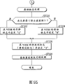
Figure 55 is after explanation reset to finish in the step of Figure 54, the flow chart of the more new settings that the sign and resetting of filing indicates.
Figure 56 is the flow chart of content of treatment S T318 of the unit playback time of explanation Figure 54.
But Figure 57 is the residue of the dish in the expression video recording become the not figure of demonstration example of for a long time warning demonstration, average record speed and the residue video time under this speed etc.
Figure 58 is the flow chart of another example of playback action of the DVD recorder of explanation Figure 39~Figure 41.
Figure 59 is the flow chart of content of treatment S T710 of the unit playback time of explanation Figure 58.
Figure 60 is the flow chart (1) of one of processing example of the device inediting custom menu of explanation Figure 40 or Figure 41.
Figure 61 is the flow chart (2) of one of processing example of the device inediting custom menu of explanation Figure 40 or Figure 41.
Figure 62 is the flow chart that makes one of the processing example of custom menu file in the device of explanation Figure 40 or Figure 41 automatically.
Figure 63 is the flow chart (1) of one of the processing of retrieval user menu in the device of explanation Figure 40 or Figure 41 example.
Figure 64 is the flow chart (2) of one of the processing of retrieval user menu in the device of explanation Figure 40 or Figure 41 example.
Figure 65 is the flow chart (1) of one of the processing of playback user menu in the device of explanation Figure 40 or Figure 41 example.
Figure 66 is the flow chart (2) of one of the processing of playback user menu in the device of explanation Figure 40 or Figure 41 example.
Figure 67 is the flow chart (3) of one of the processing of playback user menu in the device of explanation Figure 40 or Figure 41 example.
Figure 68 is the figure that selects one of the background picture of custom menu (section menu) and the operation of frame picture example in the device of explanation Figure 40 or Figure 41.
Figure 69 be explanation by with the corresponding picture (figure of one of custom menu of A~E) constitute example that dwindles of video recording content.
Figure 70 be in the specific video recording title (A) of explanation Figure 69 section (corresponding to PGC1~PGC5) with dwindle section menu that the picture constitutes (figure of the relation of A, a1~a4) by it.
Figure 71 is the figure of one of the editing operation of explanation custom menu (section menu) example.
Figure 72 is the figure of one of the expression hierarchy that is included in the information among the object video group VOBS of Fig. 4 example (navigation bag).
The optimal morphology that carries out an invention
Digital information recording playback system according to an embodiment of the invention is described with reference to the accompanying drawings.
As a typical embodiment of digital information recording playback system according to the present invention, have with the device of variable-digit speed record reproducing according to the animation of MPDG-2 coding, for example DVD digital VTR.(object lesson of relevant this DVD digital VTR is hereinafter addressed.)
Fig. 1 is the skeleton view that the structure of the CD-R 10 that is used for above-mentioned DVD digital VTR is described.
As shown in fig. 1, this CD 10 has the structure of a pair of transparency carrier 14 that is respectively equipped with recording layer 17 being fitted by adhesive linkage 20.Each substrate 14 can be made of the thick polycarbonate of 0.6mm, and adhesive linkage 20 can be made of the uv curing resin of extremely thin (for example 40 μ m~70 μ m are thick).The substrate 14 of this a pair of 0.6mm is fitted, recording layer 17 is contacted on the surface of adhesive linkage 20, obtain the thick huge capacity compact discs of 1.2mm 10 whereby.
Center pit 22 is set on CD 10, around the center pit 22 on the two sides of dish, is provided with the pinch zones 24 that clamps usefulness when rotation drives this CD 10.When being placed on CD 10 in the unshowned disk drive device, the main shaft of dish motor inserts in the center pit 22.And CD 10 is clamped by unshowned plate clamp at these pinch zones 24 places in the CD rotation.
Be provided with leading-out zone 26 at its outer circumferential side in the middle of the block of information 25.These external and interior all sides pinch zones 24 adjacency are provided with Lead-In Area 27.And between leading-out zone 26 and Lead-In Area 27, define data recorded area 28.
On the recording layer (reflector layer) 17 of block of information 25, form the record session continuously for example spiral yarn shapedly.This continuous session is divided into a plurality of physical sectors, gives these sectors with serial number.With this sector serves as that the record unit writes down various data on CD 10.
Data recorded area 28 is actual data recorded areas, is writing down voice datas such as auxiliary image data such as video data (main image data), title menu such as film and lines effect sound with same pit row (causing the physical form or the phase transformation state of optic variation in the laser-bounce light) as record reproducing information.
At CD 10 is that each recording layer 17 can be by two-layer zinc sulphide aktivton (ZnSSiO with the occasion of the ram disc of single face one deck two sides record
2) clip phase-change recording material layer (Ge for example
2Sb
2Te
5) three laminations constitute.
At CD 10 is that the recording layer 17 of reading face 19 1 sides can constitute at three interior laminations by comprising above-mentioned phase-change recording material layer with the occasion of the ram disc of single face one deck single face record.In this occasion, be configured in from reading face 19 and see that it is information recording layer that the layer 17 of face-off one side there is no need, can be dead level.
At CD 10 is the occasion of the two-layer RAM/ROM dish of single face reading out type, and two recording layers 17 can (see it is that dark side from reading face 19 by a phase change recording layers; The read-write with) and a semi-transparent metal reflective layer (see side at the moment from reading face 19; Singly put) constitute.
In CD 10 occasion for the DVD-R that writes, can use polycarbonate as substrate, can use ultraviolet curable resin as unshowned diaphragm with golden as unshowned reflectance coating.In this occasion, in recording layer 17, use organic pigment.As this organic pigment, can use cyanine, ス Network ア リ リ ウ system, gram ketone, trityl be pigment, xanthene, benzoquinones be pigment (naphthoquinones, anthraquinone etc.), metal-dislocated be pigment (phthalocyanine, porphyrin, disulfide group toluene wrong fount etc.) etc.
Data to this DVD-R dish write and can carry out with for example semiconductor laser about wavelength 650nm output power 6~12mW.
At CD 10 is the occasion of the two-layer ROM dish of single face reading out type, and two recording layers 17 can constitute with a metallic reflector (seeing it is that dark side from reading face 19) and a semi-transparent metal reflective layer (seeing side at the moment from reading face 19).
In read-only DVD-ROM dish 10, impression forms the pit row on substrate 14 in advance, forms reflection horizon such as metal on the surface of the substrate 14 that has formed these pit row, and this reflection horizon becomes as recording layer 17 uses.On this DVD-ROM dish 10, be not provided as the groove of record session usually especially, but the pit that forms is listed as session performance function on the surface of substrate 14.
In above-mentioned various CDs 10, the ROM information of singly putting as the embossing signal record on recording layer 17.In contrast, on the substrate 14 of the recording layer 17 that has read-write usefulness (perhaps writing usefulness), do not scribe this embossing signal, scribe continuous groove but replace.In this groove, phase change recording layers is set.And then, also be used to the information record at the phase change recording layers of another face portion of groove in the occasion of read-write with DVD-RAM dish.
Moreover, be the occasion of single face reading out type (recording layer is one deck or two-layer) at CD 10, see that from reading face 19 it is transparent with laser that inboard substrate 14 there is no need read-write.This occasion also can be on inboard substrate 14 whole surfaces printed instructions.
The DVD digital VTR of hereinafter addressing can constitute and can coil (perhaps DVD-RW dish) record playback (read-write) repeatedly repeatedly to DVD-RAM, the DVD-R dish is once write down repeatedly reset, and DVD-RAM is reset repeatedly.
In Fig. 1, also represent the data recorded area 28 of CD (DVD-RAM) 10 and the corresponding relation of the record session of record data thereon for example.
At dish 10 is the occasion of DVD-RAM (perhaps DVD-RW), and in order to protect exquisite panel surface, the main body of making dish 10 is housed in the tray salver 11.DVD-RAM dish 10 together inserts the disk drive of the DVD recorder of hereinafter addressing together with tray salver 11, and dish 10 is just pulled out and is clamped at from tray salver 11 on the turntable of unshowned spindle drive motor, and quilt is driven in rotation towards unshowned shaven head.
On the other hand, be the occasion of DVD-R or DVD-ROM at dish 10, the main body of dish 10 is not contained in tray salver 11, but exposed dish 10 is placed directly on the plate rail of disk drive.
Spiral yarn shaped ground forms the data recording session continuously on the recording layer 17 of block of information 25.This continuous session is divided into a plurality of logic sectors (smallest record unit) of certain storage capacity, is that benchmark comes record data with this logic sector.The memory capacity of a logic sector and identical 2048 bytes of hereinafter addressing (or 2k byte) that are defined as of bag data length.
On data recorded area 28, be actual data recording area, similarly writing down management data, master image (video) data, auxiliary image data and/or sound (audio frequency) data.
Moreover, though not shown, coil 10 data recorded area 28 and can annular be divided into a plurality of recording areas (a plurality of posting field) (year wheel shape).Though the angular velocity difference of disc spins for each posting field can be taken as linear velocity or angular velocity constant in each zone.In this occasion, can standby recording areas (free space) be set at each zone.Can be each the free space in this zone gathered the spare area that is used as this dish 10.
Fig. 2 is the figure of one of the hierarchy of the information of declare record on the CD (DVD-RAM or DVD-RW dish) 10 of Fig. 1 example.
Lead-In Area 27 comprises the embossing data field that light reflection surface has the convex-concave shape, and the mirror area of have an even surface (minute surface) and the rewriting of information become possible rewritten district.
Data recording area (volume space) 28 is by being made of volume/file control information 70 and the data field DA that the user rewrites.In the DA of data field, writing down computer data, video data, voice data etc.In volume/file control information 70, writing down the relevant information that is recorded in the All Files or the volume of the audio-visual data among the DA of data field.
Leading-out zone 26 also constitutes can information rewriting.
In the embossing data field of Lead-In Area 27, writing down for example following information in advance:
(1) disc-types such as DVD-ROM, DVD-RAM (or DVD-RW), DVD-R; 12cm, 8cm etc. coil size; Recording density; The information of the relevant whole carriers such as physical sector number of expression start-of-record/end of record (EOR) position;
(2) recording power and recording impulse width; Erase power; Playback power; The information of the relevant record reproducing erasing characteristics such as linear velocity when record is wiped; And
(3) make the information of the manufacturing of relevant each carriers such as numbering.
In addition, the rewritten district of Lead-In Area 27 and leading-out zone 26 comprises respectively for example with inferior segment:
(4) write down the district of the intrinsic dish name of each carrier;
(5) test recording area (in order to confirm the record erased conditions);
(6) district of the management information of the bad block in the relevant data field DA of record.
In the district of above-mentioned (4)~(6), write down and become possible technology by DVD pen recorder (DVD recorder etc.).
Can hybrid recording audio-visual data DA2 and computer data DA1, DA3 in the DA of data field.
Moreover the record order of computer data and audio-visual data and recorded information size etc. are arbitrarily.Logger computer data only in the DA of data field, perhaps only the record audio video data also is possible.
Audio-visual data DA2 comprises control information DA21, object video DA22, picture object DA23 and audio object DA24.
Required control information that control information DA21 comprises and write down (video recording and/or recording), playback, editor, retrieval etc. when respectively handling.
Object video DA22 comprises the information of the content of the video data that is write down.
Picture object DA23 comprises still frame information such as still frame, magic lantern picture.
Audio object DA24 comprises the information of the content of the voice data that is write down.
Moreover the recorded information of the playback object of audio-visual data (content) comprises the object video group VOBS that hereinafter addresses.
Control information DA21 comprises playback control information DA211, record controls information D A212, editor control information DA213 and contract drawing control information DA214.
Playback control information DA211 comprises the required control information of playback time.
Required control information when record controls information D A212 comprises record (video recording and/or recording).
Editor's control information DA213 comprises control information required when editing.
Contract drawing control information DA214 comprises about the management information of dwindling picture (sheet contracts) of the retrieval usefulness in the place of wanting to see that video data is interior or editor's usefulness and dwindles image data (corresponding to DA2143).
Contract drawing control information DA214 may comprise fixed pointers DA2141, picture address table DA2142 and dwindle image data DA2143.(relevant fixed pointers DA2141 hereinafter addresses.)
Contract drawing control information DA214 also may and dwindle image data DA2143 institute information of lower layer as picture address table DA2142 and comprise menu index information INFO1, index image information INFO2, magic lantern or still frame information INFO3, information frame information INFO4, bad block information INFO5 and wallpaper picture surface information INFO6.
Fig. 3 is the figure that further specifies the information layered structure of Fig. 2.Here, the formation of representing playback control information DA211 particularly for example.
That is to say that playback control information DA211 has playback admin table PLY_MAT and program chain admin table PGCIT.(details of playback admin table PLY_MAT is hereinafter addressed.)
Program chain admin table PGCIT comprises program chain management information PGC_MAI (details is hereinafter addressed), retrieves program chain retrieval pointer gauge PGC_SRPT and the more than one program chain information PGCI# 1~#n (details is hereinafter addressed) that pointer PGCI_SRP# 1~#n forms by more than one program chain information.Each PGCI retrieval pointer has 4 byte size, represents the beginning address of each program chain information PGCI.
Here, PGC is meant the playback order of order unit, and the unit of resetting in a series of unit is carried out in expression.The playback interval of replay data is represented to specify with its start address and end address in the unit in addition.The playback order of the content of audio-visual data district DA2 is determined by program chain PGC and unit.
Moreover record controls information D A212 has record management table REC_MAT (details is hereinafter addressed).
Fig. 4 is that the unit of object video constitutes corresponding routine figure with program chain PGC in the information layered structure of for example presentation graphs 2.In this information layered structure, the occasion of addressing hereinafter with reference Fig. 5 (occasion of DVD video ROM) is different, does not handle this information unit of video title set VTS.In addition, the function synthesized of video management information VMGI and video title set information VTSI is in control information DA21.
In the information layered structure of Fig. 4, object video DA22 is made of object video group VOBS.This VOBS has and the corresponding content of more than one program chain PGC# 1~#k of using the method designating unit playback order that has nothing in common with each other.
Fig. 5 is the figure of the hierarchy of the information of declare record on the CD (for example DVD-R dish) 10 of Fig. 1.
The data recorded area 28 that forms on the CD 10 of Fig. 1 can have the structure shown in Fig. 5.The logical format of this structure can be determined according to for example ISO 9660 and universal disc format (UDF) bridge as one of standard.
Data recorded area 28 from Lead-In Area 27 to leading-out zone 26 is cut apart as volume space.This volume space 28 may comprise the space (volume/file control information) 70 that volume and the information of file structure are used, and by the space of audio frequency and video application (audio-visual data) usefulness with other application (computer data) but the rewrite data district DA that the space of usefulness is formed.
That is to say that volume space 28 has hierarchy, comprise volume/file control information 70, computer data district DA1, audio-visual data district DA2 and computer data district DA3.The zone of these data fields is distinguished by the border of logic sector.Here, a logic sector is defined as 2048 bytes, and a logical block also is defined as 2048 bytes.Thereby a logic sector is defined as and a logical block equity.Moreover, different with logic sector, adding tediously long information such as error correction information in the physical sector.Therefore the physical sector size is said and logic sector size and inconsistent exactly.
Volume/file control information 70 is equivalent to the directorial area of defined in ISO 9660 and the UDF bridge.According to the description of this information 70, in the system storage (not shown) of the DVD recorder inside that the content stores of following video management program VMG is addressed hereinafter.
In the bottom stratum of audio-visual data district DA2, disposing the control information shown in Fig. 2, object video, picture object and audio object.Control information and object video are corresponding to the file 74A of video management program VMG and comprise more than one video title set VTS# 1~#n 72 at interior file.
In Fig. 5, video management program VMG is made of a plurality of file 74A.In this file 74A, putting down in writing managing video set of titles (72 the information of VTS# 1~#n) (video management information VMGI 75, video management menu with object video group VMGM_VOBS, video management information back-up file VMGI_BUP).
In each video title set VTS 72, storing video data (video packets of hereinafter addressing) by mpeg standard compression, auxiliary image data (the sub-picture bag of hereinafter addressing standard compression or unpressed voice data (audio pack of hereinafter addressing) and sweep length compression in accordance with regulations; Comprise the data bitmaps that a pixel is defined by a plurality of position) and information (the navigation bag of hereinafter addressing used of these data of resetting; Display control information PCI and data serch information DSI).
Moreover, the embodiment that does not use the navigation bag is also arranged, address hereinafter with reference to Figure 72.
Video title set VTS 72 also is made of a plurality of file 74B equally with video management program VMG.This file 74B comprises video title set information VTSI 94, video title set menu with object video group VTSM_VOBS, the video title group heading backup VTSI_BUP with object video group VTSTT_VOBS, video title set information.
Here, (VTS# 1~#n) 72 number is limited to maximum 99 to video title set VTS, and the number that constitutes the file 74B of each video title set VTS 72 in addition is defined as maximum 12.These files 74A and file 74B are distinguished by the border of logic sector equally.
On the control information function of the bottom stratum of audio-visual data district DA2 corresponding to above-mentioned video management information VMGI 75 and video title set information VTSI 94.
Though hereinafter address, the video title group heading is defined as the collection of more than one object video VOB with object video group VTSTT_VOBS.Each VOB is defined as the collection of more than one unit.And program chain PGC is made of the collection of more than one unit.
Be a drama with a PGC for example, a plurality of unit that then constitute this PGC can be construed to corresponding to all scenes in the drama.The content of this PGC (the perhaps content of unit) is determined by for example making the software provider (perhaps comprising device users interior software development person) that is recorded in the content on the dish 10.
Fig. 6 is the figure of the information of declare record in the Lead-In Area 27 of CD 10.Coil 10 1 and be placed in the DVD recorder of hereinafter addressing (perhaps unshowned DVD video machines), just at first read the information of Lead-In Area 27.In this Lead-In Area 27, writing down the reference code and the control data of regulation along the incremental order of sector number.
The reference code of Lead-In Area 27 is made of two error correction code block (ECC piece).Each ECC piece is made of 16 sectors.These two ECC pieces (32 sector) become the additional encryption data and generate.When playback has added the reference code of enciphered data, carry out playback side filter operations that specific data symbol (for example 172) will be reset etc., guarantee data read precision after this.
The control data of Lead-In Area 27 is made of 192 ECC piece.The content of 16 sectors in each piece in 192 duplicate records in the part of this control data.
Fig. 7 illustrates the content of the control data of Lead-In Area 27.This control data that is made of 16 sectors comprises physical format information in an initial sector (2048 byte), comprise dish manufacturing information and content provider's information thereafter.
Fig. 8 illustrates the content of the physical format information of 2048 bytes in the control data that is included in Fig. 7.
On initial byte location " 0 ", putting down in writing any version of recorded information according to dvd standard.
On the 2nd byte location " 1 ", putting down in writing the size (12cm, 8cm etc.) and the minimum read-out speed of recording medium (CD 10).Though the occasion at read-only DVD video has been stipulated 2.52Mbps, 5.04Mbps and 10.08Mbps as minimum read-out speed, also kept other minimum read-out speed.For example by can variable-digit speed the DVD recorder of the experience occasion of recording a video with the average bit rate of 2Mbps, can set minimum read-out speed for 1.5~1.8Mbps by utilizing above-mentioned reserve part.
On the 3rd byte location " 2 ", putting down in writing the dish structure (type of the record number of plies, track pitch, recording layer etc.) of recording medium (CD 10).According to the type of this recording layer, can discern this dish 10 is DVD-ROM or DVD-R or DVD-RAM (perhaps DVD-RW).
On the 4th byte location " 3 ", putting down in writing the recording density (linear density and session density) of recording medium (CD 10).Linear density is represented the record length (0.267 μ m/bit or 0.293 μ m/bit etc.) of each.In addition, session density is represented in abutting connection with session interval (0.74 μ m/ session or 0.80 μ m/ session etc.).On the 4th byte location " 3 ", also be provided with reserve part, so that can specify other numerical value as linear density and the session density of DVD-RAM or DVD-R.
On the 5th byte location " 4~15 ", putting down in writing recording medium (CD 10) data field 28 the beginning sector number and finish sector number etc.
On the 6th byte location " 16 ", putting down in writing packet zone (BCA) descriptor.This BCA is only applicable to the DVD-ROM dish under selecting, be the district of the recorded information after the memory disc manufacture process finishes.
On the 7th byte location " 17~20 ", putting down in writing the spatial capacity of recording medium (CD 10).For example in the occasion of dish 10, coiling the information of putting down in writing expression 2.6GB (perhaps the corresponding sector number of a byte number) therewith on this position of 10 for the DVD-RAM dish of single face one deck record.The occasion of the DVD-RAM that writes down for the two sides at dish 10 is being put down in writing the information of expression 5.2GB (perhaps the corresponding sector number of a byte number) therewith on this position.
The 8th byte location " 21~31 " and the 9th byte location " 32~2047 " are for keeping in the future.
Fig. 9 represents the bibliographic structure of the information (data file) on the CD 10 that is recorded in for example.In the occasion of the hierarchy that adopts Fig. 5, same with the hierarchical file structure of the general-purpose operating system that adopts computing machine, under root directory, connecting the sub-directory of video title set VTS and the sub-directory of audio title group ATS.And, in the sub-directory of video title set VTS, disposing all video files (files such as VMGI, VMGM, VTSI, VTSM, VTS), each file is being managed in perfect orderly.By specifying the path from the root directory to this document, can visit specific file (for example specific VTS).
On the other hand, in the occasion of the hierarchy that adopts Fig. 2~Fig. 4, the video title set VTS of sub-directory is replaced as for example sub-directory of audio-visual data.
And, in the sub-directory of audio-visual data, (1) substituting as video management information VMGI, video title set information VTSI, video management menu data VMGM and video title set menu data VTSM file, storing the file of control information DA21, (2) as the substituting of video data VTS, storing object video DA22, picture object DA23 and audio object DA24.
By specifying the path from the root directory to this document, can visit specific file (for example specific control information).
DVD-RAM shown in Fig. 1 (DVD-RW) dish 10 or DVD-R coil 10 preformats and change into the bibliographic structure with Fig. 9, not use dish (new building) list marketing that can use the dish 10 that this preformatting is crossed as the DVD video record.
For example preformatting the root directory of new building 10 can comprise video title set or the such sub-directory of audio-visual data.This sub-directory can further comprise the menu data file (VMGM, VTSM or contract drawing control information DA214 etc.) that the menu information of store predetermined is used.
Figure 10 illustrates the content with the corresponding catalogue record of bibliographic structure of Fig. 9.
On the 1st relative byte location " 0 ", putting down in writing catalogue record length.
On the 2nd relative byte location " 1 ", putting down in writing the extended attribute record length of cutting apart.
On the 3rd relative byte location " 2 ", putting down in writing the numbering of the initial logic sector of cutting apart on expansion ground.
On the 4th relative byte location " 10 ", putting down in writing the data length of file part.
During day when the information in the expansion that is recorded in the catalogue record put down in writing on the 5th relative byte location " 18 " is recorded.The data of this relative byte location " 18 " can be used for the video program record of video recording during day of (being equivalent to specific VTS or specific audio-visual data) in DVD recorder.
On the 6th relative byte location " 25 ", putting down in writing the file mark of the characteristic of the file of defined in the table 10 of representing ISO 9660.
On the 7th relative byte location " 26 ", putting down in writing the file unit sizes that is divided into file part.
On the 8th relative byte location " 27 ", putting down in writing the interleaving access size at interval that is divided into file part.
On the 9th relative byte location " 28 ", putting down in writing the volume chain store in the volume group in the expansion that is documented in the catalogue record.
On the 10th relative byte location " 32 ", putting down in writing the file ID field length of catalogue record.
On the 11st relative byte location " 33 ", putting down in writing the catalogue of defined among file ID or the ISO 9660.
Putting down in writing the filling field of using as the filling when the file ID field length is even bytes in the back of above-mentioned file ID.
Putting down in writing the management information that system uses in the back of above-mentioned filling field.
That is putting down in writing in the back of above-mentioned information on copyright management whether specific file (for example VTS 01 1.VOB of Fig. 9 or unshowned audio-visual data file) that expression write down be read out once (perhaps whether this document is reset once in the past) reads sign (sign of perhaps resetting).The sign that reads at the file of once also not reading is configured to " 0 " in addition.As long as read once, the sign that reads of this document just is configured to " 1 ".
Put down in writing specific file that expression write down in above-mentioned back of reading sign and whether be and planning the file sign (the perhaps permanent sign of preserving) of permanent content of preserving (perhaps whether be plan to prevent the content that mistake is erased).Even the file sign of the file that also it doesn't matter at erasing is configured to " 0 ".The file sign of the file of planning to preserve all the time and not erasing is configured to " 1 ".
Figure 11 illustrates the object video group VTSTT_VOBS that the comprises Fig. 5 hierarchy in interior information.
As shown in Figure 11, each unit 84 is made of more than one object video unit (VOBU) 85.And each object video unit 85 is as with navigation bag (NV bag) being beginning, the aggregate (packet sequence) of video packets (V bag) 88, sub-picture bag (SP bag) 90 and audio pack (A bag) 91 and constituting.That is to say that the VOBU of object video unit 85 is defined as the collection that wraps all bags that write down 86 tight fronts from certain navigation bag 86 to next one navigation.
These are bundled into to carrying out the least unit when the data transfer process.In addition, the least unit of carrying out processing in logic is a unit of cells, and processing is in logic carried out with this unit of cells.
Above-mentioned navigation bag 86 enrolls among the VOBU of object video unit 85, so that in the middle of the multi-angle image that is made of all camera angle, can both realize not having seam or seam being arranged to the change of any angle.
The playback duration of the above-mentioned VOBU of object video unit 85 is equivalent to by the more than one image sets (group of picture that is included among the VOBU of object video unit 85; Abbreviation GOP) playback duration of the video data that constitutes, this playback duration is determined in 0.4 second~1.2 seconds scope.1GOP is compressed into to be about 0.5 second usually, the picture data of the frame picture about playback 15 width of cloth.
Comprise the occasion of video data at the VOBU of object video unit 85, the GOP (according to mpeg standard) that constitutes by video packets 88, sub-picture bag 90 and the audio pack 91 formation video data stream of lining up.But the number of a GOP is irrelevant therewith, is that benchmark is determined the VOBU of object video unit 85 with the playback duration of GOP, arranging navigation all the time in its beginning concerning the embodiment of Figure 11 and wrapping 86.
Moreover in the replay data that audio frequency and/or auxiliary image data are only arranged, be that a unit constitutes replay data also with the VOBU of object video unit 85.For example, serving as beginning only is made of the VOBU of object video unit 85 audio pack 91 occasion with navigation bag 86, same with the occasion of the VOB of object video unit 83 of video data, the audio pack 91 that will reset in the playback duration of the VOBU of object video unit 85 that this voice data belongs to is stored among the VOBU of this object video unit 85.
, can be in interior video title set VTS is recorded in DVD recorder on the CD 10, is created in and plans the situation of reference record content after the record of this VTS the VOBS 82 that comprises the structure shown in Figure 11.In order to answer this requirement, just in each VOBU 85, can insert empty bag 89 as one sees fit.This empty bag 89 can write down middle utilize such as occasion of editor with data afterwards.
As shown in Figure 11, object video group (VTSTT_VOBS) 82 is defined by the set of more than one object video (VOB) 83.Object video VOB 83 among the object video group VOBS 82 is used for same purposes.
The VOBS 82 that menu is used is made of a VOB 83 usually, is wherein storing a plurality of menu screens demonstration data.In contrast, the VOBS 82 that uses of set of titles is made of a plurality of VOB 83 usually.
Here, be example if record a video with certain rock band's concert, then can think to constitute set of titles is equivalent to the performance of this band with the VOB 83 of object video group VTSTT_VOBS 82 view data.In this occasion, by specifying VOB 83 concert playing music purpose the 3rd song for example of this band of can resetting.
In addition, storing the concert of this band and play the complete bent menu data of song in constituting the VOB 83 of menu with object video group VTSM_VOBS, along with the demonstration of this menu, the specific song of can resetting for example requires the performance song of drilling again.
Moreover, in common video program, can constitute a VOBS 82 by a VOB 83.In this occasion, a video flowing finishes with a VOBS 83.
On the other hand, in the film of the cartoon collection of for example a plurality of plots or short-movie collection of choice specimens form, can in a VOBS 82, a plurality of video flowings (a plurality of program chain PGC) be set corresponding to each plot.In this occasion, each video flowing is stored among the corresponding VOBS 83.At this moment, audio stream and the sub-picture stream that is associated with each video flowing also finishes in each VOB 83.
On VOB 83, can additional identification number (IDN#i; I=0~i), an identiflication number is specified this VOB 83 thus.VOB 83 is made of one or more unit 84.Though common video flowing is made of a plurality of unit, the video flowing that menu is used also is made of a unit 84 sometimes.On each unit 84, adding identiflication number (C_IDN#j) equally with the occasion of VOB 83.
Moreover the information among the object video group VOBS of Fig. 4 of being included in becomes removing 86 demodulation of navigation bag from the hierarchy of Figure 11
Figure 12 for example expression reads and carries out the data sequence (packet sequence) of resulting packet form after signal complex demodulation/error correction from CD (DVD-ROM or DVD-RAM) 10 unshowned disk drive.This packet sequence is made of navigation bag (controlling packet) 86, video packets 88, empty bag 89, sub-picture bag 90 and audio pack 91.All these bags are made of the data of 2k byte unit equally with the logic sector of Fig. 1.
Here, so-called above-mentioned angle is switched the angle (camera angle) that means change observation reference object image.With regard to the example of rock band's concert video recording, mean in the performance scene (same incident) of same song, can observe the scene of the outstanding singer of absorption main body, the outstanding scene of taking in the scene of its hand main body of gigabit, the scene of the outstanding drummer of absorption main body etc. from all angles.
As carry out angle switch the example of (or angle change) have can according to the hobby of looking the hearer come the occasion of selected angle and in the process of plot the occasion of Same Scene repeated transformation angle automatically (software development person/supplier constitutes the occasion of plot like this; The user of the DVD recorder of perhaps hereinafter addressing carries out such editor's occasion).
In addition, the occasion as selected angle has following situation.That is to say, have turning back to and discontinuous on the beginning angular transformation time of Same Scene the occasion that angular transformation no seam continuous in time is reset in occasion that seam resets (for example boxer enter camera angle in the scene of moment of counterattack become reset the once more occasion of the scene that counterattack begins to get of another angle) and the scene in then this scene (for example boxer enter counterattack become the reset occasion of the scene that the adversary that strikeed back is knocked down of another angle in the moment camera angle that this boxing enters) arranged continuous in timely.
Moreover the video parcel 882 of Figure 12 comprises unshowned little packet header, is writing down decode time stamp (DST) in this little packet header and is showing time stamp (PTS).In addition, sub-picture parcel 902 and audio frequency parcel 912 comprise unshowned little packet header respectively, are writing down demonstration time stamp (PTS) in these little packet headers.
In addition, be recorded in the packet sequence that is comprised among the object video group VOBS on DVD-RAM or the DVD-RW CD 10 and can constitute the navigation bag 86 that does not comprise Figure 12.The structure example of the packet sequence when not comprising the navigation bag is shown in Figure 72.
Figure 13 illustrates another example (but removing navigation bag 86 in the occasion of the structure that applies to Fig. 2~Fig. 4) of content of orlop bag of the hierarchy of Figure 11.
In the bag of Figure 13 constitutes, be provided with two kinds of video packets.That is to say, as video packets prepared to comprise master image bag (MPEG-2 video) interior V1 bag 88A and comprise retrieval with picture bag etc. at interior V2 bag 88B.In V1 bag 88A, distributing stream ID=0xe0.Distributing stream ID=0xe1 among this external V2 bag 88B.
Figure 14 illustrates the structure of the bag of void bag of Figure 12.That is to say, the void bag 89 of a bag by packet header 891, have regulation stream ID parcel title 892 and constitute with the padding data 893 that the code of regulation embeds.(parcel title 892 and padding data 893 constitute filling parcel 890.) use the content of the empty padding data 893 that wraps nonsensical.
After these empty bag 89 video recordings that can on the dish 10 of having finished Fig. 1, stipulate, when this video recording content of editor, suitably utilize.In addition, storage be used for custom menu Fig. 2 dwindle image data (the sheet data contract) DA2143 the time also can be with empty bag 89.
For example, consider the video-tape of family's travelling being recorded a video with field camera coils an occasion from video editing on 10 to DVD-RAM (perhaps DVD-RW).
In this occasion, at first only record a video selectively on the dish 10 planning to be pooled to a video scene on the dish.This video scene is recorded in the video packets 88 (the perhaps V1 of Figure 13 bag 88A) of Figure 11.In addition, the SoundRec of recording simultaneously with video camera is in audio pack 91.
In addition, the menu that shows each section that is pooled to a video scene on the dish can take the circumstances into consideration to be recorded among the V2 bag 88B of Figure 13 with dwindling image data.
In the occasion of the data structure that adopts Fig. 5, comprising this video packets 88 has navigation bag 86 (occasion of Fig. 2~Fig. 4 do not navigate bag) at interior VOBU85 in its beginning.As shown in Figure 12, this navigation bag 86 can comprise playback control information PCI and data serch information DSI.Utilize this PCI or DSI can control the playback step (for example can automatically couple together the scene of disperseing, write down many scenes) of each VOBU.
From video-tape after dish 10 editor video recordings,, can be recorded in after-recording sound or BGM in the empty bag 89 in occasion of each scene middle and later periods recording sound effect sound etc. or the occasion of appending background music GBM by VOBS unit.In addition, in the occasion of the explanation of appending the video recording content, also can be recorded in sub-pictures such as the literal that appends, figure in the empty bag 89.And then, can insert video record to this in void bag 89 in the occasion of planning to insert the video recording image that appends.
Above-mentioned after-recording sound etc. writes the padding data 893 as the void bag 89 of audio pack.Above-mentioned in addition explanation of appending etc. writes the padding data 893 as the void bag 89 of sub-picture bag.Same above-mentioned insertion video recording writes the padding data 893 as the void bag 89 of video packets.
That is to say that empty bag 89 can become audio pack or sub-picture bag or video packets according to application target, is the bag as the asterisk wildcard.
Figure 15 illustrates the content of the video management program VMG of Fig. 5.This VMG is made of a plurality of file 74A.This video management program VMG is adapted to each file and comprises the backup (VMGI_BUP) with group of objects (VMGM_VOBS), video management information of video management information (VMGI) 75, video management menu.
Here the backup VMGI_BUP of video management information VMGI and video management information can be taken as necessary project, and the object video group VMGM_VOBS that expression video management info menu VMGM uses can be taken as selectable items.
As shown in Figure 15, be configured in the video management information (VMGI) 75 of beginning of video management program VMG video management information management table (VMGI_MAT; Must), title retrieval pointer gauge (TT_SRPT; Must), the table (VMGM_PGCI_UT of program chain information unit of video management menu; When VMGM_VOBS exists must), origin management information table (PTL_MAIT; Optional), video title set attribute list (VTS_ATRT; Must), text data supervisory routine (TXTDT_MG; Optional), video management menu cell address table (VMGM_C_ADT; Necessary when VMGM_VOBS exists) and video management menu object video unit address table (VMGM_VOBU_ADMAP; When VMGM_VOBS exists must) by this one the order put down in writing.
Moreover, the start address addresses such as (TT_SRPT_SA) of the end addresses (VMGI_MAT_EA) of video management information management table VMGI_MAT or title retrieval pointer TT_SRPT, the relative logical block number that the logical block of being stored by this Table V MGI_MAT is from the outset counted is put down in writing.
Video management information (VMGI) 75 comprises 72 o'clock used information of each video title set (VTS) of playback Fig. 5, and the border of these information and logic sector as one man is recorded on the CD 10.
Storing menu information (video management program VMG management) in object video group VMGM_VOBS at the video management info menu about being recorded in video data, voice data and auxiliary image data on the CD 10.
A video management info menu can show the file label of the CD that will reset, the sound of following the file label demonstration and the explanation of sub-picture with object video group (VMGM_VOBS) thus, and can show the project that can select with sub-picture.
For example, with object video group (VMGM_VOBS), can show that the CD that after this will reset comprises the situation of certain boxer X of storage up to the video recording (with the form of single current or multithread) of the match that obtains the world champion by the video management info menu with sub-picture.That is to say that the termination fight of file label such as the glorious history of boxer X and boxer X is reset by video data, and his theme song (if any) is by voice output, and then shows his historical chronology etc. that sees action by sub-picture.
In addition, as the option that shows with sub-picture with object video group (VMGM_VOBS) by VMGM, for example export the explanation sound that any language such as inquire in English (1), Japanese, French, German are reset and competed with menu-style, and whether (2) show the captions of prescribed language in sub-picture, and any of the multilingual captions that can select selected in (3) inquiry.According to the demonstration of this VMGM with object video group (VMGM_VOBS), to look hearer (user of the DVD recorder of hereinafter addressing) and for example can select that sound is English, the sub-picture captions are Japanese.So, the video recording of the match of appreciation boxer X is ready.
Utilize any selection of explanation, voice language or subtitle language of the recorded content of above-mentioned such sub-picture and/or sound, though perhaps the such feature of the change of aforementioned replay angle is unexistent in the video recorder (VHS type VCR etc.) of prior art, adopts the DVD recorder of the data structure of Fig. 5 can have these features.
A part of also representing the content of video management information management table VMGI_MAT among Figure 15 for example.That is to say, in this video management information management table VMGI_MAT, putting down in writing spatial capacity (recordable capacity) FREE_SPACE of CD 10, whether have the custom menu of custom menu to have sign in the expression CD 10, and other various information.
Moreover, among the classification VMG_CAT of the video management program in being included in video management information management table VMGI_MAT (not shown), putting down in writing the video copy sign and the audio frequency copy sign of video management program and video title set here.Individually determine respectively that according to the content of these signs can video and sound copy.
The spatial capacity of Figure 15 (recordable capacity) FREE_SPACE, the spatial capacity data in the physical format information of untapped blank panel 10 and Fig. 8 are identical.In the storage means of dish 10 spatial capacity, consider to the storage of filec descriptor part (physical format information) with to the storage of management information part (VMGI_MAT etc.).Partly video recording has used the capacity of circling or whirl in the air after this dish 10 can write the spatial capacity part (be taken as the both sides that write FREE_SPACE and physical format information here) of the physical format information of the FREE_SPACE of Figure 15 and/or Fig. 8.
For example, on the byte location 17~20 of Fig. 8, write the information of expression 2.6GB in the occasion of the single face DVD-RAM of capacity 2.6 GB dish 10.If on this dish 10 is the state of not recording a video fully, then in the FREE_SPACE of Figure 15, write the information with some amounts such as the storage that from 2.6GB, deducts management data (also comprising video management program VMG).
If carried out for example video recording of 1GB amount on this dish 10, though then the information of the byte location 17~20 of Fig. 8 is equivalent to 2.6GB, the information rewriting of the FREE_SPACE of Figure 15 becomes to be equivalent to the content of about 1.6GB.If the dish 10 that this part was recorded a video is placed in the DVD recorder of hereinafter addressing, then this DVD recorder read at first Fig. 8 byte location 17~20 information and to detect the dish of being placed 10 are dishes of 2.6GB, then read Figure 15 FREE_SPACE information and to detect the dish of being placed 10 be that spatial capacity is the dish of 1.6GB.If this dish 10 is erased fully, then the information of the spatial capacity of the physical format information of the FREE_SPACE of Figure 15 and Fig. 8 part all is rewritten into and is equivalent to 2.6GB.
That is to say that even represent same " spatial capacity ", the spatial capacity of Fig. 8 and the FREE_SPACE of Figure 15 also may be different in terms of content.
Figure 16 is the figure that the title of explanation Figure 15 is retrieved the content of pointer gauge TT_SRPT.Writing down title retrieval pointer information TT_SRPTI, title playback form TT_PB_TY, angle among this title retrieval pointer gauge TT_SPRT and counting part (section) number PTT_Ns, this source id field, the video title group # VTSN of AGLNs, title, video title retrieval pointer gauge VTS_TTN, video title set start address VTS_SA, user's title menu exist sign, main PGC to number and display position information such as (X, Y).
In this title, there is occasion user's title menu existence of user's title menu to be masked as " 01 ", exists at the occasion user's title menu that does not have user's title menu to be masked as " 00 ".
Writing the PGC that dwindles picture that typically has that is utilized in the access customer title menu in main PGC numbering numbers.
In display position (X, Y), write the X-Y coordinate that dwindles picture in the access customer title menu picture.
Figure 17 illustrates the content of the video title set VTS 72 of Fig. 5.The video management program VMG of this video title set VTS and Figure 15 is made of a plurality of file 74B equally.Each file 74B comprise video title set information (VTSI) 94, video title set menu with group of objects (VTSM_VOBS), video title group heading with object video group (VTSTT_VOBS; Maximum 9 files) and the backup (VTSI_BUP) of video title set information.
As shown in Figure 17, be configured among the video title set information VTSI 194 of beginning of video title set VTS 72 video title set information management table (VTSI_MAT; Must), the title of part (for example section of the program) usefulness of the title of video title set retrieves pointer gauge (VTS_PTT_SRPT; Must), the program chain information table (VTS_PGCIT of video title set; Must), the table (VTSM_PGCI_UT of program chain information unit that uses of video title set menu; When VTSM_VOBS exists must), video title set time chart (VTS_TMAPT; Optional), the element address table (VTSM_C_ADT that uses of video title set menu; When VTSM_VOBS exists must), the object video unit address figure (VTSM_VOBU_ADMAP that uses of video title set menu; When VTSM_VOBS exists must), video title set element address table (VTS_C_ADT; Must) and the object video unit address figure (VTS_VOBU_ADMAP that uses of video title set; Must) put down in writing by this order.
A part of in Figure 17, also representing the content of video title set information management table VTSI_MAT for example.That is to say, in this video title set information management table VTSI_MAT, putting down in writing expression be recorded in program on the CD 10 whether reset fully playback once cross sign (PLAY_END sign), plan reservation record on CD 10 program and the occasion of not erasing is brought into play file sign (ARCHIVE sign) and other the various information that prevent to miss the function of erasing.
Moreover, each information project of above-mentioned Table V TSM_MAT, consistent with the border of logical block of data on being recorded in CD 10.
Figure 18 is the figure of content of the playback admin table PLY_MAT of key diagram 3.In this playback admin table PLY_MAT, writing down the identifier ID of playback management object data, the start address VOBS_SA of object video group, the end address VOBS_EA of object video group, the end address CTLI_EA of control information, the end address PLYCI_EA of playback control information, the classification CAT of playback management object data, the attribute V_ATR of video, audio frequency fluxion ST_Ns, the attribute AST_ATRT of audio stream, sub-picture fluxion SPST_Ns, the attribute SPST_ATRT of sub-picture stream, there is sign in custom menu, main PGC numbering, display position (X, Y), and the sign etc. of resetting.
In the playback management data, there is the occasion custom menu existence of custom menu to be masked as " 01 ", exists at the occasion custom menu that does not have custom menu to be masked as " 00 ".
What write in the custom menu in main PGC numbering to be utilized has a PGC numbering of typically dwindling picture.
In display position (X, Y), write the X-Y coordinate that dwindles picture in the custom menu picture.
In the occasion of once also not resetting after the playback management object data recording is being reset sign, write " 0 ", in this sign of occasion of once all resetting once, write " 1 ".
Figure 19 is the figure of content of the record management table REC_MAT of key diagram 3.In this record management table REC_MAT, putting down in writing end address REC_MAT_EA, spatial capacity FREE_SPACE and the sign etc. that files of end address RECI_EA, the record management table REC_MAT of record controls information.
But being written in the user in spatial capacity FREE_SPACE has carried out the record of various data or has erased coiling remaining recording capacity in 10 afterwards.
In addition, be recorded in and plan in the middle of the data of dish on 10 to write " 1 " in the file sign of permanent data of preserving.Even write " 0 " in the file sign of the whole data that also it doesn't matter of erasing later on.
Figure 20 is the figure of content of the PGC management information PGC_MAI of key diagram 3.End address PGCI_TABLE_EA, the end address PGC_MAI_EA of program chain management information, the start address PGC_SRP_SA of program chain retrieval pointer, end address PGC_SRP_EA, the start address PGCI_SA of program chain information, the end address PGCI_EA of program chain information and the total PGC_Ns of program chain of program chain retrieval pointer that in this PGC_MAI, comprise program chain information table PGCIT.
Program chain retrieval pointer PGC_SRP is the beginning of pointing to each program chain information PGCI, by can easily carry out the retrieval of each PGCI with this pointer.
Figure 21 is the figure of content of the PGC information PGCI of key diagram 3.This PGC information PGCI comprises the program chain program figure PGC_PGMAP and the more than one cell playback CELL_PLY_INF# 1~#m of the inlet number of program chain general information PGC_GI, expression program.
Figure 22 is the figure of content of the PGC general information PGC_GI of explanation Figure 21.This PGC general information PGC_GI comprises the content PGC_CNT of program chain, the playback duration PGC_PB_TM of program chain, the audio stream control table PGC_AST_CTLT of program chain, the sub-picture Flow Control tabulation PGC_SPST_CTLT of program chain, the Navigation Control PGC_NV_CTL of program chain, the palette table PGC_SP_PTL of sub-picture, the start address PGC_PGMAP_SA of the program figure of program chain, the start address CELL_PLY_SA of cell playback, use unit number CELL_Ns in the object program chain, there is sign in the menu data of program chain, display position (X, Y), the sign of resetting, and the sign etc. that files.
In the object program chain, there is the occasion PGC menu data existence of menu data to be masked as " 01 ", exists at the occasion PGC menu data that does not have menu data to be masked as " 00 ".
In display position (X, Y), write the X-Y coordinate in the demonstration of PGC menu data.
In the occasion of once also not resetting behind the object program chain record is being reset sign, write " 0 ", in this sign of occasion of once all resetting once, write " 1 ".
In addition, filing and writing " 1 " in the sign planning the occasion of permanent conservation object program chain, though erase afterwards that also it doesn't matter occasion in the sign that files, write " 0 ".
Figure 23 is the figure of content of the cell playback CELL_PLY_INF of explanation Figure 21.This cell playback CELL_PLY_INF comprises unit classification C_CAT, unit playback duration C_PBTM, the sign of resetting, sign, unit start address CELL_SA and end address, unit CELL_EA etc. file.In unit start address CELL_SA, write the start address in the interval of resetting, in the CELL_EA of end address, unit, write this interval end address as the unit.
In the occasion of once also not resetting behind the object unit record is being reset sign, write " 0 ", in this sign of occasion of once all resetting once, write " 1 ".
The occasion of the permanent conservation object of this external plan unit writes " 1 " in the sign that files, though erase afterwards that also it doesn't matter occasion in the sign that files, write " 0 ".
Moreover said units classification C_CAT and unit playback duration C_PBTM utilize as unit general information (CELL_GI).
Figure 24 illustrates the content of the video title set program chain information table VTSI_PGCIT of Figure 17.
In this video title set program chain information table VTS_PGCIT, comprise video title set program chain information table information (VTS_PGCITI), video title set program chain information retrieval pointer (VTS_PGCI_SRP# 1~VTS_PGCI_SRP#n) and video title set program chain information (VTS_PGCI).
Moreover the order that is provided with a plurality of video title set program chain information VTS_PGCI is set with the sequence independence ground of a plurality of video title set program chain information retrieval pointer VTS_PGCI_SRP# 1~VTS_PGCI_SRP#n.Thereby, for example indicate same program chain information VTS_PGCI to become possibility by more than one program chain information retrieval pointer VTS_PGCI_SRP.
The content of in Figure 24, representing video title set program chain information VTS_PGCI for example.That is to say that program chain information (PGCI) is by program chain general information (PGC_GI; Must), program chain command list (PGC_CMDT; Optional), program chain program figure (PGC_PGMAP; When next C_PBIT exists must), cell playback table (C_PBIT; Optional) and unit location information table (C_POSIT; When aforementioned C_PBIT exists must) constitute.
The content of in Figure 24, also further representing cell playback table C_PBIT for example.This cell playback table C_PBIT has illustrated formation, comprises maximum 255 cell playback (C_PBIn; #n=#1~#255).
The cell playback C_PBI of Figure 24 (C_PBI# 1~#n) comprise respectively, though not shown, the end address (C_LVOBU_EA) of the end address (C_FILVU_EA) of the initial staggered unit (ILVU) in the start address (C_FVOBU_SA) of the initial object video unit (VOBU) in unit classification (C_CAT), unit playback duration (C_PBTM), the unit, the unit, the start address (C_LVOBU_SA) of the final video object unit (VOBU) in the unit and the final video object unit (VOBU) in the unit.
Though not shown, said units classification C_CAT can comprise following such content.That is to say, this unit classification (C_CAT) can (b0~b7) represents the cell command number with least-significant byte, (b8~b15) represents the unit residence time with 8 that follow, (b16~b20) represents cell type (for example Karaoke) with 5 that follow, represent the restrict access sign with 1 (b21) following, represent unit manner of playback (for example animation or still frame) with 1 (b22) following, skip the reservation position and represent not have seam angle change sign, represent the discontinuous sign (whether the STC zero clearing) of system clock pulse STC with 1 (b25) then with 1 (b24) then, with 1 (b26) following represent interconnected sign (by the unit of C_PBI appointment be in the continuous blocks or block interleaved in), represent not have seam playback piece with 1 (b27) following (whether the unit by the C_PBI appointment will not have the seam playback), (b28~b29) represents cell block type (for example whether angle block gauge) with 2 that follow, (b30~b31) represents cell block mode (for example whether the initial unit in the piece) with last 2.
Represent not to be the unit in the piece here when the cell block mode is 00b (b is the meaning of scale-of-two), it represents it is initial unit in the piece during for 01b, and it represents it is the unit of piece centre during for 10b, and it represents it is the interior last unit of piece during for 11b.
Represent not to be the part of this piece when the cell block type is for 00b in addition, it represents that this piece is angle block gauge (unit that comprises multi-angle is at interior piece) during for 01b.
When comprising the multi-angle unit this cell block type is not 01b in interior title is reset, can be taken as the state that for example unshowned angle cue mark is lighted.
If in playback, detect this cell block type=01b on the other hand, can notify then that to look the hearer current just in angle block gauge is reset by glittering (perhaps the lighting the change of color, perhaps the change of angle mark shape) of unshowned angle mark.Look the hearer whereby and can know that the picture reproducer about other angles of image in the current playback is possible.
Represent it is that this piece is (a plurality of VOBU continuous recordings) in the continuous blocks during the interconnected in addition 0b of being masked as, represent that this unit is (the ILVU interleaved recorded that comprises more than one VOBU respectively) in the block interleaved during the interconnected 1b of being masked as.
Do not have in addition seam angle change sign set up (=represent that this unit is the object that no seam is reset 1b) time, this sign do not set up (=represent that this unit is the object that the seam playback is arranged 0b) time.
That is to say interconnected sign=1b and become the state that the change of seam angle can be arranged when not having seam angle change sign=0b, interconnected sign=1b and become when not having seam angle change sign=1b and can not have the state that the seam angle changes.
If moreover use (the system of the beginning of the angle block gauge that can want with interior visit in 1 image duration of video of the media drive system that the access time is exceedingly fast; Not necessarily be defined in optical disc drive system), then between interconnected sign=0b set (all angles unit) of the VOBU of noninterlace record just, can realize angle change rapidly.
Be used as the occasion of recording medium at the slow CD 10 of access speed, can distribute to one week of record session of this dish the record of a block interleaved.So, because the tracking target of optical head is just passable along session amount of radial direction fine motion of dish during the transfer (angle change) between the adjacency block interleaved,, the almost not free session that lags behind becomes possibility so shifting (being suitable for not having the change of seam angle).In this occasion, shift the time lag of a circle amount of then maximum generation dish if carry out the session of an object video unit (VOBU) amount.Thereby, follow the angle change of the transfer of VOBU unit to be suitable for not having the change of seam angle.
Here the content of not having seam angle change sign is pre-determined by supplier's (making is recorded in the software development person of the programme content of each title on the CD 10) usually.That is to say that by pre-determining the content of no seam angle change sign, the supplier can determine not have to monodrome the change of seam angle still the change of seam angle.
But can constitute DVD recorder like this, so that after CD has read the cell data of this set of titles, look the content that hearer (user of the DVD recorder of hereinafter addressing) can at random change the no seam angle change sign the reading of data.
Moreover not have seam angle change sign be exactly that the angle information (not shown) that are documented in the navigation bag 86 represent not have the sign that the seam angle still has the seam angle, produces necessity of revising the interior angle information (not shown) of (for example becoming to have the seam angle information from no seam angle information-change) navigation bag 86 when changing this sign.
Be illustrated in when the unit manner of playback is for 0b in addition in the unit continuously and reset, it is illustrated in stop playback among each VOBU that is present in during for 1b the unit in.
This external user carries out the occasion of replay video, and the restrict access sign can use when forbidding the direct selection of being undertaken by user's operation.For example, the restrict access sign by unit that the answer of problem set is write down is taken as 1b, can forbid that the user steals a glance at the answer of problem.
For example be the Karaoke occasion that makes in addition in this unit, cell type can be represented following project by its content of 5.
That is to say, if 00000b designating unit type not then, if 00001b then specifies the title picture of Karaoke, if 00010b then specifies the prelude of Karaoke, if 00011b then specify climax (trill) in addition sing part, if 00100b then specifies the part of singing of the 1st climax, if 00101b then specifies the part of singing of the 2nd climax, if 00110b then specifies the part of singing of male voice, if 00111b then specifies the part of singing of female voice, if 01000b then specifies the part of singing of men and women's mixing sound, if 01001b then specifies intermezzo (the only performance of musical instrument) part, if 01010b then specifies fading in of intermezzo, if 01011b then specifies fading out of intermezzo, if 01100b then specifies the 1st ending to play part, if 01101b then specifies the 2nd ending to play part.The content of remaining 5 code can be used for other purposes.
Moreover angle changes the angle change of the background video recording that also can apply to play Karaoka.(for example can be the singer's who sings guiding sound whole body camera lens, the close-up shot of face, the close-up shot of the corners of the mouth etc., along with the Karaoke music flow process jointlessly, seam ground is arranged when perhaps returning at least forward, and then change by the angle desirably of looking the hearer in the repeat playback between the trifle of wanting.)
Specify when 8 of the unit residence time contents are for 00000000b in addition and do not stop, it specifies the stop in no time limit during for 11111111b, and appointment served as the stop of the length that numerical table shows second with the specified decimal number (1~254) of a content thus when it be 00000001b~11111110b.
The cell command numerical table shows the command number that will carry out when the playback of this unit finishes in addition.
Figure 25 illustrates the content of the program chain general information PGC_GI of Figure 24.As shown in Figure 25, in program chain general information PGC_GI, putting down in writing the content (PGC_CNT) of program chain, the playback duration of program chain (PGC_PB_TM), user's control information operation (PGC_UOP_CTL) of program chain, the control table of program chain audio stream (PGC_AST_CTLT), the control table (PGC_SPST_CTLT) of program chain sub-picture stream, the navigation control information of program chain (PGC_NV_CTL), the sub-picture palette (PGC_SP_PLT) of program chain, the start address of the command list of program chain (PGC_CMDT_SA), the start address (PGC_PGMAP_SA) of the program figure of program chain, the start address (C_PBIT_SA) of the playback information table of the unit in the program chain, the start address (C_POSIT_SA) of the location information table of the unit in the program chain, there is sign in the program chain menu data, and display position (X, Y).
The content PGC_CNT of program chain represents number of programs and the unit number (maximum 255) in this program chain in Figure 25.Number of programs is " 0 " in the program chain that does not have object video VOB.
The playback duration PGC_PB_TM of program chain be with hour, the frame number of minute, second and video represents the total playback duration of the program in this program chain.In this PGC_PB_TM, also putting down in writing the sign (tc_flag) of the type of representing frame of video, coming designated frame speed (per second 25 frames or per second 30 frames) etc. according to the content of this sign.
User's operation of being forbidden in the program chain that user's control information operation PGC_UOP_CTL of program chain represents resetting.
The control table PGC_AST_CTLT of program chain audio stream can comprise 8 audio stream control informations separately.Can these control informations each comprise and be illustrated in the sign (availability sign) that utilize this audio stream in this program chain and from the information converting of audio stream numbering to the audio stream numbering of decoding.
Can the control table PGC_SPST_CTLT of program chain sub-picture stream comprise and be illustrated in the sign (availability sign) that utilize this sub-picture stream in this program chain and from sub-picture stream numbering (32) information converting to the sub-picture stream numbering of decoding.
The navigation control information PGC_NV_CTL of program chain comprises the Next_PGCN of the program chain numbering that will reset after the current program chain of resetting of expression, the program chain that expression is quoted by navigation command " LinkPrevPGC " or " PrevPGC_Search () " is numbered the Previous_PGCN of (PGCN), the GoUP_PGCN of the program chain numbering that expression will be returned from this program chain, the manner of playback of representation program (reset by order, random playback, shift to reset etc.) PG Playback mode, and the Still time value that represents the residence time after the playback of this program chain.
The sub-picture palette PGC_SP_PLT of program chain is putting down in writing employed 16 groups luminance signal and 2 colour difference signals in the sub-picture stream in this program chain.
The start address PGC_CMDT_SA of the command list of program chain is the pre-order, the PGC that carry out before PGC resets post command that the back carries out and the unit record district that cell command that the back carries out uses of resetting of resetting.
The start address PGC_PGMAP_SA of the program figure of program chain uses the relative address of counting from the initial byte of program chain information PGCI to describe the start address of the program figure PGC_PGMAP of the formation of representing the program in this program chain.
The start address C_PBIT_SA of the playback information table of the unit in the program chain uses the relative address of counting from the initial byte of program chain information PGCI to describe the start address of the cell playback table C_PBIT of the playback order of determining the unit in this program chain.
The start address C_POSIT_SA of the location information table of the unit in the program chain is a start address of using the relative address of counting from the initial byte of program chain information PGCI to describe to represent the unit location information table C_POSIT of employed VOB identiflication number and unit identiflication number in this program chain.
Whether there is sign in the PGC menu data is to be described in to have custom menu to use data person in the object program chain.In the object program chain, there is the occasion PGC menu data existence of menu data to be masked as " 01 ", exists at the occasion PGC menu data that does not have menu data to be masked as (00).
Write the X-Y coordinate in the demonstration of PGC menu data in the display position (X, Y).
Moreover the program chain general information PGC_GI of aforementioned Figure 22 can utilize in the DVD recorder of carrying out replay video with the data structure of Fig. 2~Fig. 4 (using DVD-RAM dish or DVD-RW dish person).
The program chain general information PGC_GI of Figure 25 can utilize in the DVD recorder of carrying out replay video with the data structure of Fig. 5 (using DVD-R dish person) on the other hand.
Figure 26 schematically represents one of the occasion of the cell data of playback of recorded on the dish of Fig. 1 example.Replay data is specified to the playback interval of unit F by unit A as shown in FIG..The playback of these unit in each program chain is combined in the program chain information and is defined.
Figure 27 represents the relation of each unit of above-mentioned program chain information and Figure 26 for example.That is to say that this comes designating unit to reset to the PGC# 1 that is made of 3 unit # 1~#3 in proper order by unit A → unit B → unit C.In addition, this comes designating unit to reset to the PGC# 2 that is made of 3 unit # 1~#3 in proper order by cells D → unit E → unit F.And then the PGC# 3 that constitutes with 5 unit # 1~#5 this comes designating unit to reset in proper order by unit E → unit A → cells D → unit B → unit E.
Figure 28 is the figure of the 1st example of the method for the explanation waypoint of determining the video content of video recording on the dish of Fig. 1.Here the waypoint of the sort of indivedual PGC that represent as giving an example among Figure 27 is changed to opportunity in the mode in video recording source.For example, suppose that the video recording source is the television broadcasting of the mixing film of stereosonic Commdity advertisement and monophone (perhaps two countries' language).In the occasion that the movie program of this TV is recorded a video, can voice mode from stereo switch to the point of monophone (perhaps two national languages) or switch to stereosonic waypoint as PGC from monophone (perhaps two national languages) detect automatically.
Figure 29 is the figure of the 2nd example of the method for the explanation waypoint of determining the video content of video recording on the dish of Fig. 1.Here the waypoint as indivedual PGC is an opportunity with the certain video time of process.For example, can irrespectively video time be every through just automatically detecting the waypoint of PGC in 15 minutes with the video recording content.
Figure 30 is the figure of the 3rd example of the method for the explanation waypoint of determining the video content of video recording on the dish of Fig. 1.Here the waypoint of the indivedual PGC of conduct is input as opportunity with user's mark key.If for example the user is while seeing that the content of recording a video recognizing that moment that scene changes carries out the mark key input then all determine the waypoint of PGC at every turn.
Figure 31 is the figure of the 4th example of the method for the explanation waypoint of determining the video content of video recording on the dish of Fig. 1.For example pause in video recording waypoint that operation just can be used as PGC of each user detects automatically and pauses constantly in the video recording operation of the digital camera of DVD-RW dish.The waypoint that the operation that pauses even perhaps reset in the playback of the DVD-RW dish of recording a video behind the video recording at every turn just can be used as PGC detects the moment of pausing automatically.
Figure 32 is the figure of the 5th example of the method for the explanation waypoint of determining the video content of video recording on the dish of Fig. 1.To pitch-black frame (or field), occasion perhaps jumpy on the contrary detects this rapid variation to the content of for example recording a video in the short time about 1/15 second~1/3 second from snow-white frame (or field).And the waypoint that can be used as PGC detects this check point automatically.
At the picture that dwindles of the custom menu of the content that is used for recording a video, consider motion picture and still frame picture.Though the occasion at motion picture is no problem for common MPEG video format, the occasion of still frame picture just after the I picture insertion sequence end code adapt to.
Figure 33~Figure 35 illustrates several examples of video recording structure of the video packets of the part of still frame playback in the middle of the video content on the dish of Fig. 1.Figure 33~Figure 35 also represents all insertion forms of said sequence end code for example.
In the example of Figure 33, append order end code " 000001B7 " at the end of I picture and comprise custom menu with still frame in interior I picture packing.
In the example of Figure 34, after the interior little packetize of I picture, appending the only parcel of order end code " 000001B7 " with still frame comprising custom menu.
In the example of Figure 35, after interior I picture packing, appending the only parcel of order end code " 000001B7 " with still frame comprising custom menu.Moreover, only append in the method for parcel of order end code, in this bag, append suitable filling parcel, being adjusted to a bag must become 2048 bytes.
The form of custom menu file can be taken as the formation shown in Figure 36 in principle, can be taken as the formation shown in Figure 37~Figure 38 on concrete.
The order of data that at first enters the custom menu file is as among Figure 36 from top to bottom for example the expression, by point of fixity, dwindle pictures management portion, dwindle the backup (not shown) of pictures management portion, the order of dwindling image data group, point of fixity is put down in writing.
In entering the pointer address that is called point of fixity (a, p, b, q among Figure 36) of this custom menu file at first, putting down in writing the start address (a) and end address (p) that dwindle pictures management portion respectively, is start address (b) and end address (q) that dwindles the Backup Data of pictures management portion then.
Writing down the pictures management portion that dwindles in the back of point of fixity, the processing of " adjustment of 32 k bytes " that this data acceptance is hereinafter addressed.One dwindle the data of respectively dwindling picture that writing down relevant formation custom menu in the pictures management portion at this.
Data as the reality of dwindling picture of relevant formation custom menu, PGC numbering, time code (can be used for time retrieval etc.) are arranged, dwindle picture the beginning address, use sector number (=data length), dwindle picture size, point to the source file (AV data) that dwindles picture address (pointer), be used to retrieve or the text of title etc.
If the back has the occasion of bad block writing down the beginning address and the data length of this bad block in file again.And accession designation number and beginning address etc. thereof about the background frame data recording of custom menu.
Though the back is not shown again, writing down the backup of dwindling pictures management portion.This backup is in order to write down at the aforementioned insurance of dwindling the damage in pictures management district.
What the reality of having packed was being write down in the back again dwindles the image data group.But these data pin are dwindled picture to each and have been adjusted by the 32k byte.
The point of fixity identical with the beginning of custom menu file (a, p, b, q) put down in writing in the back again.So, just considered the situation that file begins to damage from the directorial area of visiting many beginnings usually.By file point of fixity also is set at last, improve security more.
Carried out the adjustment of 32k byte in each segmentation of this external this file and be because can visit by the ECC group of 32k byte unit when considering change, append or erasing in data.Visit more at a high speed becomes possibility whereby, has alleviated the load in the action of data processing 36 of Figure 39~Figure 41 that hereinafter addresses.
Moreover the address information in this custom menu file all uses the relative address of counting from the beginning of file to represent.
In the custom menu file of Figure 36, following feature is arranged:
(1) menu at still frame place of representing the part of video data is at least selected to write down more than one in same custom menu file with image data (just dwindling image data).
(2) pictures management of dwindling portion is arranged, be recorded in the management that on the recording medium (DVD-RAM dish, DVD-RW dish or DVD-R dish) all are dwindled the image data appointment of place of retention video signal corresponding (with) blanketly.
In the custom menu file of Figure 36, specifically write the content of representing for example among Figure 37 and Figure 38.
That is to say, putting down in writing the starting position of picture address table, the end position of picture address table, the starting position of reservation picture address table and the end position of reservation picture address table as the 1st fixed pointers that the picture address table is used; Putting down in writing menu index information (INFO1), index image information (INFO2), bad block information (INFO5), wallpaper picture surface information (INFO6) and padding data as picture address table (corresponding to the DA2142 of Fig. 2); Putting down in writing the starting position of picture address table, the end position of picture address table, the starting position of reservation picture address table and the end position of reservation picture address table as the 2nd fixed pointers that the picture address table is used.
Moreover in the picture address table of Figure 37 and Figure 38, also take the circumstances into consideration putting down in writing magic lantern and still frame information INFO3 and the information frame information INFO4 of Fig. 2.
The menu index information of Figure 37 comprises index frame numbers, information frame number, magic lantern and still frame number, bad block number and wallpaper frame numbers.
The index image information content characteristic of Figure 37, index picture are with the address and the retrieval text data of the use sector number of the starting position of the time code of the ID of program chain, index picture, index picture, index picture record, picture dimension, original audio-visual data.
Moreover be included in the content character in the index image information, write down then be recited as " 1 " if be used for the still frame of custom menu, if only write down the record position (address) of this picture then be recited as " 0 ".
Only come the designated user menu to comprise the address of the ID of the program chain PGC that the content character, magic lantern and the still frame that are recited as " 0 " use, original audio-visual data and the time code of magic lantern and still frame as shown in Figure 38 with the index image information of the occasion of picture with the address.
The wallpaper picture surface information of Figure 38 comprises the wallpaper frame numbers (numbering of the background picture of registration) that can be used as the background picture of custom menu, the starting position of wallpaper picture and the use sector number in the district that the wallpaper picture writes down.
The padding data of Figure 38 comprises the content of index picture, the content of bad block and the content of wallpaper picture etc.
Describe with regard to aforesaid " adjustment of 32k byte " below.
In the custom menu file shown in Figure 36~Figure 38, with recording areas and not the situation of recording areas irrespectively all cut apart the position on definite in advance " ECC border " as its boundary member by 32 k bytes as the unit (ECC group) of error correction code.
In the occasion that record respectively dwindles image data, point of fixity, dwindles pictures management portion and dwindle the backup of pictures management portion, it is consistent with above-mentioned " ECC border " position that the record start position of all data becomes with the end of record (EOR) location records.
Than how many littler occasions of round values of 32k byte additional as shown in Figure 36 " empty district ", make the end of record (EOR) position consistent in each data volume with " ECC border " position.This one " empty district " means " filling " district of Figure 37.
Carrying out recording of information by aforesaid " ECC border " when the record that dwindles picture is erased erases.In this occasion, owing to there is no need to change the information of the part in the ECC group, directly repeat to write and dwindle data so when record, can contrast the ECC border.
If carry out above this " adjustment of 32k byte ", then because dwindle image data and additional error correction information no longer needs to revise, so realize the high speed that the record of ECC group unit is erased and handled in order to write down with ECC group unit to erase.
The custom menu file of Figure 36 has been considered the transplantability to other recording mediums of utilizing personal computer etc.Therefore, custom menu is used dwindles picture, background picture, dwindle the preservation address in pictures management district, all uses the difference address of counting from the beginning address of custom menu file (relative address) to express.
Dwindling in the contingency table in the pictures management district of Figure 36, illustrate from PGC and number the corresponding tables of retrieval with one group of two row of text data.
In corresponding the understand fully relation of dwindling image data and vision signal that write down of this occasion according to the group of the time code of vision signal and beginning address.
In addition by retrieve whole this contingency table understand fully the not recording areas in the custom menu file or erase after dwindle the position of erasing of image data, can be recorded in this district to the new image data that dwindles.
In the custom menu file of Figure 36, be taken as comprise audio-visual data on interior AV file the position and dwindle the management of carrying out bad block in the contingency table between the picture record position.
Concrete disposal route when just causing that attached to the dish lip-deep dust of (recording medium) 10 or damage dwindling pictures management portion damages here describes.
The at first damage of dwindling pictures management portion that causes of the dust on detection dish (recording medium) surface or damage.(whether whether damaging can be failed by the error correction of ECC group is judged.)
Detect the occasion of damage, reading the information of point of fixity, calling the Backup Data address that dwindles pictures management portion, reading in the Backup Data that dwindles pictures management portion.
Secondly seek not recording areas in the custom menu file according to the contingency table between the picture record position of dwindling of Figure 36.Be recorded in not recording areas in the custom menu file dwindling the pictures management data then, upgrade the address information of point of fixity.
Then cause as the dust on bad block registration dish (recording medium) surface or damage and dwindle the place that pictures management portion damages dwindling in the contingency table between the picture record position of Figure 36.
If adopt the custom menu file layout of Figure 36~Figure 38, then can expect following effect:
(a) realize dwindling appending retrieval and visiting high speed of image data by aforementioned " adjustment of 32k byte ".
(b) show once that on the display part of unshowned monitor display several dwindle the occasion of picture, be necessary to dwindle the image data position at respectively dwindling on the picture access recording medium this.One dwindle image data and scatter (dispersions) occasion on recording medium at this, visit needs the time, and several dwindle the disadvantage that required time that picture uses is spun out to exist demonstration.If but like that a plurality of image datas that dwindle being collected in the same custom menu file and are configured of expression for example in the image pattern 36, this custom menu file of then only resetting just can show at high speed that several dwindle picture.
(c) all of dwindling in the pictures management portion by blanket management are dwindled image data, and the management of erasing or appending processing of dwindling image data has become easily.The retrieval that is to say not recording areas in the custom menu file (perhaps dwindle image data erase district) has become easily, carries out new the appending of image data of dwindling at high speed and registers as possibility.
(d) in the DVD recorder of addressing hereinafter, per 16 bags (=32k byte) gather as the additional error correction information of ECC group and are recorded on the dish (DVD-RAM, DVD-RW or DVD-R) 10 in data processor 36.If thereby during the information of the part in the change ECC group, the correction of the error correction information of add necessitates, handle becoming numerous and diverse and the information-change processing will be spent a lot of times.But, aforementioned by carrying out " adjustment of 32k byte " with ECC group unit write down the correction of dwindling the error correction information of being added when the image data of erasing become unwanted, the record of high speed processing custom menu data and erase and become possibility.
(e), can guarantee point of fixity and the high reliability of dwindling pictures management portion, dwindling the Backup Data of pictures management portion by following method:
*Guarantee to dwindle the reliability in pictures management district
The backup area in pictures management district is dwindled in setting, for just in case dwindle the pictures management district damage get ready and can be when being damaged the moving recording place;
*Guarantee to represent to dwindle the reliability of point of fixity information in the record place in pictures management district
Constitute the ECC piece separately, reduce the data change number of times and be recorded in two places (the 1st and the 2nd point of fixity of Figure 36);
*Damage management processing
The dust or the damage that are taken as on dish (recording medium) surface cause from the information playback that dwindles pictures management portion or point of fixity impossible occasion that becomes, and can read data again from aforesaid backup portion, record other position again.Whereby, can prevent wrong registration bad block and reuse this bad block.
Moreover overlap its former picture at title or the multilayer literal that image data seals sometimes that dwindle that is used for custom menu.In such occasion, also can constitute after the literal multilayer and dwindle picture.In addition, also considered only to constitute to dwindle picture with this lteral data.
And then can not have the actual image data that dwindles yet, only come the explicit user menu with dwindling picture (on one side dwindling occasion that picture show in order in demoder, to make on one side in the formation of Figure 40 that adaptation is addressed hereinafter) at hardware one side formation custom menu with the pointer that points to former picture.If use this method, though then because frequently coiling retrieval when menu shows will spend the some time so custom menu shows, the dish capacity that obtains using can reduce the advantage of in fact not dwindling the amount of picture.
Figure 39 for example expression with variable recording rate with the information of the structure that illustrates among Fig. 2~Figure 25 formation at the device (DVD recorder) of the disc recording playback digital cartoon information of Fig. 1.
Taking it by and large the apparatus main body of the DVD recorder shown in Figure 39 drives DVD-RAM (DVD-RW) dish 10 or DVD-R dish 10 by rotation, this dish 10 is carried out the dish drive division (32,34 etc.) of the read-write of information, constitute the encoding section 50 of video recording side, constitute the lsb decoder 60 of playback side, and the microcomputer piece 30 of the action of control device main body constitutes.
In ADC 52, input is from the external analog video signal+external analog sound signal of AV input part 42, perhaps from the anolog TV signals+analoging sound signal of television tuner 44.This ADC 52 with 8 of sample frequency 13.5MHz for example, quantization digit the analog video signal digitizing of being imported (so-called 4: 4: 4 occasion among the MPEG).(in this occasion, briliancy composition Y, aberration composition Cr (perhaps Y-R) and aberration composition Cb (perhaps Y-B) quantize with 8 respectively.)
Perhaps, come digitizing (so-called 4: 2: 2 occasion among the MPEG) with sample frequency 6.75MHz, 8 of quantization digits respectively at aberration composition Cr (perhaps Y-R) and aberration composition Cb (perhaps Y-B) the analog video signal of being imported-come digitizing with sample frequency 13.5MHz, 8 of quantization digits at briliancy composition Y.
Moreover ADC 52 passes through digital audio and video signals when analog video signal and digital audio and video signals are input to ADC 52.(also can not change the content of digital audio and video signals, only reduce the processing of the shake of following digital signal, perhaps change the processing of sampling rate or quantization digit etc.).
Digital video signal composition from ADC 52 is delivered to formatter 56 via video encoder (V scrambler) 53.Deliver to formatter 56 from the digital audio and video signals composition of ADC 52 via audio coder (A scrambler) 54 in addition.
The V scrambler has the function that the digital video signal of being imported is converted to the digital signal of having compressed with variable-digit speed according to MPEG-2 or Moving Picture Experts Group-1.
In addition, A scrambler 54 has the function that the digital audio and video signals of being imported is converted to the digital signal of having compressed with fixed bit speed (the perhaps digital signal of linear PCM) according to MPEG or AC-3 standard.
Constitute (the occasion of video recording on the DVD-RAM/DVD-RW bag that do not navigate in the data shown in Figure 11~Figure 13 or Figure 72; The occasion of video recording on DVD-R has navigation bag) the DVD vision signal from the occasion of AV input part input, the sub-picture signal content (sub-picture bag) in the occasion DVD vision signal that the DVD vision signal broadcasting that perhaps this data constitute is received by television tuner 44 respectively can take out from the DVD video machines that the sub-picture scrambler for example have an independent output terminal of sub-picture signal.The auxiliary image data of input SP scrambler 55 is organized into the signal aspect of regulation and delivers to formatter 56.
Here explanation makes the encoding process content of the standard that above-mentioned record data use simply.That is to say that encoding process at the beginning in the encoding section 50 of Figure 39 is just set parameter required in the coding of video (master image) data and voice data (with reference to the step ST20 of the Figure 49 that hereinafter addresses).Then, utilize the parameter that sets that main image data is carried out precoding, calculate the distribution of optimal symbol amount in the average transfer rate (recording rate) that sets.According to like this in precoding resulting symbol weight distribute the coding of carrying out master image.This moment, the coding of voice data was also carried out simultaneously.
Result in precoding, the occasion of data compression quantity not sufficient (the desired video program can not deposit the occasion that DVD-RAM coils or DVD-R coils that will record a video fully in), the precoding once more if having an opportunity (if for example the video recording source is the source that video-tape or optic disk etc. can be reset repeatedly), then carry out the coding again of the part of main image data, Bian Ma part main image data is replaced by the main image data part of precoding before this again.By this a series of processing, main image data and voice data are encoded, and the value that writes down required average bit rate reduces significantly.
The same setting the auxiliary image data required parameter of encoding makes the auxiliary image data of having encoded.
Main image data, voice data and the auxiliary image data of having encoded as above combine, and are transformed into the data structure of video recording usefulness.
That is to say that tailor-made is the unit of the least unit of main image data (video data), makes the cell playback (C_PBI) shown in the cell playback shown in Figure 23 (CELL_PLY_INF) or Figure 24.Then, (the resulting information when part of these attribute informations is utilized to each digital coding) such as attributes of formation, master image, sub-picture and the audio frequency of the unit of the program chain shown in setting pie graph 4 or Fig. 5, make and comprise all information at interior information management table information (VMGI_MAT of Figure 15 or the VTSI_MAT of Figure 17, the perhaps PLY_MAT of Figure 18).
Main image data, voice data and the auxiliary image data of having encoded is subdivided into the bag of certain size (2048 bytes or 2k byte).In these bags, take the circumstances into consideration to insert empty bag (Figure 14).Moreover in the bag beyond the void bag, take the circumstances into consideration to put down in writing PTS (demonstration time stamp), DTS (decode time stamp) equal time stamp.Can put down in writing the time that the PTS than the main image data of same playback duration band or voice data postpones arbitrarily about the PTS of sub-picture.
And in VOBU 85 units, can in proper order dispose each data cell by the time code of each data with resetting, constitute the VOB 83 that constitutes by a plurality of unit shown in Figure 72.The VOBS 82 (the not occasion of navigation bag) that gathers more than one this VOB 83 is formatted into the structure of Fig. 2~Fig. 4.Perhaps, the VOBS 82 (image pattern 11 has the occasion of navigation bag like that) that gathers more than one this VOB 83 is formatted into the structure of Fig. 5.
Moreover in the occasion from DVD video machines digital copies DVD replay signal, because contents such as said units, program chain, admin table, time stamp have been determined the necessity that makes so do not revise them at the very start.(but can constitute the DVD recorder system in digital copies DVD replay signal ground for wanting, preferably be particular about the employing in electronics gap, the employing of the serial copy management SCMS of system is to the additional literary property royalty of new building and other copyright protection measures.)
The dish drive divisions that DVD dish 10 is carried out the read-write (video recording and/or reset) of information have the dish portion 100 that changes, disk drive 32, interim storage part 34, data processor 36 and system time counter (perhaps system clock pulse; STC) 38.
Interim storage part 34 is used for buffer memory and writes a certain amount of in the middle of the data (from the data of encoding section 50 outputs) of dish 10 via disk drive 32, perhaps buffer memory via disk drive 32 from coiling a certain amount of in the middle of 10 data of resetting (data of input lsb decoder 60).
For example interim storage part 34 can be with the recording rate buffer memory of average 4Mbps about 8~16 seconds record or replay data when constituting by the semiconductor memory (DRAM) of 4M~8M byte.Interim in addition storage part 34 can be with the recording rate buffer memory of average 4Mbps about 32 seconds record or replay data when constituting by the EEPROM (flash memories) of 16M byte.And then interim storage part 34 can be with about record or the replay data more than 3 minutes of the recording rate buffer memory of average 4Mbps when constituting by the microminiature HDD (hard disk) of 100M byte.
Interim storage part 34 coils 10 occasions that run low midway in video recording and can be used for interim storage and change the video information of new building up to dish 10 into.
Interim in addition storage part 34 can also be used to storing within a certain period of time the data of reading more than common driver with high-speed driver (2 times more than the speed) as the occasion of disk drive 32 temporarily.If the reading of data of playback time buffer memory in interim storage part 34, even when then causing unshowned optical sensor read error, can not have the interruption of reproduced picture by switching the replay data of using buffer memory in interim storage part 34 by vibratory impulse etc. yet.
Though but if not shown among Figure 39 outside draw-in groove is set on DVD recorder, then above-mentioned EEPROM can be used as optional IC-card list and sells.If outside draw-in groove or scsi interface are set on DVD recorder in addition, then above-mentioned HDD also can be used as optional extended driver list and sells.
Moreover, among the embodiment of the Figure 48 that addresses hereinafter (personal computer being treated as the DVD recorder person of using) with software, can be the interim storage part 34 of the part of the part of the dead zone of the hard disk drive of personal computer itself or primary memory as Figure 39.
The data processor 36 of Figure 39, defer to the control of microcomputer piece 30, DVD record data from encoding section 50 are supplied to disk drive 32, take out from coiling the 10 DVD replay signal of resetting from driver 32, rewriting is recorded in the management information (VTSI_MAT of the catalogue record of Figure 10, the VMGI_MAT of Figure 15, Figure 17, the PLY_MAT of Figure 18 etc.) of dish on 10, perhaps is recorded in erasing of data on the dish 10.
The MPU of this microcomputer piece 30 defers to the program that is stored among its ROM, its RAM as the workspace, is carried out the spatial capacity of hereinafter addressing and detects (the step ST12 of Figure 49 etc.), record amount (video recording bag number) and detect and (detect (the step ST420A of Figure 51 etc.), warning (with reference to Figure 57), recording mode change indication and other processing (Figure 49~56 or Figure 58~Figure 67) with reference to Figure 44~Figure 47), surplus.
Will notify the user's of DVD recorder content (Figure 57 or Figure 68~Figure 71 etc.) on the display part 48 of DVD recorder, to show in the middle of the execution result of MPU 30, perhaps in monitor display (Figure 57) with screen on display (OSD) show.
Moreover MPU 30 control time of changing dish portion 100, disk drive 32, data processor 36, encoding section 50 and/or lsb decoder 60 distribute can according to carry out from the time data of STC 38 (though the action of replay video usually with synchronously carry out from the time clock of STC 38, processing in addition also can by concerning STC 38 independently the time distribute carry out).
Lsb decoder 60 has from the DVD replay data with the pack arrangement shown in Figure 11~Figure 13 or Figure 72 and separates the separation vessel 62 that takes out each bag, the storer 63 that bag uses when separating with other signal Processing execution, to the main image data (video packets 88 of being separated by separation vessel 62, the content of 88A or 88B) Video Decoder of decoding (V demoder) 64, the sub-picture demoder (SP demoder) 65 that the auxiliary image data (content of sub-picture bag 90) that is separated by separation vessel 62 is decoded, the audio decoder (A demoder) 68 that the voice data (content of audio pack 91) that is separated by separation vessel 62 is decoded, taking the circumstances into consideration to synthesize in video data from V demoder 64 from the auxiliary image data of SP demoder 65, menu, outstanding button, sub-pictures such as captions are overlapped in master image and the video processor 66 exported, the video dac (VDAC) 67 that converts analog video signal from the digital video output of video processor 66 to, and the audio digital to analog converter (ADAC) 69 that converts simulated audio signal from the DAB output of A demoder 68 to.
Supply to unshowned external component (the multichannel sterego device+monitor tv machine or the projector of 2 sound channels~6 sound channels) from the analog video signal of ADAC 67 with from the simulated audio signal of ADAC 69 via AV efferent 46.
Be input to the separation vessel 62 of lsb decoder 60 from the osd data of MPU 30 output, be input to video processor 66 by V demoder 64 (not carrying out decoding processing especially).So this osd data is overlapped in master image, supply to the external monitor televisor that is connected in AV efferent 46.So for example the warning literal shown in Figure 57 shows with master image.
Figure 40 be explanation with among variable recording rate the disc recording playback digital cartoon information person (DVD recorder) with the hum pattern 1 of Fig. 2~structure illustrated in fig. 4, have the block scheme of one of the device example of the function that makes custom menu.
Omit repeat specification with common label with the common part of Figure 39 below, describe with the center of constituting intrinsic among Figure 40.
At first data processor 36 can directly be visited jumbo interim storage part 34.
Lsb decoder 60 comprises the intensive circuit block that forms 600 of function of separation vessel 62, V demoder 64, SP demoder 65 and the A demoder 68 of Figure 39, the video data that processing is decoded by circuit block 600 and the video processor 66 of auxiliary image data, the audio frequency DAC and the DAB output interface 69 that the voice data (numeral) of being decoded by circuit block 600 are carried out analog-converted and output.
The device of Figure 40 also has vision mixer (V mixer) 602 in the decoding side, frame memory 604, video DAC and digital video output interface 67 that the video data (numeral) that the custom menu data are taken the circumstances into consideration to mix by V mixer 602 carries out analog-converted and output.
Though details is addressed hereinafter, MPU 30 gives encoding section 50 the coding setting data, receives the segment information (with reference to the explanation of Figure 28~Figure 32) of PGC from encoding section 50.MPU 30 receives the image data that dwindles that is utilized the custom menus from V mixer 602 in addition, the text data from the custom menu to V mixer 602, the movement directive that menu shows and the background picture that gives custom menu as required that give to show in.The text data of delivering to V mixer 602 from MPU30 can be from key input part 49 inputs.This text data is as search key.
Data processing in the device of Figure 40 can be divided into video record processing and reset and handle two kinds.
In video record processing, MPU 30 1 receives the video recording order (the record button connection of telepilot etc.) from the user, just reads in management data from disk drive 32, determines the write area of the dish 10 in being placed on driver.Then, set directorial area, in disk drive 32, set the start address that writes of video data, carry out the preparation of record data so that write the write area that sets.
Then 30 couples of STC of MPU 38 carry out the zero clearing of timer.Here STC 38 is timers of system, is that benchmark carries out replay video with this timer value.During this external this timer zero clearing, also carry out the description of PGC and set.
For example just carry out the occasion that PGC demarcates at regular intervals, MPU 30 sets this description for 15 minutes as shown in Figure 29 interval time.The switching signal (switching signals of perhaps stereo/two national languages) of this external stereo/monophone by sound signal carry out PGC when demarcating 30 pairs of encoding section of MPU 50 carry out these settings.And then MPU 30 carries out other required various settings.
The flow process of the vision signal for when video recording shown in Figure 40.
At first changed by A/D and carry out digitizing by the external AV signals of television tuner 44 or AV input 42 inputs.Digitizing picture signal be input to V scrambler 53 and dwindle video encoder 58.Digitizing voice signal be input to A scrambler 54.By television tuner 44, text signals such as the header signal of sealing or text broadcast are input to SP scrambler 55 in addition.
And then the mode of the source data of PGC description usefulness changes signal (stereo/monophonic signal, aspect ratio pictures change signal etc.) and is input to encoding section 50 from television tuner 44.
Each scrambler (53~55) compresses and little packetize the signal of being imported separately (video, audio frequency, sub-picture).(but each parcel is that 2048 bytes are by description and little packetize in when packing by a bag.) these signals of having compressed are input to formatter 56.Here formatter 56 is as required according to demonstration time stamp PTS that determines each parcel from the timer value of STC 38 and decoding time stamp DTS and write down it.
But the parcel that dwindles picture that is utilized in the custom menu is sent to and dwindles the storer 59 that picture-storage is used, and is kept at the there temporarily.Finishing the back about these parcel data of dwindling picture in video recording is recorded as another file.The size of dwindling picture in the custom menu can be chosen to for example about 144 pixels * 96 pixels.
Though moreover can use the MPEG-2 compression identical as the compressed format of dwindling picture in the formation of Figure 40 with master image, also can be other compress modes.The losing lustre that needs 256 looks), compression modes such as tiff format, PICT form for example can utilize JPEG compression, sweep length compression (palette 256 looks:.
This moment, formatter 56 was delivered to MPU30 to the description address of PGC as PGC description information.
Moreover the interim storage part 34A of conduct is because of the record data that keep with high speed access more than a few minutes, so be envisioned for mass storage or high speed HDD etc.
When being through with video recording according to the data structure of Fig. 2~Fig. 4, MPU 30 makes and writes down PGC information table PGCIT (with reference to Figure 20~Figure 21) according to the PGC description address information that receives from encoding section 50 just now among playback control information DA211 (with reference to Fig. 3).
But MPU 30 is for reading and writing of files directorial area etc. and can be via the bus access data processor 36 of MPU.By this visit, the read-write of the session impact damper in 30 pairs of data processors of MPU 36 becomes possibility.
In addition, also considered custom menu with the data of dwindling picture, and inserted during record data put as another video packet data not as another file.Though that is to say as shown in Figure 13 in the DVD video format stream numbering to be specified to (stream ID:0E0 h) No. 0 as master image, so dwindle picture with in stream numbered be specified to (flowing ID:0E1 h) No. 1, it also is possible carrying out multilayer.Like this multilayer the dwindling picture and become menu editing and handle of stream numbering " 1 " time employed source data.
This is external to make the occasion of dwindling another file that picture uses, another file that this file uses when becoming the custom menu file of using after making.Employed source file when this another file also can be taken as the custom menu editing and processing.
And then encode by dwindling video encoder 58 as the source data of dwindling picture with the initial frame data of PGC according to description information in the occasion that automatically makes the custom menu file, be stored in storer 59.And after the title of custom menu file makes when end of record (EOR), the parcel data group that is stored in the storer 59 is recorded on the dish 10.
The data processing of playback time is as follows in the formation of Figure 40.
At first operate one according to the user and receive the playback initiation command, MPU 30 just reads in dish 10 directorial area via data processor 36 from disk drive 32, determines the address of resetting.
Then MPU 30 delivers to disk drive 32 to the address and the read command of the replay data of determining just now.
Above-mentioned each parcel data when it transmits beginning showing the time stamp PTS STC38 that packs into.The value of each demoder in the circuit block 600 and the PTC in the parcel data synchronously (compares the value of PTC and STC on one side) processing of resetting on one side then, just can show the animation that has the sound captions on unshowned monitor tv machine.
This external explicit user menu is used when dwindling picture, and the picture that dwindles that is kept at just now in another file is flowed as the stream bag with file, specifies display position (X, Y coordinate) and show in frame memory 604.If having this moment such as the occasion of text data etc., use character ROM (perhaps Chinese character ROM) etc. text display below dwindling picture.
Figure 41 be explanation with variable recording rate with the information of Fig. 2~structure illustrated in fig. 4 in the enterprising line item playback of the dish of Fig. 1 digital cartoon information person (DVD recorder), have the block scheme of another example of the device of the function that makes custom menu.
Omit repeat specification with common label with the common part of Figure 39 or Figure 40 below, describe with the center of constituting intrinsic among Figure 41.
The formation of Figure 41 comprise the interim storage part 34B of high capacity, vision mixer 602, frame memory (divide text with and video with 2 pictures) 604 etc.Though video DAC/ interface 67 and the audio frequency DAC/ interface 69 of Figure 40 are not shown, also can use the formation of Figure 41.
Be provided with in the encoding section 50 of Figure 41 external AV input 42 or from the digitized ADC 52 of the analog video simulated audio signal of television tuner 44, selection is from the digital video signal of ADC 52 or from the dwindling image data and deliver to the selector switch 53S of video encoder 53 of vision mixer 602, memory buffer 57 as the workspace and formatter 56 from the various packing data of video encoder 53, audio coder 54 and sub-picture scrambler 55.
Be provided with the separation vessel 62 that the playback bag that sends from data processor 36 is separated into master image, sub-picture and sound in addition in the lsb decoder 60 of Figure 41, audio frequency that is separated by separation vessel 62 and sub-picture are expanded the audio frequency sub-picture demoder 65/68 of (decoding) with the method for regulation, with the method for regulation the Video Decoder 64 of the master image expansion (decoding) that is separated by separation vessel 62, and carry out the video flowing of having decoded dwindle demonstration usefulness processing dwindle picture generating unit 64A.
Processing when recording a video in the formation of Figure 41 is as follows.
At first MPU 30 1 receives the video recording order, just reads in management data from disk drive 32, determines write area on unshowned dish 10.Then set directorial area so that write determined district, on disk drive 32, set the start address that writes of video data, carry out the preparation of record data.
Then MPU 30 is the time zero clearing of STC 38.Here STC 38 is timers of system, is that benchmark carries out replay video with this timer value.Also carrying out the description of program chain PGC this moment sets.
Here as the condition of demarcating has the occasion (Figure 29) of just demarcating at regular intervals, the violent scene of variation of the occasion (Figure 28) of demarcating with the switching signal of the stereo/monophone of sound signal, the occasion of demarcating with the switching signal of the aspect ratio of figure sheet mode 16: 9 and 4: 3, the image data distinguished when encoding is demarcated occasion (Figure 32) etc.
The flow process of vision signal is as follows in the formation of Figure 41.
At first in order to carry out the coding of master image, the selector switch 53S in the encoding section 50 switches to and selects master image one side.
Then be sent to V scrambler 53 from the digital video signal that television tuner 44 or the AV input 42 external AV signals of being imported have carried out the A/D conversion via selector switch 53S by 52 couples of ADC.The digital audio and video signals that has been carried out the A/D conversion by ADC 52 is sent to A scrambler 54.Its text signal is sent to SP scrambler 55 when comprising text subtile information (literal of the title of sealing, the broadcasting of literal multilayer etc.) from the broadcasting of television tuner 44.
And then used stereo/monophonic signal (perhaps stereo/two national language signals) is input to encoding section 50 from television tuner 44 in the PGC description.
Above-mentioned each scrambler (53~55) compression signal and little packetize separately.(but each parcel is that 2048 bytes are by description and little packetize in when packing by a bag.) little packetize signal separately be input to formatter 56.Here formatter 56 is determined the demonstration time stamp PTS and the decoding time stamp DTS of each parcel and is write down it according to the timer count value of STC 38 as required.
The data processor 36 of Figure 41 ties together per 16 bags (=32k byte) as ECC to be organized and additional error correction information, delivers to disk drive 32.But still unripe to coiling 10 occasions that write down at disk drive 32, the data of having added the ECC group of error correction information are sent to interim storage part 34B, wait by the time till dish 10 enterprising line items ready.In the ready stage of record, disk drive 32 begins the record to coiling 10 then.
Here the interim storage part 34B of conduct is because of the record data that keep under high speed access more than a few minutes, so the imagination mass storage.
When finishing video recording according to the data structure of Fig. 2~Fig. 4, MPU 30 makes PGC information table PGCIT (with reference to Figure 20~Figure 21) and write down it according to the PGC description address information that receives just now in playback control information DA211 (with reference to Fig. 3).
Moreover MPU 30 can be for directorial area of reading and writing of files etc. and via the bus access data processor 36 of MPU.
The data processing of playback time is as follows in the formation of Figure 41.
At first one receive user's reproduction command, MPU 30 just reads in directorial area via data processor 36 from disk drive 32, determines the address of resetting.Then MPU 30 is sent to disk drive 32 to the address and the read command thereof of determined replay data just now.
In the inside of demoder 60, separation vessel 62 receives the bag data of being read and carry out parcelization.And according to the purpose of data, video parcel data (MPEG video data) transmit to V demoder 64, and audio frequency parcel data/sub-picture parcel data transmit to A/SP demoder 65/68.
Above-mentioned each parcel data that transmits when transmitting beginning showing the time stamp PTS STC 38 that packs into.The value of PTS in each demoder (64,65/68) and the parcel data synchronously (compares the value of PTS and STC on one side) processing of resetting on one side then.Can on unshowned monitor tv machine, reset whereby and have the animation of sound captions.
This is external make that custom menu uses dwindle picture the time, 30 pairs of V demoders 64 of MPU send and dwindle display command (dwindling ' connection ' order), and vision mixer 602 is specified display positions.Whereby can be on unshowned monitor tv machine the explicit user menu with dwindling picture.If the data of selecting the user to preserve, then this dwindles image data and transmits to V scrambler 53 from V mixer 602 via selector switch 53S.Transmitted dwindle image data in V scrambler 53 by little packetize, packaged in formatter 56, via data processor 36 be recorded in the dish 10 on.
Moreover the explicit user menu serves as that the stream bag flows with the picture file that dwindles that is kept in another file when dwindling picture on unshowned TV monitor etc., and frame memory 604 is specified display positions and shown.At this moment, if the occasion of text data etc. is being arranged, use Chinese character ROM etc. text display below dwindling picture.
Figure 42 illustrates one of the outward appearance of apparatus main body 200 of DVD recorder of Figure 39~Figure 41 and front panel thereof example.
One pushes the opening/closing button 5g of the telepilot of addressing hereinafter with reference to Figure 43 5, and the plate rail inlet 202 of Figure 42 is just to opening at the moment.
DVD-RAM that uses in the video recording or DVD-RW dish (dish of the tray salver of packing into) 10 or DVD-R dish (naked dish) 10 are placed on this plate rail.
Then user one pushes the opening/closing button 5g of telepilot 5, and plate rail inlet 202 is just closed, and the dish (for example DVD-RW dish) 10 that is placed on the plate rail is drawn in the disk drive 32 in the apparatus main body 200.So disk drive 32 automatically starts, at first read the physical format information (comprising the spatial capacity data of dish structured data, blank panel etc.) of Fig. 8 by MPU 30.
Then read the control information DA21 (comprising playback control information DA211, contract drawing control information DA214 etc.) of Fig. 2~Fig. 4 by MPU 30.So, in the display part (liquid crystal or fluorescent display screen) 48 of the DVD recorder of Figure 42, observably show for example project of " DVD-RW " in the occasion of the dish placed 10 for untapped DVD-RW dish (perhaps DVD-RAM dish).In addition video time be shown as 00 (hour): 00 (branch): 00 (second), video recording title/section also is shown as 00-00 (if recorded a video once then this video recording title/section demonstration becomes 00-01).
If device acquiescence or user set in addition, recording mode=MPEG-2, the average bit rate=4Mbps of video recording then observably shows the project of " MPEG-2 " and " 4Mbps " in display part 48.
And then carry out video recording to the dish of being placed 10, if the excess time that can record a video on this dish 10 few (for example after 5 minutes), then MPU 30 detects this situation (for example the ST422A ' of Figure 51 is '), observably shows the project of urging " this changes and has coiled " of changing dish in display part 48.
Also be provided with skip Button, rewind down key, fast forward button, video recording start button (not shown) and other basic operation keys of power switch button, opening/closing key, playback key, stop key, section/program on the front panel of DVD recorder main body 200.
Moreover the DVD recorder of Figure 42 imagination is not the occasion of changing dish portion 100 (changing dish portion 100 is connected in the apparatus main body 200 of Figure 42 by scsi cable etc. as optional external device (ED) occasion) of interior dress Figure 39.In the video recording of this occasion, be placed on dish 10 in the apparatus main body run low before above-mentioned " this changes and has coiled " beginning of display part 48 luminous or glittering.Coiling 10 residual capacity one then becomes zero, and video recording just automatically continues the DVD-RW dish 10 more than that is placed in the outside dish portion that changes 100.
Perhaps prepare the DVD recorder more than two, the usefulness telecommunication cable connects MPU 30 daisy chain separately, and it also is possible using the relaying video recording of the DVD recorder more than two.Also can " carry out the video recording of 1 hour MPEG-2/ average bit rate 4Mbps with the 1st video recorder, carry out the video recording of 2 hours MPEG-2/ average bit rate 2Mbps " in this occasion with the 2nd video recorder.
Carry out the occasion of relaying video recording in many DVD recorder of above-mentioned this usefulness, " carrying out the video recording of 1 hour MPEG-2/ average bit rate 4Mbps with video recorder A, carry out the video recording of 2 hours MPEG-2/ average bit rate 2Mbps with video recorder B " such expression also may be displayed on the monitor screen.
Moreover the DVD recorder of Figure 39~Figure 41 constitutes about user's warning or notice are not recorded a video on dish 10.Coil on 10 but be recorded in the video information (average bit rate of video recording, video recording channel number, video recording time etc.) that also can be taken as the downside of the monitor screen that is illustrated in Figure 57 for example several seconds after video recording has just begun.
Figure 43 illustrates one of telepilot 5 example of the DVD recorder of operation Figure 39~Figure 41.Though also can carry out basic operation with the operating key on the front panel that is located at the DVD recorder main body 200 shown in Figure 42, the various operations that produce the feature of DVD are then undertaken by telepilot 5.
Only just be related to below that the actor of feature describes simply in the DVD recorder in the middle of the function (perhaps using method) of each key of the telepilot 5 of Figure 43.
[function of power key (POWER) 5a]
*The primary side of the AC power circuit of connection/shearing device main body.
*When pushing power key under dish is placed on the state of device inside, the kind of differentiation dish (DVD-RW, DVD-R or DVD video recording) also shows it.When being the dish that can't reset, this dish shows this situation.
[function of opening/closing key (OPEN/CLOSE) 5g]
*Open or close plate rail.Push the opening/closing key in the playback if coiling, then device action hereto finishes, and plate rail is opened.The operation of this key 5g of recording a video is invalid.
*If push the opening/closing key under the plate rail open mode, then plate rail is drawn in apparatus main body.Be placed on plate rail on as fruit tray this moment, then reads its management information, shows the kind (DVD-RW, DVD-R or DVD video recording) of the dish of being placed.When being the dish that can't reset, this dish shows this situation.
[function of Menu key (MENU) 5n]
*Be placed on occasion on the plate rail at dish, the root menu in the video title set in the current selection of playback displayed record on dish.Make mistakes in the occasion of holding tray not (or warning) show (OSD).
*The occasion that does not have root menu in the video title set in current selection, make mistakes (or warning) shows.
*Pass through menu operation if in normal playback, push this Menu key after the replayed menus and break away from menu, then begin once more to reset from the preceding position of resetting of menu playback or by the specified position of menu.
*The occasion of pushing in root menu shows turns back to the state before root menu shows.
Moreover at the occasion use custom menu of DVD-RAM video recording (DVD-RW video recording).Though that is to say does not have root menu still to have the occasion of custom menu to use custom menu by the operation of Menu key on the dish.
[function of title key (TITLE) 5p]
*Show title menu in the occasion that dish is placed on the plate rail and disc recording title menu.Make mistakes in the occasion of holding tray not (or warning) show (OSD).
*On the dish on being placed on plate rail not the occasion of record header menu (in perhaps static) in dish is reset can carry out following action.
That is to say if push title key then go up and show title identifier and segment number in the part (for example upper left corner) of picture.If operate title key once more or the state of operating key is not through the stipulated time (for example 3 seconds) thereafter, then title identifier and segment number disappear from picture.
Showing title identifier (for example " 1 ") and segment number (for example " 1 ") on the picture if state under the title identifier (for example " 2 ") wanted of user input, then picture shows becomes " title identifier: 2 " and " segment number: 1 ".If push playback key or placement stipulated time (for example 2 seconds) once more under this state, then the section 1 from title 2 begins to reset.
In the retrieval of this occasion title and section, can make the searched targets title identifier of display part 48 and segment number glittering and notify the user to retrieve.
[function of options button/cursor key (make progress downward warning triangle to) 5q]
*Be used for project choice in the assorted cold dishes list (menu that accesses by title key or Menu key) and the project choice in the setup menu.For example select the occasion of certain project at the warning triangle up or down of pushing above-mentioned options button/cursor key, when this project further comprises several selections branch, select branch can use the warning triangle to the left or to the right of this one options button/cursor key in order to select it.
*The occasion of pushing during certain setting value in audio stream, sub-picture stream or angle shows is if push the upwards warning triangle of this options button then switch to next stream or angle, if push downward warning triangle then switch to stream or angle.
*The occasion of pushing in the title identifier that caused by character generator shows is if push the upwards warning triangle of this options button then switch to next title, if push downward warning triangle then switch to a title.
[function of end key (END) 5end]
*(when breaking away from cycle of treatment) use when the end notification of the processing of the user being selected set is given device.
[function of acknowledgement key (ENTER) 5s]
*Use when confirming item selected in the assorted cold dishes list or in the setup menu.
*Use in the time of also can in menu screen, confirming title identifier and segment number.
[function of return key (RETURN) 5r]
*When the retrieval of carrying out the address on the predefined dish of headline making person, use.Specifically, push during in indication from the disengaging of menu or to the return action of playback starting point.Use when indication turns back to the action of selection bifurcation point of the susceptible joint that the user can select during perhaps also can one in the susceptible joint of resetting.
[function of audio key (AUDIO) 5aud]
*If push audio key in the playback, then (after calling the audio stream information that is embodied on the dish) shows language of audio stream name in (OSD) current playback (when the classification of audio stream is not music etc. but the language) stipulated time (for example 3 seconds) with character generator on the playback picture.If one push audio key again in showing then reset the sound of next audio stream numbering at this.If repeat this audio key operation then the sound (all language) of the audio stream of playback of recorded in this title that circulate successively.
*In the picture of audio stream setting value shows by push aforementioned options button/cursor key 5q can switch to the current audio stream that sets next audio stream or on an audio stream.The content of the audio stream that is switched so reset.
*If push audio key in stopping, then (after calling the audio stream information that is embodied on the dish) shows language name (when the classification of audio stream the is language) stipulated time (for example 3 seconds) that sets in the current selected title on the lan settings picture with character generator.If one push audio key again in showing then set next audio stream numbering at this.If repeat the operation of this audio key then the audio stream sound of cycle sets displayed record in this title successively.
*If in the lan settings picture of audio stream setting value shows, pushed aforementioned options button/cursor key 5q would switch to the current audio stream that sets next audio stream or on an audio stream.
[function of subtitle key (SUBTITLE) 5sbt]
*If push in playback, then (after calling the sub-picture stream information that is embodied on the dish) shows language name (classification of sub-picture stream is the occasion of the language) stipulated time (for example 3 seconds) of (OSD) the current sub-picture stream of resetting on the playback picture with character generator.If one push the subtitle key again in showing then reset the sub-picture of next stream numbering at this.If repeat this subtitle key operation then circulate the sub-picture stream of playback of recorded in this title successively.
*In the picture of sub-picture stream setting value shows by push aforementioned options button/cursor key 5q can switch to the current sub-picture stream that sets next sub-picture stream or on a sub-picture stream.The content of the sub-picture stream that is switched so reset.
*If push the subtitle key in stopping, then (after calling the sub-picture stream information that is embodied on the dish) shows language name (when the classification of sub-picture stream the is language) stipulated time (for example 3 seconds) of the sub-picture stream that sets in the current selected title on the lan settings picture with character generator.If one push the subtitle key again in showing then set next sub-picture stream numbering at this.If repeat this subtitle key operation then the sub-picture streaming voice of cycle sets displayed record in this title successively.
*If in the lan settings picture of sub-picture stream setting value shows, pushed aforementioned options button/cursor key 5q would switch to the current sub-picture stream that sets next sub-picture stream or on a sub-picture stream.
[function of subtitle break-make key (SUBTITLE ON/OFF) 5v]
*Connect the demonstration of cutting off sub-picture (subtitle).
*(sub-picture shows the connection set condition) is if push subtitle break-make key in video playback and in sub-picture shows, then cut off sub-picture stream numbering setting value, show that with character generator (OSD) this setting value stipulated time (for example 3 seconds), afterwards, sub-picture disappeared from picture simultaneously.
*(sub-picture demonstration dissengaged positions) be not if push subtitle break-make key when still showing sub-picture in video playback, then connect sub-picture stream numbering setting value, show this setting value stipulated time (for example 3 seconds) afterwards with character generator simultaneously, the sub-picture (disc recording in the playback the occasion of sub-picture) of the language of the setting stream numbering that playback is connected.
*When in video playback stops, pushing subtitle break-make key, can only carry out the connection cut-out setting that sub-picture shows.
[function of angle key (ANGLE) 5ang]
*At the title of selecting to have the angle block gauge that constitutes by multi-angle information, reset this angle block gauge (angular interval) if the time push, then show angle numbering stipulated time (for example 5 seconds) in (OSD) current playback by character generator.If push the angle key once more in during this angle numbering shows, the synchronization place of then retrieving the unit of next angle numbering also begins to reset therefrom.
If the angle numbering of pushing the angle key again in during above-mentioned angle numbering shows then being write down is switched the playback of the angle after beginning to select successively circularly.
*With character generator picture angles of display numbering the time, the also angle numbering that can directly select to want by the operation of unshowned numerical key (this key input is invalid when numerical key has been imported in the angle block gauge in resetting non-existent angle numbering).Perhaps also can make the increase and decrease of angle numbering by aforementioned options button/cursor key 5q.
*When carrying out the angle switching during still frame is reset in the unit of multi-angle piece, the retrieval constantly of equally also resetting, the still frame of another angle that playback is retrieved.
If the angle numbering of pushing the angle key again in during above-mentioned angle numbering shows then being write down is switched the still frame of the angle after selecting of resetting successively circularly.
[function of display key (DISPLAY) 5u]
*If push this key in stopping or in resetting, then (on the picture of the display part 48 of apparatus main body and/or monitor portion 6) carries out and at that time the corresponding demonstration of various key operation contents.
[function of key (SETUP) 5y is set]
*Be the key that accesses the setup menu of various settings (setting of the setting of the setting of the setting of the setting of picture dimension/aspect ratio, the setting of angle mark, origin locking, the voice language kind of wanting, the subtitle language kind of wanting, the menu language kind of wanting, the setting of the automatic angular way etc.) usefulness of carrying out device, only effective in playback stops.
*One key is set if push this in setup menu shows, then the demonstration of setup menu is cut off, and becomes playback halted state (lan settings picture).
Though the function of the key of above explanation is and the common function of DVD video machines (walkman) that the telepilot 5 that DVD recorder is used also has the key with following function.
[function of video recording mode key 5rmd]
*If in video recording stops or in the video recording pause, push this key, then whenever push once the video recording mode of just switching circularly, promptly MPEG-2/8 Mbps → MPEG-2/6 Mbps → MPEG-2/4 Mbps → MPEG-2/2 Mbps → MPEG-1/2 Mbps → MPEG-1/1 Mbps → automatic picture quality mode → MPEG-2/8 Mbps → ...
If hope is comparable to the quality of the broadcast studio of NTSC,, select MPEG-2/8 Mbps though then video time shortens.Prolong video time a little and when wishing to obtain the above image quality of the standard mode of S-VHS video recording, select MPEG-2/6 Mbps or MPEG-2/4 Mbps.Further prolong video time and when wishing to obtain the above image quality of 3 times of modes of S-VHS video recording, select MPEG-2/2 Mbps.If the image quality of VHS (perhaps CD-Video) degree is just passable usually, then select the words of MPEG-1/2Mbps or MPEG-1/1 Mbps can further prolong video time.
[function of video recording key 5rec]
*On DVD-RW in being placed on the main body of Figure 42 dish (perhaps DVD-R dish) 10 spatial capacity is arranged, and the original start (setting of the difference of MPEG-2/MPEG-1, the average bit rate of record etc.) of video recording usefulness is if push then begin video recording when having finished.
Moreover, do not carry out this original start the user and just push video recording during key, automatically adopt default setting to begin video recording as this original start.
[function of display mode key 5dm]
*, then whenever push once if 10 states that are placed in the main body 200 of Figure 42 are pushed this key down at the DVD-RAM/DVD-RW that can record a video dish (perhaps DVD-R dish), just switch OSD demonstration (the perhaps display part 48 of apparatus main body) by following content:
During day of (1) video recording source (numbering of television channel numbering or AV input)+current;
(2) the average record speed of current set of titles numbering, the time of recording a video, recordable excess time+at that time;
(3) show cut-out
Moreover above-mentioned (1) and (2) also can image pattern 57 in showing like that simultaneously of expression for example.
[function of OSD key 5osd]
*The literal (or picture) that shows usefulness at the MPU 30 of Figure 39~Figure 41 output OSD is if push this key during data, and then the undesirable OSD of user shows that (for example warning literary composition of the screen upside of Figure 57) disappears from monitor screen.If push this key again then osd data that MPU 30 is exported is presented on the monitor screen.
[function of timer key 5tme]
*If push this key then the MPU 30 of Figure 39~Figure 41 outputs to the menu of timer preset (comprising at preserved program specifies video recording to wish the table of channel, recording schedule during day, video recording mode, average record speed etc.) on the screen of unshowned monitor (OSD).Displaying predetermined programme in this menu is set and can be utilized cursor key 5q, acknowledgement key 5s to wait and carry out.
*After the operation of having finished timer preset, if 10 states that are placed in the main body 200 of Figure 42 are pushed the timer key 5tme and the key 5rec that records a video down simultaneously, then the DVD recorder of Figure 39~Figure 41 enters subscription and video recording mode (timer video recording stand-by state) at the DVD-RW that can record a video dish (perhaps DVD-R dish).
[function of menu editing key 5edi]
*If push this key then the MPU 30 of Figure 39~Figure 41 enters the custom menu edit mode of hereinafter addressing (editor addresses hereinafter with reference to Figure 60~Figure 61 about custom menu).
Figure 44 comes the block scheme of detection record in one of recording capacity testing circuit of the recording of information byte number of dish on 10 example (occasion that does not have the transmission clock pulse) by the count recording byte number in the DVD recorder of expression Figure 39~Figure 41.In addition, Figure 45 is the time diagram that distributes time of the counter 31 count recording bytes of explanation Figure 44.
The DVD record data that formatd by formatters 56 in the encoding section 50 of Figure 39~Figure 41 are made of a plurality of packets that form a line (bag is 2048 bytes) 86~91 as shown in Figure 11.
If the MPU of Figure 44 30 indicates the record of above-mentioned DVD record data via the MPU bus, then data processor portion 36 delivers to encoding section 50 (upside of Figure 45) to the request signal RS of the transmission of the data PD that requires above-mentioned packet.Receive that the encoding section 50 (formatter 56) of this request signal RS acknowledges receipt of the answer signal AS (downside of Figure 45) of this request to 36 outputs of data processor portion.Therewith the output of the answer signal AS while, encoding section 50 (formatter 56) transmits the data PD of 1 amount of bytes to data processor portion 36.That is to say that encoding section 50 (formatter 56) is every just exports the answer signal AS of 1 pulse to data processor portion 36 transmission, 1 byte.
This answer signal AS is input to counter 31.Counter 31 is located counting at the rising edge (the percussion point ta of Figure 45) of signal AS and is added 1, keeps counting the content that adds after 1.The content of counter 31 sends back to MPU 30 via the MPU bus.
If deduct above-mentioned record data capacity (count value byte) from coiling 10 spatial capacity (capacity that writes among the FREE_SPACE among FREE_SPACE the VMGI_MAT of Figure 15 or the REC_MAT of Figure 19) in addition, then know the residual capacity (can write down how many bytes after illustrating) of dish 10.And if then this residual capacity divided by the average record bit rate, then know dish excess time (can write down predicted value how long after illustrating) of 10.
Figure 46 comes the block scheme of detection record at another example (occasion that the transmission clock pulse is arranged) of the recording capacity testing circuit of the recording of information byte number of dish on 10 by the count recording byte number in the DVD recorder of expression Figure 39~Figure 41.Figure 47 illustrates that the rolling counters forward of Figure 46 writes down the time diagram of the time distribution of byte in addition.
Figure 46 is whenever bag data PD just transmits example from encoding section 50 output clock pulse signal CK from encoding section 50 to data processor portion 36.
That is to say that then encoding section 50 is sent answer signal AS (the middle side of Figure 47) back to data processor portion 36 if data processor portion 36 delivers to encoding section 50 to request signal (upside of Figure 47) according to the indication from MPU 30.This answer signal AS is not that every transmission 1 byte just takes place, but the gating signal that during the transmission that transmits predetermined byte number, is activated.Deliver to data processor portion 36 from the transmission clock pulse signal CK (downside of Figure 47) of encoding section 50 outputs as the synchronizing signal that byte transmits.
Above-mentioned answer signal AS is added to the 1st input end of ' or ' door 33 as gating signal, and above-mentioned transmission clock pulse signal CK is added to the 2nd input end of this one ' or ' door 33.So ' or ' door 33 is located counting and is added 1 whenever the rising edge (a plurality of percussion point tb of Figure 47) of transmission clock pulse signal CK during answer signal AS activates (logical zero), keeps counting the content that adds after 1.The content of counter 31 sends back to MPU30 via the MPU bus.
Figure 48 is the block scheme of occasion of the record reproducing function of the explanation DVD recorder that realizes Figure 39~Figure 41 with general purpose personal computer.Though the personal computer 1000 of Figure 48 can be made of specialized hardware, also can constitute by the general purpose personal computer that generally constitutes.
That is to say and on the internal bus 1002 of personal computer 1000, connecting host CPU 1004, Basic Input or Output System (BIOS) ROM (BIOSROM) 1008, primary memory 1010, video memory 1012, floppy disk (FDD) 1022, keyboard I/O device 1024, Genius mouse I/O device 1026, communication I/O device 1028 etc.High-speed bus via special use on host CPU 1004 is directly connecting cache memory 1006.
On the internal bus 1002 of personal computer 1000, be provided with a plurality of versabus groove (not shown).In these bus ducts, inserting ス カ ジ interface (SCSI plate) 1014, DVD disposable plates 1030, video i/o device (video card) 1032, audio frequency I/O device (audio card) 1034 etc.
On the plate 1014 of SCSI type, connecting SCSI hard disk drive (HDD) 1018 and SCSI type DVD-ROM/DVD-RAM compatible driver 1020 (driver 1020 can also with CD compatibility).
The bitmap display (analog rgb type) 6 that on video card 1032, is connecting high definition, on audio card 1034, connecting the paired loudspeaker of 2 channel stereo 8 (when card 1034 is adorned power amplifier in not, just make and be loaded on loudspeaker 8 in the power amplifier, perhaps between card 1034 and loudspeaker 8, insert unshowned stereo amplifier).
The plate 1030 that the DVD of Figure 48 handles enrolls the hardware suitable with the device 38,50 and 60 of Figure 39~Figure 41.The disk drive 32 of Figure 39~Figure 41 is corresponding to the DVD-ROM/RAM driver 1020 of Figure 48.
As required can be the storer 63 of the part of the memory block of the storer 1010 of Figure 48 or 1012 as interim storage part 34 (perhaps 34A/34B), memory buffer 57 or the separation vessel of Figure 39~Figure 41.
And then also be possible as the interim storage part 34 (perhaps 34A/34B) of Figure 39~Figure 41 the part of the hard disk 1018 of Figure 48.At disk drive 1018 is that thousands of megabyte (for example also can handle with it regulation district (for example 2.6GB) subregion on this dish as virtual DVD-RAM (or DVD-RW or DVD-R) dish 10 by the occasion of 3~5GB) high capacity dish.
The function of the operating key of the DVD recorder main body 200 of Figure 42 can be distributed to the unshowned keyboard that is connected on the keyboard I/O device 1024 of Figure 48.The function of the various keys of the telepilot 5 of Figure 43 (button, cursor) can be distributed to the unshowned peripheral control unit that is connected on the unshowned Genius mouse that connected on the unshowned keyboard that connected on the keyboard I/O device 1024 of Figure 48 or the Genius mouse I/O device 1026 or the communication I/O device 1028 in addition.
In the typical data processing in the DVD recorder of Figure 39~Figure 41, there is video recording (comprising the variable-digit speed record of animation and the fixed bit speed record of sound or sub-picture) handle, reset (reading) to handle and special processing.
As above-mentioned video record processing normal video recording (Figure 49) and timer preset video recording are arranged.
Though it is identical that the processing (with the corresponding processing of key operation of the telepilot 5 of Figure 43) of most of and DVD video player is handled in above-mentioned playback, owing to the present invention relates to DVD recorder, so distinctive playback processing among the present invention is also arranged.These are that the setting that sign (reading sign) is crossed in the playback of certain video program (video title set VTS) once of having reset is handled, and (Figure 54~Figure 56, Figure 58~Figure 59) are handled in the setting of the file sign of (plan permanent the preserve) video program (VTS) of not planning to erase.
And then there is video recording monitor to handle (51) with the residual capacity of dish as above-mentioned special processing, display process (Figure 52 of the occasion that residual capacity is few, Figure 53), the reason of checking and regulating of spatial capacity of specific program on the dish of recording a video and increase dish of erasing is selectively handled, video recording midway the occasion that runs low of dish change video recording and change the dish processing with dish, set the processing of the average record speed of video recording usefulness, select the MPEG hand-off process of motion picture recording mode (MPEG-2 or MPEG-1), the void that increases residual capacity when the residual capacity of video recording mid-game becomes deficiency is inserted abort process, finish the back the sign and the initialized processing of sign of filing of resetting in normal video recording, the custom menu editing and processing (Figure 60~Figure 61), custom menu makes processing (Figure 62) automatically, with the retrieval process of custom menu (Figure 63~Figure 64), with the processing of custom menu playback time (Figure 65~Figure 67).
Below with reference to the monitor of the flow chart of Figure 49~Figure 56 and Figure 58~Figure 67, Figure 57 show example and Figure 68~Figure 71 the custom menu key diagram, with regard to above-mentioned video record processing, reset and handle and special processing describes.
Figure 49 is the flow chart of one of video recording action example of the DVD recorder of explanation Figure 39~Figure 41.
If at first receive video recording order from the program of telepilot 5 or timer preset, then the MPU 30 of Figure 39~Figure 41 reads in the management data (the control information DA21 of Fig. 2~Fig. 4 or the VMGI of Fig. 5 etc.) of DVD-RAM (perhaps DVD-R) dish 10 that (step ST10) be placed on it from disk drive 32.
Spatial capacity information from the management data that reads in (FREE_SPACE among FREE_SPACE among the REC_MAT of Figure 19 or the VMGI_MAT of Figure 15) judges whether want spatial capacity (step ST12) on the dish of being placed 10.
The content of spatial capacity information (FREE_SPACE) is zero or the OSD demonstration (step ST14) of the such content of (step ST12 ' the deny ') output " space of not recording a video " on unshowned monitor tv machine screen that is essentially zero when (begin record a video several seconds hour indicators just become the state of filling).Also can occur and " space of not recording a video " " NO RECSPACE " such demonstration (not shown) equivalent in meaning on the part of the display part 48 of the apparatus main body shown in Figure 42 200 this moment.
When spatial capacity is arranged for example FREE_SPACE note the 150 M bytes that the video time that is equivalent to 5 fens is shown at the MPEG-2 of average 4Mbps and move on to next the processing when above.This occasion (step ST12 ' is ') determine to the dish of being placed 10 write address (absolutely empty beginning position), write in the register in the RAM that is located at MPU 30 " FreeAr " with from coiling the suitable spatial capacity value (step ST16) of spatial capacity information (FREE_SPACE) that 10 management data reads.
Here " the spatial capacity value " that writes register " FreeAr " is coming the expresser as 2048 bytes of the size of 1 amount of bag of 1 amount of the logic sector of Fig. 1 or Figure 11~Figure 13 as 1 unit of video recording.
Moreover coil 10 data that constitute the common document form of record, in the management of recorded content, adopt file allocation table (FAT), also can read in the occasion that does not have spatial capacity information as described above and not use number of clusters (future use block number), it be multiply by the byte number of 1 bunch (1) and calculate the spatial capacity of this dish from FAT.
Carry out write (step ST18) below to the directorial area of the dish 10 placed.For example the corresponding video title set VTS of program with video recording is after this registered among the video management information VMGI, make file about this VTS.
Specifically in step ST18 if this is coiled 10 first video recordings, then register the VTS# 1 of Fig. 5, make its associated with (with reference to each file in the VTS catalogue of Fig. 9).Remain spatial capacity on this dish 10 if on this dish 10, write down VTS# 1, then in step ST18, carrying out the registration of VTS# 2 and making of associated with thereof.
Then record a video with original start (step ST20).In this original start, carry out the zero clearing of initialization (average transfer rate of V scrambler 53 is the setting etc. of average record speed just), the system timer counter STC38 of each scrambler (53~55) of Figure 39~Figure 41, to (zero clearings of the counter of Figure 44 or Figure 46 etc.) such as the settings that writes start address of disk drive 32, the initialization of formatter 56 (insertion of empty bag is set, the setting of the setting of PGC segmented mode, PGC split time, unit split time setting etc.).
As described in Figure 28~Figure 32, various ways (source side formula, time slice mode, mark key mode, user's mode of operation, the rapid change point mode of picture etc.) is arranged as the front as the PGC segmented mode.In the original start of step ST20, also carry out split time setting at interval when selecting time slice mode (Figure 29) wherein.
Video recording is finished with original start (ST20), the setting (step ST22) of the beginning of just recording a video.Send the video recording initiation command from MPU 30 each scrambler (53~55) in encoding section 50 whereby, begin video recording the dead zone of the dish 10 placed on the disk drive 32.
If there is video recording to finish input (user indicates video recording to finish or the program of reservation sends video recording the finish command) (step ST24 ' is ') then, then carry out video recording end process (step ST34), the video record processing of Figure 49 finishes.
Here in the video recording end process of step ST34, comprise the initialization (recording rate being returned to default setting value etc.) of each scrambler (53~55) of Figure 39~Figure 41, the initialization of formatter 56 (various setting recoveries to default conditions etc.), about the writing of video management information (content update of the FREE_SPACE of Figure 15 or Figure 19 etc.), about write (content update of the PGCI of Fig. 3 or Figure 24 etc.) of video title set information.
If the video recording end is imported (step ST24 ' denys ') but continued in the video recording, the residual capacity of the dish 10 during then execution (step ST26) is recorded a video concurrently with the video recording action is calculated processing (with reference to Figure 51).(residual capacity monitors and handles when the residual capacity of dish 10 reaches setting in this processing; Set up " 1 " in the minimum capacity sign of Figure 51) enter residual capacity few the processing (with reference to Figure 52) of occasion.
After the processing of step ST26 (residual capacity is calculated processing, residual capacity monitors processing, the processing that residual capacity is few) finishes, if the program chain in the video recording changes (step ST28 ' is '), then this change point (address of the boundary of PGC) is kept at as the PGC segment information that illustrates among Figure 40 or Figure 41 in the internal work storer of MPU 30 (step ST30).The preservation content of this working storage (information of PGC) is used to make program chain information PGCI when video recording end process (step ST34).
Above-mentioned this one (step ST32 ' is ' when not having the state of the capacity of more can recording a video after handling on the dish 10 in becoming video recording; Be zero excess time among the step ST422B of Figure 52), the video recording end process that enters abovementioned steps ST34.
The result of step ST26 be the video recording in dish 10 on remaining (step ST32 ' denys ') in the time of can recording a video capacity, the circulation of step ST24~ST32 is carried out repeatedly, till having had video recording end input (step ST24 ' is ') or residual capacity not to have (step ST32 ' is ').
Figure 50 is the figure that the treatment step of all processing performed in the video recording action of Figure 49 is described.
Initial interruption just takes place owing to 1 bag transmits this interruption to data processor 36 that is through with.
One interrupt at first checking interruption source once entering this.Interruption source is if the counting of video recording bag number adds the 1 (add-one operation of video recording bag; RECpack++), the counting of then carrying out the counter 31 of Figure 44 or Figure 46 adds 1 and handles.
The occasion (with reference to Figure 72) of navigating and wrapping in the data structure of this external Fig. 2~Fig. 4, (for example every 1 second) just carries out the interruption of the processing of carrying out the timer counter of STC 38 and the demonstration of count value (demonstration of playback duration process) thereof at regular intervals.
Figure 51 is the flow chart of the processing of remaining recordable residual capacity on the explanation monitor record object dish.This step ST26 who handles corresponding to Figure 49.
At first carry out the content update of the register FreeAr that in the step ST16 of Figure 49, sets.
That is to say that the spatial capacity of setting deducts video recording bag number among register FreeAr before beginning in current video recording.This one " spatial capacity-video recording bag number " becomes remaining spatial capacity on the dish 10 in this is recorded a video constantly.This residue spatial capacity is set in register FreeAr once more as residual capacity.So the content of register FreeAr becomes the information of expression along with the dull residual capacity that reduces of carrying out of video recording.
Moreover above-mentioned video recording bag number can be by obtaining 2048 bytes of the accumulative total of the video recording bag of being counted in the counter 31 at Figure 44 or Figure 46 divided by 1 bag size in the occasion of being handled by hardware.That is to say " video recording bag number=video recording byte accumulative total ÷ 2048 bytes ".
This external occasion of handling by software as shown in Figure 50 in the Interrupt Process of per 1 bag resulting RECpack become video recording bag.
The content of above-mentioned register FreeAr (residual capacity) is if surpass setting (the step ST422A ' of Figure 51 is not ') then the minimum capacity sign is configured to " 0 " (step ST424A), if not enough setting (step ST422A ' is ') of this residual capacity then the minimum capacity sign is configured to " 1 " (step ST426A).
" setting " of above-mentioned steps ST422A can the time be equivalent to 150 about 5 minutes M bytes as this setting though there is no need to be fixed into all the time certain value carry out the MPEG-2 video recording with average bit rate 4Mbps in the example of Figure 51.
That is to say in the occasion that continues the MPEG-2 video recording with average bit rate 4Mbps, expect to record a video more than 5 minutes after minimum capacity is masked as 0 that minimum capacity sign one becomes 1 and expects that the dish 10 in the video recording can make in 5 minutes.(because the MPEG-2 video recording is the variable-digit speed record, so but produce error from the residue video time that average bit rate is calculated.Even that is to say because the residual capacity that the step ST420A of Figure 51 obtains is correct, but the also video recording content after therefore and changing of residue video time, so but that whether video time is 5 minutes thereafter prediction is so inaccurate.These 5 minutes is reference value value after all.)
Figure 52 is the flow chart of explanation according to one of the few processing of the residual capacity of result's (content of minimum capacity sign) execution of the residual capacity supervision processing of Figure 51 example.But in addition Figure 57 illustrate the residue of the dish in the video recording few the time warning demonstration, average record speed and this speed under the monitor tv machine screen of residue video time etc. on the demonstration example.
Minimum capacity at Figure 51 is masked as the occasion (step ST420B ' is ') of " 0 ", owing on the dish 10 in the video recording residual capacity is arranged still, so the processing of Figure 52 finishes, moves on to next the processing.
Being masked as the dish 10 that the occasion (step ST420B ' denys ') of " 1 " is judged to be in the video recording at this minimum capacity has filled soon.Write spatial capacity (is 1 person of unit of video recording with 2048 bytes) * 2048 bytes of aforementioned register FreeAr at this occasion handle constantly at this, divided by average bit rate (4Mbps being converted into the 512k byte per second of byte) person at that time, become " excess time " (step ST422B) of expectation.
The MPU 30 of Figure 39~Figure 41 is used in " excess time " of calculating in the step ST422B and the average transfer rate that sets (recorded bit speed) in the step ST20 of Figure 49, OSD shows " being about 5 fens following excess time at 4Mbps " on the monitor tv machine, perhaps 4Mbps shows " standard image quality mode is about 5 fens following excess time " such content as being equivalent to standard image quality person.When this moment, also simultaneously OSD showed television channel numbering in the video recording or video recording day.And then also can with the OSD of step ST424B show OSD simultaneously show inform the user be to continue to record a video should how do i warning literary composition (with reference to the monitor screen top of Figure 57).
Above-mentioned warning literary composition and other OSD displaying contents can write among the ROM in the MPU 30 of Figure 39~Figure 41 in advance.
If moreover the record bag number that just writes every the stipulated time of order is A, the record bag number that order is about to write the last time that just writes every the stipulated time before this A is B, and then (unit is a bag from the absolute value of [A-B]; 1 bag is 2048 bytes=16 384) instantaneous value of the recording rate that can change at any time in the MPEG record that can obtain at variable-digit speed.Specifically the afore mentioned rules time is that T (second) then passes through the absolute value * 16 384 ÷ T (second) of [A-B] as making, and can calculate instantaneous recording rate (bps).Replace average record speed also can calculate aforementioned " excess time " with this instantaneous recording rate.In the variation of this occasion owing to the pattern in the video recording, not necessarily reduce along with the carrying out of video recording is dull excess time.But it is possible calculating excess time and notify user etc. with this instantaneous recording rate.
Figure 53 is the flow chart of explanation according to another example of the few processing of the residual capacity of result's (content of minimum capacity sign) execution of the residual capacity supervision processing of Figure 51.
Minimum capacity at Figure 51 is masked as the dish 10 that the occasion (step ST420C ' denys ') of " 1 " judges in the video recording and has filled soon.At the MPU 30 of this occasion Figure 39~Figure 41 the changing dish pilot lamp " DISK TO BE CHANGED (this changes and has coiled) " on the display part 48 of the apparatus main body 200 that is located at Figure 42 is connected (being lighted continuously or glittering by ambient light illumination) (step ST422C).Meanwhile MPU 30 goes back the warning literary composition (with reference to the monitor screen top of Figure 57) (step ST426C) that OSD demonstration urgency user changes dish.
Being masked as the dish 10 that the occasion (step ST420C ' is ') of " 0 " judges in the video recording at above-mentioned minimum capacity also can record a video.MPU 30 at this occasion Figure 39~Figure 41 cuts off (step ST424C) to the dish pilot lamp " DISK TOBE CHANGED " that changes on the display part 48 of the apparatus main body 200 that is located at Figure 42.
After the processing execution of above-mentioned steps ST426C or ST422C, the processing of Figure 53 finishes, and moves on to next the processing.
Figure 54 is the flow chart of one of the playback action of explanation DVD recorder example.
The flow process of the vision signal the when video recording in the DVD recorder of Figure 39~Figure 41 is described earlier at the beginning simply.
At first the MPU 30 1 of Figure 39~Figure 41 receives reproduction command from user's telepilot operation etc., just reads in the directorial area of dish 10 via data processor 36 from disk drive 32, determines the address of resetting.
Then MPU 30 sends the address and the read command of the replay data of determining just now to disk drive 32.
In the inside of lsb decoder 60, separation vessel 62 receives the bag data of being read.This separation vessel 62 is the bag Packetization that is received.According to the purpose of data, video parcel data (MPEG video data) transmit to Video Decoder 64 then, and audio frequency parcel data transmit to audio decoder 68, and sub-picture parcel data transmit to SP demoder 65.The navigation bag is kept in the internal storage (RAM) of MPU 30 in addition.MPU 30 just can visit the content of the navigation bag in this internal storage at any time whereby.
When the transmission of each parcel data of sending from separation vessel 62 begins, show pack into the timer counter STC 38 of system of time stamp PTS.Specifically MPU 30 sets the PTS in the navigation bag to STC 38, and perhaps Video Decoder 64 is automatically set the PTS of video data to STC 38.
Each demoder (64,65,68) for example has the animated image of sound captions by synchronously (while the value that compares PTS and the STC) processing of resetting of the value of the PTS in the parcel data to outside monitor tv machine supply via AV input end 46 then.
DVD-RAM/DVD-RW dish (perhaps DVD-R dish) 10 1 is placed in the DVD recorder of carrying out above this playback, just reads in record data from its Lead-In Area at first.Comprise the data that the DVD recorder of Figure 39~Figure 41 can't be understood in the importing data of being read in, the perhaps occasion (step ST300 ' problem is arranged ') of the error correction of the data of being read in failure, this DVD recorder is carried out error handling processing (step ST302), stops to reset.As this error handling processing " this dish can't be reset " such demonstration output is for example arranged.
Though do not have mistake or taken place wrong but its error correction success in the data of being read in, and the DVD recorder of Figure 39~Figure 41 can understand the occasion (step ST300 ' out of question ') of the importing data of being read in, and this DVD recorder is read in this management data (VMGI) (step ST304).Perhaps read in another management data (control information CTRI is the DA21 of Fig. 2 just) (step ST305).
So the more than one set of titles that is recorded on the dish of being placed 10 is presented on the unshowned TV monitor with menu-style.The user who sees this menu selects the set of titles wanted with the cursor key 5q of the telepilot 5 of Figure 43, pushes acknowledgement key 5s and determines this set of titles (step ST306).
If determined the set of titles that will reset like this, then the MPU 30 of Figure 39~Figure 41 reads the information VTSI (Figure 24) of selected video title set VTS from the dish of being placed 10.MPU 30 is stored in the program chain information PGCI (Figure 24) that is read in the workspace of RAM of MPU 30 inside (step ST308) then.
After this (after the processing of step ST305 or step ST308) when above-mentioned determined set of titles comprised a plurality of title, the user selected title (section) and definite it (the step ST310) that will reset from now on from aforementioned menu by telepilot operation.
So determine the program code and the element number (for example PGC# 1 of Fig. 4 and C_IDN#1) (step ST312) of the title will reset from now on.
Next the MPU 30 of Figure 39~Figure 41 is with reference to the program chain information PGCI (Fig. 3 or Figure 24) among the RAM that is stored in itself.And MPU 30 adapts to the original start when recording a video and respectively mpeg video decoder 64, sub-picture demoder 65, audio decoder 68 is carried out original start (step ST314).
Above-mentioned original start finishes the back and carries out pre-treatment order (step ST316), enters the unit playback then and handles (step ST318).Handle for example unit of the program chain PGC# 1 of pie graph 4 of resetting successively by this unit playback.
If the final unit of no show still (step ST320 ' deny ') in said units is reset then carry out unit playback (circulation of step ST318~ST322) on one side whenever the playback of a unit finishes just unshowned element number rolling counters forward to be added 1 (step ST322) on one side.
If in said units is reset, arrive final unit (step ST320 ' is ') then the stop processing (for example a picture of the final unit of this PGC being stopped the stipulated time) of the PGC# 1 that MPU 30 execution are reset now.
The aftertreatment order (step ST326) that the above-mentioned residence time puts rules into practice once MPU 30 in the past finishes (step ST328 ' denys ') then turns back to step ST316 if reset as yet.
The above-mentioned residence time goes over, above-mentioned aftertreatment command execution after (step ST326), if reset to finish (for example the user pushes the stop key of telepilot 5) (step ST328) then MPU 30 moves on to the processing of Figure 55.
Figure 55 is the flow chart of explanation by the more new settings of the file sign after the step playback end of Figure 54 and the sign of resetting.
At first OSD shows whether the inquiry user plans the permanent (not shown) such as menu of preserving the set of titles of resetting now (perhaps whether plan prevent mistake from erasing) on the monitor tv machine.MPU 30 sets " 1 " (step ST332) in the file sign of (Figure 19) in (Figure 17) or the record management table in video title set information if the user selects permanent preservation (step ST330 ' is ').This file sign of occasion (step ST330 ' denys ') of selecting forever not preserve the user becomes " 0 " (step ST334).
After the setting of file sign finishes, the set of titles that finishes resetting now or the playback of object video are crossed sign (Figure 17 or Figure 18) and are set at " 1 " (step ST336), carry out other playback end process (send to cease and desist order and on display part 48 send " STOP (stop) " and so on show etc. to disk drive 32) (step ST338), finish the playback of Figure 54~Figure 55 and handle.
One reset to handle according to this, judge the state that becomes can the person of erasing automatically to erase (perhaps overlapping) by sign (one state) formation of the resetting central user of program once that reset.Though seen in addition once but the program that is intended to preserve can prevent to erase because of the mistake such as superimposed of not taking care by setting up the sign (being set at " 1 ") that files.
Figure 56 is the flow chart of content of treatment S T318 of the unit playback time of explanation Figure 54.
Reset (step ST400 ' is ') at the beginning in the unit, just (Figure 21~Figure 23 or Figure 24~Figure 25) determine playback start address (step ST404) to the MPU 30 of Figure 39~Figure 41 according to the content of program chain information PGCI.MPU 30 setting data sense command (step ST406) in disk drive 32 then.
Reset in the unit do not begin (step ST400 ' denys '), the processing of (step ST402 ' denys ') execution in step ST404~ST406 when VOBU is also discontinuous.In unit playback beginning processing of (step ST400 ' denys '), VOBU consecutive hours (step ST402 ' is ') skips steps ST404~ST406.
Follow above-mentioned processing, MPU 30 receives the navigation bag (if any) (step ST408) of the beginning of each VOBU, carries out (the step ST410) such as settings of synchronizing information.
And then the navigate processing (step ST412) of the PCI parcel 116 in the bag (if any) of MPU 30.In this PCI parcel 116 (Figure 12), comprise playback control information PCI, in this PCI, comprise the general information PCI_GI of PCI.MPU 30 can carry out outstanding the processing with the outstanding information HLI among the PCI in step ST412, carry out the operation of forbidding specific user's operation with the subscriber control information VOBU_UOP_CTL among the PCI_GI.
Here for example have as above-mentioned outstanding processing to make the sub-picture frame that surrounds the optional item that shows in the menu eye-catching with colors such as greens, the user becomes red such processing to this color once the selection of determining this project.
Even the operation of operating as the above-mentioned user of the forbidding angle key 5ang that has user for example to push Figure 43 telepilot 5 also forbids the angle blocked operation in addition, on the monitor tv machine, show the such processing of the expression inoperable mark of this key simultaneously.
The processing one of step ST412 is finished, and MPU 30 just checks whether VOBU stops (step ST414).
Carrying out the occasion (for example the unit manner of playback of the cell playback C_PBI of program chain information PGCI is the occasion of " 1 ") (step ST414 ' is ') that VOBU stops, MPU 30 grades are by the time the playback of this VOBU finishes (step ST416).Because the playback duration of a VOBU is about 0.4 second~1.2 seconds, so this first-class treats that the time is not too long.
The playback one of this VOBU finishes, and just the VOBU that enters at last in its playback stops processing (step ST418).For example stop the frame of playback in the last appearance of this VOBU.This one stop to reset and to proceed to till the playback key that the user pushes telepilot (Figure 43) or DVD recorder main body (Figure 42).
The user does not push the occasion (step ST414 ' denys ') of pause key in step ST414, and perhaps user one pushes the playback key in the VOBU stop is handled, and MPU 30 just checks whether comprise last (the step ST420) of above-mentioned VOBU in interior unit.
Last (step ST420 ' denys ') if not the unit then turns back to step ST408, receives the navigation bag 86 of next VOBU, the processing of repeating step ST408~ST420.If last (step ST420 ' is ') of unit, then wait by the time VOBU at that time repeat to finish (step ST422).
Enter the unit then and stop processing, the time that the unit in program chain information PGCI set in the residence time goes over, and stops the frame (step ST424) of playback in the last appearance of this unit.After this unit stops the end of resetting, handle turning back to Figure 54.
Figure 58 is the routine flow chart of playback action of the DVD recorder of explanation Figure 40 or Figure 41.
Present supposition audio-visual data is recorded a video by the data structure shown in Fig. 2~Fig. 4 on the DVD-RAM dish (perhaps DVD-RW dish) 10.This dish 10 is placed in the disk drive 32 of the DVD recorder of Figure 40 for example, and the playback initiating key is connected.
So the MPU 30 of Figure 40 at first reads in the control information DA21 that is recorded on the dish 10.In this control information DA21, write down playback control information DA211 as shown in Figure 3, in this playback control information DA211, storing program chain information table PGCIT.This PGCIT comprises more than one program chain information PGCI (with reference to Figure 21).MPU 30 is kept at this program chain information PGCI in the working storage own (step ST700).
Then MPU 30 determines the playback (step ST702) of user with the playback title of telepilot 5 appointments.Here when the user does not specify the playback title, when the title in the audio frequency and video district of perhaps recording a video only had one, title # 1 was that forming of acquiescence is the playback title.
Here so-called title it seems that by the user video title set VTS with Fig. 5 can catch equally.But it seems that by MPU 30 title (video program) of video recording in the audio-visual data district DA2 of the VTS of Fig. 5 and Fig. 4 is understood as that different things.Though specifically image pattern 11 constitutes the unit by the set of the VOBU that comprises the navigation bag like that concerning the object video group of the VTS of Fig. 5, image pattern 72 constitutes the unit by the set that do not comprise the VOBU that navigation wraps like that concerning the object video group of Fig. 4.
The playback of specified title is once program chain numbering and the element number (step ST704) of determining the playback title.As being that then PGC# and unit #1 (the unit A of=Figure 26) are determined example with Figure 27.If from the PGC information sensing element playback information CELL_PLY_INF# 1 of Figure 21, where unit start address and end address, unit (Figure 23) of reading wherein to be comprised, the unit # 1 that just knows PGC# 1 are recorded in dish 10.
After the program chain numbering of having determined to reset and element number, the MPU 30 of Figure 40 carries out mpeg video decoder, sub-picture demoder and the audio decoder original start (step ST706) separately that comprised in the circuit block 600 of lsb decoder 60 1 sides.After this original start finishes, carry out pre-treatment order (step ST708), the processing (step ST710) that enters the unit playback time then.The processing of this unit playback time is that the playback of the object video group occasion that do not comprise navigation bag is handled, and its details is hereinafter addressed with reference to Figure 59.
Step ST710 resets by performance element and handles the playback of the unit in the current playback of an end, just judges that the unit that this playback finishes is the final unit (step ST712) of the PGC of playback object title.Concerning the example of Figure 27, because unit # 1 is not final unit (step ST712 ' denys '),, element number adds 1 (step ST714) so being counted, (step ST710) handled in the playback that enters next unit.Carry out the playback of the unit #2 (unit B of=Figure 26) of PGC# 1 in this occasion.The following cycle of treatment of execution in step ST710~step ST714 repeatedly similarly is till the playback of final unit #3 (the unit C of=Figure 26) is finished.
(step ST712 ' is ') finished in the playback one of final unit, and (step ST716) handled in the stop that just enters the PGC# 1 of present playback.It is that the picture of the final unit # 3 of PGC# 1 is stopped the stipulated time (though this time is arbitrarily, the longest in a few minutes) of resetting that this PGC stops processing.
PGC stops processing one and finishes, just carry out aftertreatment order (step ST718), MPU 30 crosses " 01 " (step ST719) that sign (with reference to Figure 23) is updated to the state reset to the playback in the program chain information that is kept in the working storage in step ST700 then.
If the user wishes the playback (step ST720 ' denys ') of next program chain (for example PGC# 2 of Figure 27) then, the cycle of treatment of execution in step ST708~ST720 repeatedly then.If the playback of all unit of PGC# 2 finishes, then " 01 " (step ST719) that sign (with reference to Figure 23) is updated to the state reset crossed in the playback of PGC#2.PGC# 3 about Figure 27 also is same.Though (moreover unit C and a cells D part are overlapping among Figure 26, this means that preceding half the VOBU of the later half VOBU of unit C and cells D is shared between unit C~cells D.)
If the user wishes to reset end and the stop key of the telepilot 5 of Figure 43 is connected, then reset and finish (step ST720 ' is '), processing when carry out to reset finishing (for example showing the literal of " STOP " etc. on the display screen 48 of the apparatus main body of Figure 42) (step ST722), the playback processing of Figure 58 finishes then.
Figure 59 is the flow chart of content of treatment S T710 of the unit playback time of explanation Figure 58.
At first check continuity (step ST7110) with previous element.In the occasion of the initial unit # 1 of playback PGC# 1 owing to there is not previous element, so there is not the continuity (step ST7110 ' denys ') of unit.At the playback information CELL_PLY_INF#1 (Figure 23) of PGC information (Figure 21) the sensing element # 1 of this occasion MPU 30 from the working storage that is kept at itself, the start address of determining unit #1 (logical block number LBN specifically) (step ST7111).If determined the replay position of unit like this, then MPU 30 setting data sense command (step ST7112) in disk drive 32.So begin from the playback of the unit # 1 that coils the PGC# 1 on 10.
Reset the time (with reference to the C_PBTM of Figure 23) (step ST7113) of the unit of setting recording in control information DA21 in the district that is called the working time in being located at the work RAM of itself just of MPU 30 at the beginning in the unit.The content of this working time for example sets zero for when the playback of initial unit # 1 begins.The content of working time is configured to for example suitable with the playback duration of unit # 1 value when the playback of next unit # 2 begins on the other hand.
Then as long as the user does not connect the stop key (step ST7114 ' deny ') of telepilot 5 or apparatus main body 200, reset just proceed to the unit at last till.
One arrives last (step ST7115 ' is ') of the unit in the current playback, and MPU30 just waits by the time till the playback end of the last VOBU of this unit (step ST7116).If the playback of this VOBU finishes, then stop the frame (step ST7117) of playback in the last appearance of this unit.This one stop to reset after the time that puts rules into practice, and turns back to the processing of Figure 58.
If moreover the user connects stop key (step ST7114 ' is ') in resetting in the unit, then this finishes constantly in playback, playback interrupting information (this unit weighs is put into and where waits) is recorded among the work RAM of MPU 30 (step ST7118), the processing of resetting then finishes.
When the playback processing (step ST710) of next unit was carried out in the playback end (step ST712 ' denys ' step ST714) of unit # 1 then, a last unit #1 (step ST7110 ' is ') with the unit # 2 continuous recording of resetting from now on.Processing at this occasion skips steps ST7111~step ST7112.
Figure 60 and Figure 61 are explanations at the flow chart of one of the processing of the device inediting custom menu of Figure 40 or Figure 41 example.Figure 71 illustrates one of the editing operation example of custom menu (section menu) in addition.
User one pushes for example menu editing key 5edt of the telepilot 5 of Figure 43, and the MPU 30 of Figure 40 or Figure 41 just enters the custom menu editing and processing of Figure 60 and Figure 61.
One enters this processing, and MPU 30 just at first makes the title (step ST802) of custom menu file (with reference to Figure 36).In this title, only make and write down and to be recorded in there person.(what registered user's menu was used in dwindling picture file dwindles picture and upgrades title data at every turn.)
Show on the monitor picture of this external Figure 57 with the corresponding time bar of playback duration of the title of custom menu edit object (be illustrated in the most above-listed 15 minutes, 30 minutes of Figure 71 for example ... 75 minutes and so on text line and under the row) (step ST804).And below the time bar, show cursor that the picture that utilizes which in menu is made one's options time (arrow that Figure 71 middle finger makes progress ↑=time cursor) (step ST808).This time cursor can be by Figure 43 the operation move left and right of cursor key 5q of telepilot 5.
The user moves above-mentioned time cursor by the cursor key operation by telepilot 5, can seek the picture of purpose.
In the middle of the title of edit object, the picture (being A here) that takes out from time of time cursor pointing band dwindles (step ST806) on the monitor picture that is shown in Figure 57.
For example supposition as represent for example among Figure 69,5 titles of on the dish 10 of edit object, having recorded a video (5 each and every one other program) A~E.Here A is the natural land person who takes the African continent various countries, B is the metropolitan landscape person who takes the u s. state, North America, C takes the big land wild animal person of living in South America, and D is all natural land persons that take continent, Australia, and E is the landscape person who takes the sightseeing ground of various countries, Continental Europe.
Select title A as edit object now.Title A is made of 5 program chain PGC1~PGC5 as representing for example among Figure 70.Suppose that PGC1 comprises the video scene A of the landform of whole the African continent in interior the African continent introduction, PGC2 introduces Ethiopic natural video scene a1, PGC3 introduces Etruscan natural video scene a2, PGC4 is the video scene a3 that introduces the nature of Kenya, and PGC5 is the video scene a4 that introduces the nature of Zaire.
Here video scene " the African continent " A is to be 10 minutes 15 seconds PGC1 the playback concluding time, video scene " Ethiopic nature " a1 is to be 17 minutes 8 seconds PGC2 the playback concluding time, video scene " Etruscan nature " a2 is to be 38 minutes 8 seconds PGC3 the playback concluding time, video scene " nature of Kenya " a3 is to be 50 minutes 15 seconds PGC4 the playback concluding time, and video scene " nature of Zaire " a4 is to be 63 minutes 32 seconds PGC5 the playback concluding time.
In when band special playback time of shown time cursor pointing PGC1 in the step ST808 of Figure 60, the picture A that extracts out from the PGC1 of video scene " the African continent " A dwindles and is presented at monitor picture central authorities (step ST810) (with reference to the epimere left side of Figure 71).
Sensing has the playback duration band (step ST810) of PGC2 if the time cursor of user by cursor key operation handlebar Figure 71 of telepilot 5 moves right, then the picture a1 that extracts out from video scene " Ethiopic nature " a1 dwindles and is presented at monitor picture central authorities (step ST810), and the picture A of previous shown " the African continent " moves to the lower-left (step ST812) of picture (with reference to the epimere right side of Figure 71).
In the occasion of the formation of Figure 40, move to the I picture that the picture A (selection picture) of picture lower-left enters and be sent to data processor 36, be kept among the interim storage part 34A (step ST814) as dwindling picture.
The occasion of the formation of this external Figure 41, the picture A (selection picture) that moves to the picture lower-left is sent to video encoder 53 packings, is sent to data processor 36 then, is kept among the jumbo interim storage part 34B (step ST814).
Moreover above-mentioned picture A, the a1 etc. of dwindling make by dwindling video encoder 58 in when coding in the formation of Figure 40, make by dwindling picture generating unit 64A when coding in the formation of Figure 41.
Be kept in order to be recorded in later in the custom menu file title among the work RAM in the MPU 30 about the information of above-mentioned selection picture in addition.This moment is in the occasion of the display position of also determining to dwindle picture, shows that unshowned position determines to use cursor, can specify the position that dwindles picture.
In the occasion of planning to above-mentioned selection picture additional textual information, for example plan occasion to the such text of picture A additional " Africa ", the user carries out text input (step ST818).This text input is presented at letter or kana text on the monitor picture, can be by selecting specific literal and determine that with acknowledgement key the literal of wanting carries out with the cursor key of telepilot 5 repeatedly.
Input is kept in order to be recorded in later in the custom menu file title among the work RAM in the MPU 30 (step ST820) about the text message of above-mentioned selection picture like this.
Till the picture that the user of step ST810~step ST820 operation proceeds to all PGC that want is repeatedly selected to finish.That is to say the time cursor is moved to the playback duration band of PGC3 and the a2 that Shows Picture (with reference to the left side, stage casing of Figure 71).Equally the time cursor is moved to successively the playback duration band of PGC4 and PGC5, can Show Picture whereby a3 and picture a4 (with reference to the right side, stage casing of Figure 71).If the title A of " the African continent " comprises another video scene PGC6, user one moves to the playback duration band of this PGC6 to the time cursor, and the picture of custom menu just switches to next picture (step ST822 ' is ').For example user one moves to playback duration band between 75 minutes~90 minutes to the time cursor, the viewing area that dwindles picture of the custom menu before this just is eliminated (step ST824), and the picture a5 of new PGC6 dwindles and is presented at picture central authorities (with reference to the hypomere left side of Figure 71).
When not having next picture, the picture that (step ST822) do not carry out step ST824 when perhaps the user was not the playback duration band of the next picture of time cursor pointing is removed.
If the picture and selecting of the playback duration band of wanting all finishes, then user's input menu editor's end ("Yes" on the hypomere right side of selection Figure 71 is connected the end key of telepilot 5 then).So the menu editing that the user carries out finishes (step ST826).
The menu editing that the user carries out is once finishing the data that move on to editor to coiling 10 registration process.
That is to say and in Figure 61, at first in index N, set " 1 ", in index M, set the sum (step ST828) of the background picture among the inside ROM that is stored in MPU 30.
Interior N the background picture (step ST830) of ROM that then shows MPU 30.This N background picture comprises all background patterns (with reference to the picture example G1 of Figure 68) that can select.
And then in the processing of step ST810~826 of Figure 60, be kept at selection picture among interim storage part 34A or the 34B (if be example with Figure 70 then be A and a1 and a2 and a3 and a4) and be presented at (step ST832) on the background picture as the picture that dwindles of registration.Here the user is shown " please select background picture " such requirement literary composition (with reference to the picture example G2 of Figure 68).
The user is not determining the kind time-like (step ST834 ' deny ') of background picture as yet, operates by the cursor key (perhaps unshowned numerical key) of telepilot 5 and wants in the middle of the background picture pattern of specifying shown a plurality of kinds.One specify variation (step ST836) accordingly therewith so set the numerical value of the index N of " 1 " in the step ST828 for.Along with the numerical value change of this index N, shown background picture change in pattern (with reference to the picture example G3 of Figure 68).
User one connects the acknowledgement key of telepilot 5 when the background picture pattern that demonstration is wanted, and just is defined as background picture (step ST834 ' is ') (with reference to the picture example G4 of Figure 68) with the corresponding background patterns of numerical value of at that time index N.
The background picture of Que Dinging (perhaps its accession designation number) is read from the ROM of MPU 30 like this, is recorded in (step ST838) in the custom menu file.About the data of the background picture of being registered, implement the processing (step ST840) of " adjustment of 32k byte " equally with the step ST816 of Figure 60.
Then constitute the selection of " the frame picture " of the frame that dwindles picture that becoming of custom menu registered.
That is to say and at first in index N, set " 1 ", in index M, set the sum (step ST842) of the frame picture among the inside ROM that is stored in MPU 30.
Interior N the frame picture (step ST844) of ROM that then shows MPU 30.This N frame picture comprises selectable All Border pattern.At this on one side in block diagram case, showing the selection picture that is kept among interim storage part 34A or the 34B (if be example with Figure 70 then be A and a1 and a2 and a3 and a4) as dwindling picture.Here the user is shown " please select the frame picture " such requirement literary composition (with reference to the picture example G5 of Figure 68).
Here so-called frame picture is decorated and is being dwindled around the picture, for the picture of setting that makes background picture with dwindling that difference between picture is found out easily etc.
The user is not determining the kind time-like (step ST848 ' deny ') of frame picture as yet, operates by the cursor key (perhaps unshowned numerical key) of telepilot 5 and wants in the middle of the frame picture pattern of specifying shown a plurality of kinds.One specify variation (step ST850) accordingly therewith so set the numerical value of the index N of " 1 " in the step ST842 for.Along with the numerical value change of this index N, shown frame picture change in pattern.
User one connects the acknowledgement key of telepilot 5 when the frame picture pattern that demonstration is wanted, and just is defined as frame picture (step ST848 ' is ') with the corresponding frame pattern of numerical value of at that time index N.If for example select to dwindle the solid border of picture A, then as the frame pattern that dwindles picture solid border (with reference to the picture example G6 of Figure 68).
If that has determined to be used for custom menu like this dwindles picture and frame picture, the required data (step ST852) of record in the title of the custom menu file that then makes in the step ST802 of Figure 60.
Required information (for example the custom menu of Figure 18 exists sign, main PGC numbering, display position etc.) (step ST854) in the recording user menu file management in VMGI, VTSI or control information DA21 then.
And in the end the custom menu file that makes is registered in the district of volume/file control information 70 of Fig. 2~Fig. 4 (step ST856), finish the processing of Figure 61.
Figure 62 is the flow chart that automatically makes one of the processing example of custom menu file in the device of illustrative examples such as Figure 40.Custom menu file shown in Figure 62 makes action automatically and carries out after the video record processing of Figure 49.
If the user is (for example in 1 second) double menu editing key 5edt of the telepilot 5 of Figure 43 (if just double-clicking the menu editing key) that for example pushes at short notice, then the MPU 30 of Figure 40 or Figure 41 automatic subscriber menu that enters Figure 62 makes processing.
One enters this processing, and MPU 30 at first makes the title of custom menu file (with reference to Figure 36), writes down required part (step ST900).In this title, only make and write down and to be recorded in there person.The picture one that dwindles that custom menu is used is registered, just each title data that upgrades.
The sum of program chain PGC that then constitutes the title (audio-visual data) of playback object is set in the index " M ", and initial program chain numbering (=1) is set in the index " N " (step ST902).
Next the beginning of N PGC dwindle picture as dwindle picture with the data of memory section to dwindle picture packaged in formatter 56, be sent to data processor 36 (step ST904).30 pairs of data processors of MPU, 36 indications " adjustment of 32 k bytes " (step ST906) then.
Index N add-one operation then, index M subtracts 1 computing (step ST908) simultaneously.
If index M greater than zero (step ST910 ' denys '), then carries out the cycle of treatment of step ST904~step ST908 repeatedly, become till zero up to index M.
Index M one reduces to zero (step ST910 ' is '), just all transmission of dwindling picture one are finished, the resulting demonstration of respectively dwindling picture begins coordinate (X, Y coordinate) in the repeated treatments with regard to calculation procedure ST904~step ST908, appends and is logged into (step ST912) in the file title that makes in the step ST900.This demonstration beginning coordinate Calculation is carried out to and makes the display position that respectively dwindles picture not overlapping.
Then determine the acquiescence background picture of custom menu, the data of this background picture are sent to data processor 36 (step ST914).Here the background picture data among the inside ROM of MPU 30 is through MPEG-2 compression, and then preserve with the form of having packed.After the transmission of this background picture data, 36 indications aforesaid " adjustment of 32k byte " (step ST916) of 30 pairs of data processors of MPU.
Background picture data is appended to (step ST918) in the title that makes in the step ST900 then.And then required data are recorded in this title (step ST920).
And (custom menu exists sign, main PGC numbering to write down necessary item in management information (VMGI or VTSI) or control information DA21, display position etc.) (step ST922), the menu file (step ST924) that registration makes automatically in volume/file control information 70.
Here when determining the background picture (and/or frame picture) of custom menu, also consider the method selected according to the kind of dwindling picture.
For example consider to select the method for background picture according to the brightness of dwindling picture that shows.Specifically at first prepare the different picture of brightness degree segmentation (the brightest picture, bright picture, common picture, dark picture, the darkest picture etc.) respectively in the pattern ROM of the background picture in MPU 30.All that obtain demonstration at playback time are dwindled the mean flow rate of picture, can select picture from dark background picture when this mean flow rate is high, can select picture from dark background picture when this mean flow rate is low.
Consider to select the method for background picture in addition according to the tone that dwindles picture that shows.Specifically, at first prepare the different picture of tone (red partially picture, blue partially picture, green partially picture, white partially picture, black partially picture) respectively in the pattern ROM of the background picture in MPU 30.All that obtain demonstration at playback time are dwindled the average tone of picture, when being adjusted to redness, this average color can from the background picture of blueness, select picture, when being adjusted to blueness, this average color can from the background picture of redness, select picture, when this average color is adjusted to white, can from the background picture of black, select picture, when this average color is adjusted to green, can from the background picture of redness, select picture.
Figure 63 and Figure 64 are the flow charts of one of the processing of retrieval user menu in the device of explanation Figure 40 or Figure 41 example.
Carry out the menu retrieval once the Menu key 5n of the telepilot 5 of pushing Figure 43.
Be placed on the dish 10 in the disk drive 32 at that time if having the DVD-R (beginning 1 of Figure 63) of the data structure of Fig. 5, then MPU 30 reads in VTSI (step ST1000), if VTSM (step ST1002 ' is ') is arranged then transfer to the processing of VTSM.If do not have VTSM (step ST1002 ' denys ') then read in VMGI (step ST1004).
Be placed on the dish 10 in the disk drive 32 on the other hand if having the DVD-RAM or the DVD-RW (beginning 2 of Figure 63) of the data structure of Fig. 2~Fig. 4, then MPU 30 reads in playback control information DA211 (Fig. 3) (step ST1001).
At the admin table (Figure 15) of the VMGI that reads in if in have custom menu to have sign=" 01 " (step ST1006 ' is '), perhaps at the admin table (Figure 18) of the playback control information DA211 that reads in if in have custom menu to have sign=" 01 " (step ST1006 ' is '), then at first carry out each original start (step ST1008) of mpeg video decoder 64.
Next read out in the custom menu file that makes in the processing of Figure 60~Figure 61 or Figure 62, (step ST1010) shows Background Picture.
Here the user is by the input keywords such as key operation (for example Africa) (step ST1012) of telepilot 5.So MPU 30 reads the text data in the custom menu file title, what whether retrieval had added the speech identical with the keyword of being imported (Africa) dwindles picture (step ST1014).
This result for retrieval, MPU 30 is set in the number of having seen that dwindles picture in the index " USRNS ", and the initial picture numbering of dwindling is set in the parameter " USR_NUM " (step ST1016).
Then dwindle picture (step ST1018) with other dwindle that picture do not show " USR_NUM " overlappingly.Then index " USRNS " is subtracted 1 computing (step ST1020).Subtract 1 computing index " USRNS " if be zero (step ST1022 ' is ') then shown dwindling in the middle of the picture by the user selected (for example Kenya of the African continent) (the step ST1024) that want.
Once having selected specific picture (for example Kenya) MPU 30 that dwindles to read and dwindle pictures management district (Figure 36), determine the PGC of purpose, each demoder is carried out original start (step ST1026).The PGC of MPU 30 retrieval purposes after having done like this (for example the landscape of Kenya record a video program) (step ST1028) is if find this PGC just to move on to its playback.
In step ST1022, subtract 1 computing index " USRNS " (step ST1022 ' denys ') greater than zero time, transfer to the step ST1030 of Figure 64.
At first in parameter " USR_NUM ", set the next one and dwindle picture numbering (step ST1030).If do not need next picture (step ST1032 ' denys ') then turn back to the step ST1018 of Figure 63.Whether need next picture by not showing overlappingly that a plurality of pictures that dwindle judge.
Comprise other if desired and dwindle picture interior next picture (step ST1032 ' is '), the cursor that next picture then occurs shows (step ST1034).The user selects to want from this demonstration dwindles picture (step ST1036).If there is no need to select next picture (step ST1038 ' denys '), then turn back to the step ST1026 of Figure 63.
In the occasion (step ST1038 ' is ') of selecting next picture, remove picture and also show Background Picture once more (step ST1040), turn back to the step ST1018 of Figure 63.
Figure 65~Figure 67 is the flow chart of one of the processing of playback user menu in the device of explanation Figure 40 or Figure 41 example.
Carry out the menu retrieval once the Menu key 5n of the telepilot 5 of pushing Figure 43.
Be placed on the dish 10 in the disk drive 32 at that time if having the DVD-R (beginning 1 of Figure 65) of the data structure of Fig. 5, then MPU 30 reads in VTSI (step ST1100), if VTSM (step ST1102 ' is ') is arranged then transfer to the processing of VTSM.If do not have VTSM (step ST1102 ' denys ') then read in VMGI (step ST1104).
Be placed on the dish 10 in the disk drive 32 on the other hand if having the DVD-RAM/DVD-RW (beginning 2 of Figure 65) of the data structure of Fig. 2~Fig. 4, then MPU 30 reads in playback control information DA211 (Fig. 3) (step ST1001).
At the admin table (Figure 15) of the VMGI that reads in if in have custom menu to have sign=" 01 " (step ST1106 ' is '), perhaps at the admin table (Figure 18) of the playback control information DA211 that reads in if in have custom menu to have sign=" 01 " (step ST1106 ' is '), then at first retrieve title retrieval pointer gauge TT_SRPT (Figure 16), detect the title (step ST1108) that custom menu is arranged.Carry out each original start (step ST1110) of mpeg video decoder 64 then.
Next the custom menu file that makes in the processing of reading Figure 60~Figure 61 or Figure 62, (step ST1112) shows Background Picture.
Here transferring to the step ST1128 of Figure 66 from beginning 2 occasions that enter.Reading in the VTSI (step ST1116) of title identifier " M " from beginning 1 occasion that enters.
The occasion that the videotex data are arranged on the coordinate (display position of the byte location 19~22 of Figure 16) of the purpose in being documented in title retrieval pointer gauge TT_SRPT, according to the literal ROM of text data, write in the frame impact damper of MPU 30 below dwindling picture and the corresponding picture (step ST1118) that typically dwindles of videotex data with reference to MPU 30 inside.
Then index " N " is subtracted 1 computing (step ST1120), if index " N " becomes zero (step ST1122 ' is ') then selects title (step ST1124) constantly at this.Transfer to the step ST1126 of Figure 66 then.Index " N " is transferred to the step ST1150 of Figure 67 greater than (step ST1122 ' denys ') at 0 o'clock.
If in the step ST1124 of Figure 65, selected title, then in Figure 66, read in the VTSI (step ST1126) of purpose.
Then read and dwindle picture file, (step ST1128) shows Background Picture.Retrieve PGCI then, detecting has the PGC (step ST1130) that dwindles picture.
Next there being the PGC number that dwindles picture to be set in the index " PGCNS ", initial PGC numbering is set in the parameter " PGC_NUM " (step ST1132).
The coordinate (being documented among the TT_SRPT) last (step ST1134) that picture (not overlappingly) is presented at purpose that dwindles the parameter of setting like this " PGC_NUM " subtracts 1 computing (step ST1136) to index " PGCNS " then.Subtract 1 computing index " PGCNS " if greater than 0 (step ST1138 ' denys '), then transfer to the step ST1170 of Figure 67.
Subtract 1 computing index " PGCNS " if be 0 (step ST1138 ' is '), then select PGC (step ST1140) at that time, the PGC (step ST1142) of retrieval purpose moves on to it and resets and handle.
In the step ST1122 of Figure 65, subtract 1 computing index " N " (step ST1122 ' denys ') greater than zero time, transfer to the step ST1150 of Figure 67.
At first in parameter " M ", set next title identifier (step ST1150).If do not need next picture (step ST1152 ' denys '), then turn back to the step ST1118 of Figure 65.
Next if desired picture (step ST1152 ' is '), the cursor that next picture then occurs shows that (step ST1154), user select the title of wanting (step ST1156) from this demonstration.If do not select necessity (step ST1158 ' denys ') of next picture, then turn back to the step ST1124 of Figure 65.
In the occasion (step ST1158 ' is ') of selecting next picture, remove picture and also show Background Picture once more (step ST1160), turn back to the step ST1118 of Figure 65.
In the step ST1138 of Figure 66, subtract 1 computing index " PGCNS " (step ST1138 ' denys ') greater than zero time, transfer to the step ST1170 of Figure 67.
At first in parameter " PGC_NUM ", set next PGC numbering (step ST1170).If do not need next picture (step ST1172 ' denys '), then turn back to the step ST1134 of Figure 66.
Next if desired picture (step ST1172 ' is '), the cursor that next picture then occurs shows that (step ST1174), user select the PGC (step ST1176) that wants from this demonstration.If do not select necessity (step ST1178 ' denys ') of next picture, then turn back to the step ST1142 of Figure 66.
In the occasion (step ST1178 ' is ') of selecting next picture, remove picture and also show Background Picture once more (step ST1180), turn back to the step ST1134 of Figure 66.
Moreover Menu key 5n and title key 5p arranged on the telepilot 5 of Figure 43.Here title key 5p can be used for calling title menu (VMGM), and Menu key 5n can be used for calling root menu (VTSM).Can transfer to the part PTT menu (section menu) of audio frequency switching menu, sub-picture switching menu, title etc. from root menu.Here VTSM is defined as the menu that the supplier can freely make.
The action because the general user records a video in can the DVD recorder of replay video on the other hand is not so set DVD video ROM and so on VMGM or VTSM usually.Therefore a ring of handling as Menu key in the embodiment of Figure 65~Figure 67 carries out the custom menu demonstration, can carry out the action of custom menu file in the occasion that VTSM is not recorded on the dish.
Though all embodiment more than have been described, among the application's the embodiment the present invention the auxiliary content beyond the requisite item also disclose in the lump.That is to say among the application in the middle of the inscape all among disclosed a plurality of embodiment, which adopts constitute invention (device, method, system) can consider with adjusting to changed conditions.This result who considers illustrates in the claims, and the content of claim is not to comprise disclosed all of the foundation elements among the embodiment.
As above explanation, according to the present invention, the user can make menu intuitively such as retrieval of the content that is used to record a video fairly simplely.
Claims (5)
Applications Claiming Priority (3)
| Application Number | Priority Date | Filing Date | Title |
|---|---|---|---|
| JP990798A JP3597690B2 (en) | 1998-01-21 | 1998-01-21 | Digital information recording and playback system |
| JP9907/98 | 1998-01-21 | ||
| JP9907/1998 | 1998-01-21 |
Publications (2)
| Publication Number | Publication Date |
|---|---|
| CN1291336A CN1291336A (en) | 2001-04-11 |
| CN1154106C true CN1154106C (en) | 2004-06-16 |
Family
ID=11733193
Family Applications (1)
| Application Number | Title | Priority Date | Filing Date |
|---|---|---|---|
| CNB998031925A Expired - Lifetime CN1154106C (en) | 1998-01-21 | 1999-01-21 | System for recording and reproducing digital information, and digital information recording media |
Country Status (6)
| Country | Link |
|---|---|
| US (2) | US6553180B1 (en) |
| EP (1) | EP1052644A4 (en) |
| JP (1) | JP3597690B2 (en) |
| KR (1) | KR100383526B1 (en) |
| CN (1) | CN1154106C (en) |
| WO (1) | WO1999038167A1 (en) |
Families Citing this family (201)
| Publication number | Priority date | Publication date | Assignee | Title |
|---|---|---|---|---|
| JP3597690B2 (en) * | 1998-01-21 | 2004-12-08 | 株式会社東芝 | Digital information recording and playback system |
| EP2261921A3 (en) | 1998-02-23 | 2011-03-09 | Kabushiki Kaisha Toshiba | Information storage medium, information playback method and apparatus and information recording method |
| KR100327211B1 (en) * | 1998-05-29 | 2002-05-09 | 윤종용 | Sub-picture encoding method and apparatus |
| JP3912922B2 (en) * | 1999-01-29 | 2007-05-09 | パイオニア株式会社 | Recording medium, recording apparatus and reproducing apparatus, recording method and reproducing method |
| JP3570286B2 (en) | 1999-03-31 | 2004-09-29 | ブラザー工業株式会社 | Information recording medium having logically structured recording area, method and apparatus for creating information for creating this information recording medium, information recording medium on which creation program is recorded, and method and apparatus for creating this information recording medium An information recording medium on which an apparatus and its creation program are recorded, and a method and apparatus for creating an information recording medium on which image information or sound information is recorded using this information recording medium, and an information recording medium on which the creation program is recorded. |
| US6681077B1 (en) * | 1999-04-02 | 2004-01-20 | Matsushita Electric Industrial Co., Ltd. | Optical disc, recording device and reproducing device |
| TW526477B (en) | 1999-08-03 | 2003-04-01 | Matsushita Electric Ind Co Ltd | A/V data recording device and method, and the disk recording with the same |
| US6574417B1 (en) * | 1999-08-20 | 2003-06-03 | Thomson Licensing S.A. | Digital video processing and interface system for video, audio and ancillary data |
| DE60005211T2 (en) * | 1999-11-10 | 2004-07-15 | Thomson Licensing S.A., Boulogne | THREE-STAGE MENU PROCESSING FOR DIGITAL DISK RECORDING DEVICE |
| US7127149B1 (en) | 1999-11-10 | 2006-10-24 | Thomson Licensing | Three-stage menu processing for digital disc recorder |
| JP2001211405A (en) * | 1999-11-16 | 2001-08-03 | Sony Corp | Data reproduction device and method |
| JP2001160260A (en) | 1999-11-30 | 2001-06-12 | Matsushita Electric Ind Co Ltd | Program recorder and program recording medium |
| JP4374728B2 (en) * | 2000-03-21 | 2009-12-02 | ソニー株式会社 | Information playback device |
| EP1286544B1 (en) * | 2000-04-21 | 2011-07-06 | Sony Corporation | Recording apparatus and method, reproducing apparatus and method, recording medium, and program |
| US7934232B1 (en) | 2000-05-04 | 2011-04-26 | Jerding Dean F | Navigation paradigm for access to television services |
| KR100448452B1 (en) * | 2000-06-09 | 2004-09-13 | 엘지전자 주식회사 | Method for supporting menu of a high-density recording medium |
| KR100424481B1 (en) * | 2000-06-24 | 2004-03-22 | 엘지전자 주식회사 | Apparatus and method for recording and reproducing a digital broadcasting service information on optical medium |
| JP2002015548A (en) * | 2000-06-27 | 2002-01-18 | Pioneer Electronic Corp | Information recording device and information recording method, and recording medium and information recording medium |
| KR100379430B1 (en) * | 2000-07-18 | 2003-04-10 | 엘지전자 주식회사 | Method and apparatus for processing screen of digital TV |
| US7624337B2 (en) | 2000-07-24 | 2009-11-24 | Vmark, Inc. | System and method for indexing, searching, identifying, and editing portions of electronic multimedia files |
| JP2002056650A (en) * | 2000-08-15 | 2002-02-22 | Pioneer Electronic Corp | Information recorder, information recording method and recording medium with record control program recorded therein |
| JP4467737B2 (en) * | 2000-08-16 | 2010-05-26 | パイオニア株式会社 | Information recording apparatus, information recording method, and information recording medium on which recording control program is recorded |
| JP4250326B2 (en) | 2000-11-08 | 2009-04-08 | 株式会社東芝 | Recording / playback device |
| US20020180803A1 (en) * | 2001-03-29 | 2002-12-05 | Smartdisk Corporation | Systems, methods and computer program products for managing multimedia content |
| KR20030009364A (en) * | 2000-12-20 | 2003-01-29 | 코닌클리케 필립스 일렉트로닉스 엔.브이. | Menu generating method and recording device for a record carrier |
| JP2002313029A (en) * | 2001-04-11 | 2002-10-25 | Alpine Electronics Inc | Dvd reproducing device |
| KR100769371B1 (en) * | 2001-05-12 | 2007-10-22 | 엘지전자 주식회사 | Recorded media including script files, apparatus and method for reproducing the same |
| KR100769375B1 (en) * | 2001-05-12 | 2007-10-22 | 엘지전자 주식회사 | Recorded media including script files, apparatus and method for reproducing the same |
| KR100771264B1 (en) * | 2001-05-12 | 2007-10-29 | 엘지전자 주식회사 | Recorded media including script files, apparatus and method for reproducing the same |
| JP2002343064A (en) * | 2001-05-17 | 2002-11-29 | Fujitsu Ltd | Recording / reproducing apparatus and method |
| US20020172507A1 (en) * | 2001-05-18 | 2002-11-21 | Eastman Kodak Company | Method for preventing premature termination of video content |
| WO2003003371A1 (en) * | 2001-05-31 | 2003-01-09 | Canon Kabushiki Kaisha | Moving image management apparatus and method |
| JP4409792B2 (en) * | 2001-06-22 | 2010-02-03 | ソニー株式会社 | Data transmission apparatus and method, recording medium, and program |
| EP1271522A1 (en) * | 2001-06-23 | 2003-01-02 | Deutsche Thomson-Brandt Gmbh | A method for controlling the editing of DVD stream recorded data and editing management system |
| KR20030009092A (en) * | 2001-07-02 | 2003-01-29 | 가부시키가이샤 히타치세이사쿠쇼 | Information recording apparatus |
| JP2003087748A (en) * | 2001-09-17 | 2003-03-20 | Funai Electric Co Ltd | Optical disk reproducing device |
| JP3586235B2 (en) * | 2001-11-09 | 2004-11-10 | 株式会社東芝 | MPEG stream data recording apparatus, MPEG stream data recording method, and MPEG stream data editing method |
| JP3825682B2 (en) | 2001-11-09 | 2006-09-27 | 株式会社東芝 | Information recording apparatus and information processing apparatus for performing format conversion |
| JP3780910B2 (en) * | 2001-11-14 | 2006-05-31 | 株式会社日立製作所 | Optical disk recording device |
| WO2003046912A1 (en) * | 2001-11-29 | 2003-06-05 | Sharp Kabushiki Kaisha | Data recording method, data deletion method, data display method, recording apparatus, recording medium, and program |
| US7551832B2 (en) * | 2001-12-05 | 2009-06-23 | Scientific-Atlanta, Inc. | Application management and interface for cluster control of time shift buffer |
| JP4794787B2 (en) * | 2001-12-07 | 2011-10-19 | パイオニア株式会社 | Information recording apparatus and method, information reproducing apparatus and method, information recording program, information reproducing program, and recording medium |
| JP2003178447A (en) * | 2001-12-12 | 2003-06-27 | Tdk Corp | Optical recording medium recording/reproducing method and optical recording medium |
| CN1620695A (en) * | 2001-12-25 | 2005-05-25 | 松下电器产业株式会社 | Apparatus, method and computer readable program for playing back content |
| KR20030062737A (en) * | 2002-01-18 | 2003-07-28 | 엘지전자 주식회사 | Method for recording a thumbnail picture on high density rewritable medium |
| JP4564703B2 (en) | 2002-02-13 | 2010-10-20 | 株式会社日立製作所 | Video camera and video camera information recording method |
| US7574113B2 (en) * | 2002-05-06 | 2009-08-11 | Sony Corporation | Video and audio data recording apparatus, video and audio data recording method, video and audio data reproducing apparatus, and video and audio data reproducing method |
| WO2003098628A2 (en) * | 2002-05-14 | 2003-11-27 | Screenlife, Llc | Dvd random shuffle method |
| EP1365412A1 (en) * | 2002-05-22 | 2003-11-26 | Thomson Licensing S.A. | A customized video archiving system and storage compression scheme |
| JP4218264B2 (en) * | 2002-06-25 | 2009-02-04 | ソニー株式会社 | Content creation system, content plan creation program, program recording medium, imaging device, imaging method, imaging program |
| CN1669308A (en) * | 2002-07-16 | 2005-09-14 | 汤姆森许可贸易公司 | Interleaving of base and enhancement layers for HD-DVD using alternate stream identification for enhancement layer |
| US20040156615A1 (en) * | 2002-07-25 | 2004-08-12 | Fuji Photo Film Co., Ltd | Method and apparatus for image reproduction, method and apparatus for image recording, and programs therefor |
| KR100393080B1 (en) * | 2002-07-26 | 2003-07-31 | 삼성전자주식회사 | Method for generating a thumbnail image for menu screen |
| KR100767107B1 (en) * | 2002-08-08 | 2007-10-17 | 삼성전자주식회사 | Video recording / playback apparatus and its recording medium registration information display method |
| JP3668213B2 (en) * | 2002-08-13 | 2005-07-06 | 株式会社東芝 | Optical disc and optical disc apparatus for recording HD content and SD content |
| KR100607949B1 (en) * | 2002-09-11 | 2006-08-03 | 삼성전자주식회사 | Multimedia data recording device, reproducing device and information storage medium using hierarchical information structure |
| WO2004028155A2 (en) * | 2002-09-19 | 2004-04-01 | Image Stream Medical, Llc | Streaming digital recording system |
| AU2003264493A1 (en) * | 2002-09-20 | 2004-04-08 | Sharp Kabushiki Kaisha | Data recording method, data reproducing method, data recording apparatus, data reproducing apparatus, data recording medium, program, and recording medium in which that program has been stored |
| CN100342432C (en) * | 2002-10-02 | 2007-10-10 | Lg电子有限公司 | Recording medium having a data structure for managing reproduction of graphic data and recording and reproducing methods and apparatuses |
| ATE543183T1 (en) * | 2002-10-04 | 2012-02-15 | Lg Electronics Inc | RECORDING MEDIUM HAVING A DATA STRUCTURE FOR MANAGING THE PLAYBACK OF GRAPHICS DATA AND RECORDING AND PLAYBACKING METHODS AND APPARATUS |
| US8086093B2 (en) * | 2002-12-05 | 2011-12-27 | At&T Ip I, Lp | DSL video service with memory manager |
| KR100939711B1 (en) * | 2002-12-12 | 2010-02-01 | 엘지전자 주식회사 | Text-based subtitle playback device and method |
| JP4651263B2 (en) * | 2002-12-18 | 2011-03-16 | ソニー株式会社 | Information recording apparatus and information recording method |
| JP4223800B2 (en) * | 2002-12-20 | 2009-02-12 | ソニー株式会社 | Recording apparatus and recording method |
| JP3846422B2 (en) | 2002-12-26 | 2006-11-15 | ソニー株式会社 | Optical disc recording apparatus and method |
| JP4022755B2 (en) * | 2003-01-21 | 2007-12-19 | ソニー株式会社 | Recording device, playback device, file management method, and file playback method |
| JP3937223B2 (en) | 2003-01-21 | 2007-06-27 | ソニー株式会社 | Recording apparatus, reproducing apparatus, recording method, and reproducing method |
| EP1603335B1 (en) * | 2003-02-19 | 2008-04-30 | Matsushita Electric Industrial Co., Ltd. | Recording medium, reproduction device, recording method, program, and reproduction method |
| TW200417862A (en) * | 2003-03-06 | 2004-09-16 | Quanta Storage Inc | AV player |
| US20060215984A1 (en) * | 2003-03-18 | 2006-09-28 | Nesvadba Jan A D | Device and method for recording information |
| EP1463052A1 (en) * | 2003-03-25 | 2004-09-29 | Deutsche Thomson-Brandt Gmbh | Method for representing animated menu buttons |
| CN1781149B (en) * | 2003-04-09 | 2012-03-21 | Lg电子株式会社 | Recording medium having a data structure for managing reproduction of text subtitle data and methods and apparatuses of recording and reproducing |
| US20040212637A1 (en) * | 2003-04-22 | 2004-10-28 | Kivin Varghese | System and Method for Marking and Tagging Wireless Audio and Video Recordings |
| WO2004097824A1 (en) * | 2003-04-29 | 2004-11-11 | Lg Electronics Inc. | Recording medium having a data structure for managing reproduction of graphic data and methods and apparatuses of recording and reproducing |
| US7616865B2 (en) * | 2003-04-30 | 2009-11-10 | Lg Electronics Inc. | Recording medium having a data structure for managing reproduction of subtitle data and methods and apparatuses of recording and reproducing |
| WO2005011273A1 (en) * | 2003-06-18 | 2005-02-03 | Matsushita Electric Industrial Co., Ltd. | Reproduction device, recording medium, program, and reproduction method |
| ES2354012T3 (en) * | 2003-06-30 | 2011-03-09 | Panasonic Corporation | RECORDING MEDIA, PLAYBACK, RECORDING METHOD, PROGRAM AND PLAYBACK METHOD. |
| KR20050005074A (en) * | 2003-07-01 | 2005-01-13 | 엘지전자 주식회사 | Method for managing grahics data of high density optical disc, and high density optical disc therof |
| KR20050004339A (en) * | 2003-07-02 | 2005-01-12 | 엘지전자 주식회사 | Method for managing grahics data of high density optical disc, and high density optical disc therof |
| US7890477B2 (en) * | 2003-08-20 | 2011-02-15 | Total Training Network, Inc. | Systems and methods for providing digital content |
| EP1665026A2 (en) * | 2003-09-11 | 2006-06-07 | Koninklijke Philips Electronics N.V. | Retrieving data from an information carrier |
| KR101190210B1 (en) | 2003-10-06 | 2012-10-16 | 코닌클리케 필립스 일렉트로닉스 엔.브이. | Multiple layer optical disc, and device for writing such disc |
| JP3959742B2 (en) * | 2003-10-09 | 2007-08-15 | ソニー株式会社 | File management apparatus, file management method, file management method program, and recording medium recording file management method program |
| JP4337502B2 (en) | 2003-10-29 | 2009-09-30 | ソニー株式会社 | File processing apparatus, file processing method, file processing method program, recording medium recording file processing method program, and imaging apparatus |
| JP2005166228A (en) * | 2003-11-10 | 2005-06-23 | Toshiba Corp | Information recording medium, information recording method, information playback method, information recording apparatus, and information playback apparatus |
| US7646968B1 (en) * | 2003-11-12 | 2010-01-12 | Magnum Semiconductor, Inc. | End-user configurable digital versatile disk menus and methods for generating the same |
| US8359536B2 (en) | 2003-11-12 | 2013-01-22 | Thomson Licensing | Method and device for composing a menu |
| KR101009341B1 (en) * | 2003-11-25 | 2011-01-19 | 삼성전자주식회사 | Recording apparatus, playback apparatus, recording method, playback method and recording medium thereof |
| KR20050064150A (en) * | 2003-12-23 | 2005-06-29 | 엘지전자 주식회사 | Method for managing and reproducing a menu information of high density optical disc |
| KR20050066264A (en) * | 2003-12-26 | 2005-06-30 | 엘지전자 주식회사 | Method for managing and reproducing a menu information of high density optical disc |
| JP3816488B2 (en) * | 2003-12-26 | 2006-08-30 | 株式会社リコー | Information recording apparatus, information recording medium, information recording method, and program |
| KR20050066265A (en) * | 2003-12-26 | 2005-06-30 | 엘지전자 주식회사 | Method for managing and reproducing a menu information of high density optical disc |
| KR20050072255A (en) | 2004-01-06 | 2005-07-11 | 엘지전자 주식회사 | Method for managing and reproducing a subtitle of high density optical disc |
| JP2007518205A (en) * | 2004-01-06 | 2007-07-05 | エルジー エレクトロニクス インコーポレーテッド | RECORDING MEDIUM, METHOD AND DEVICE FOR REPRODUCING / RECORDING TEXT / SUBTITLE STREAM |
| US8161388B2 (en) | 2004-01-21 | 2012-04-17 | Rodriguez Arturo A | Interactive discovery of display device characteristics |
| KR20050078907A (en) * | 2004-02-03 | 2005-08-08 | 엘지전자 주식회사 | Method for managing and reproducing a subtitle of high density optical disc |
| KR100561417B1 (en) * | 2004-02-09 | 2006-03-16 | 삼성전자주식회사 | Information storage medium recording an interactive graphic stream capable of switching the playback state of AW data, its playback method and apparatus |
| JP2007522595A (en) * | 2004-02-10 | 2007-08-09 | エルジー エレクトロニクス インコーポレーテッド | Recording medium and method and apparatus for decoding text subtitle stream |
| KR20070007795A (en) * | 2004-02-10 | 2007-01-16 | 엘지전자 주식회사 | A recording medium and a recording / reproducing method and apparatus having a data structure for managing font information of a text subtitle |
| US20050196146A1 (en) * | 2004-02-10 | 2005-09-08 | Yoo Jea Y. | Method for reproducing text subtitle and text subtitle decoding system |
| EP1716573A1 (en) * | 2004-02-10 | 2006-11-02 | LG Electronic Inc. | Recording medium having a data structure for managing data streams associated with different languages and recording and reproducing methods and apparatuses |
| WO2005074400A2 (en) * | 2004-02-10 | 2005-08-18 | Lg Electronics Inc. | Recording medium and method and apparatus for decoding text subtitle streams |
| EP1716701A1 (en) * | 2004-02-10 | 2006-11-02 | LG Electronic Inc. | Text subtitle decoder and method for decoding text subtitle streams |
| JP2007527593A (en) * | 2004-02-10 | 2007-09-27 | エルジー エレクトロニクス インコーポレーテッド | Recording medium having data structure for managing various data, recording / reproducing method, and recording / reproducing apparatus |
| KR20060129067A (en) * | 2004-02-26 | 2006-12-14 | 엘지전자 주식회사 | Method and apparatus for recording and reproducing recording media and text subtitle streams |
| JP4206937B2 (en) * | 2004-03-08 | 2009-01-14 | 株式会社日立製作所 | Recording device |
| US7512322B2 (en) * | 2004-03-17 | 2009-03-31 | Lg Electronics, Inc. | Recording medium, method, and apparatus for reproducing text subtitle streams |
| ES2337160T3 (en) * | 2004-03-26 | 2010-04-21 | Lg Electronics Inc. | MEANS OF RECORDING AND METHOD AND APPLIANCE TO PLAY AND RECORD FLOWS OF TEXT SUBTITLES. |
| CN1942969A (en) * | 2004-04-16 | 2007-04-04 | 松下电器产业株式会社 | Playback device, method and program, and recording medium |
| JP5035901B2 (en) | 2004-04-22 | 2012-09-26 | テクニカラー インコーポレイテツド | Context-dependent multi-angle navigation technology for digital versatile discs |
| KR20060047266A (en) * | 2004-04-26 | 2006-05-18 | 엘지전자 주식회사 | Recording medium, method of playing back and recording device |
| US7571386B2 (en) * | 2004-05-03 | 2009-08-04 | Lg Electronics Inc. | Recording medium having a data structure for managing reproduction of text subtitle data and methods and apparatuses associated therewith |
| KR101014725B1 (en) | 2004-05-04 | 2011-02-16 | 엘지전자 주식회사 | Recording method and recording apparatus for write once high density optical disc |
| KR101058007B1 (en) * | 2004-05-18 | 2011-08-19 | 삼성전자주식회사 | How to delete data stored on a recording medium and how to restore deleted data |
| JP4789494B2 (en) * | 2004-05-19 | 2011-10-12 | 株式会社ソニー・コンピュータエンタテインメント | Image frame processing method, apparatus, rendering processor, and moving image display method |
| JP4214951B2 (en) * | 2004-05-21 | 2009-01-28 | 船井電機株式会社 | Recording / playback device |
| JP4736414B2 (en) * | 2004-06-11 | 2011-07-27 | ソニー株式会社 | Information recording apparatus and method, program storage medium, and program |
| EP1770535A4 (en) * | 2004-07-06 | 2009-07-15 | Panasonic Corp | RECORDING MEDIUM, AND INFORMATION PROCESSING DEVICE, AND INFORMATION PROCESSING METHOD FOR RECORDING MEDIUM |
| CN101916580B (en) * | 2004-07-22 | 2012-03-07 | 松下电器产业株式会社 | Playback apparatus for performing application-synchronized playback |
| JP4221669B2 (en) * | 2004-09-06 | 2009-02-12 | ソニー株式会社 | Recording apparatus and method, recording medium, and program |
| JP4774204B2 (en) * | 2004-10-12 | 2011-09-14 | 株式会社日立製作所 | Playback device |
| US7835615B2 (en) * | 2004-10-12 | 2010-11-16 | Panasonic Corporation | Data processing apparatus |
| JP3888377B2 (en) * | 2004-12-09 | 2007-02-28 | ソニー株式会社 | Image recording apparatus and image recording control method |
| US9210368B2 (en) * | 2004-12-28 | 2015-12-08 | Google Technology Holdings LLC | Digital video recorder for automatically recording an upcoming program that is being advertised |
| US20060152602A1 (en) * | 2005-01-13 | 2006-07-13 | Canon Kabushiki Kaisha | Recording and reproducing apparatus |
| US7425719B2 (en) * | 2005-01-13 | 2008-09-16 | Wd Media, Inc. | Method and apparatus for selectively providing data from a test head to a processor |
| US20060172788A1 (en) * | 2005-01-31 | 2006-08-03 | Screenlife, Llc | Response time-based scoring on DVD players |
| JP4425844B2 (en) * | 2005-02-17 | 2010-03-03 | パナソニック株式会社 | Video / audio format playback device, video / audio format playback method and program |
| US7865067B2 (en) * | 2005-03-15 | 2011-01-04 | Panasonic Corporation | Recording apparatus and method, reproduction apparatus and method, and recording medium |
| US8176565B2 (en) * | 2005-04-15 | 2012-05-08 | Sony Corporation | Information processing apparatus, information processing method, and computer program |
| TWI309389B (en) * | 2005-05-06 | 2009-05-01 | Sunplus Technology Co Ltd | Digital audio-video information reproducing apparatus and reproducing method thereof |
| JP4679234B2 (en) * | 2005-05-19 | 2011-04-27 | Hoya株式会社 | Movie recording device |
| JP4732218B2 (en) * | 2005-06-10 | 2011-07-27 | キヤノン株式会社 | Playback device |
| TWI261813B (en) * | 2005-06-10 | 2006-09-11 | Ulead Systems Inc | Method for generating summary menu for storage medium |
| JP2007013602A (en) * | 2005-06-30 | 2007-01-18 | Toshiba Corp | Content recorder, content reproducing device and parameter information recording method |
| KR100747853B1 (en) * | 2005-07-01 | 2007-08-08 | 엘지전자 주식회사 | Language setting device and method of image display device |
| US20070011456A1 (en) * | 2005-07-08 | 2007-01-11 | International Business Machines Corporation | Method and system for identifying original copying source of audiovisual content |
| JP2007048348A (en) * | 2005-08-08 | 2007-02-22 | Toshiba Corp | Information storage medium, information reproducing apparatus, information reproducing method, and information reproducing program |
| FR2891081B1 (en) * | 2005-09-21 | 2009-05-29 | Little Worlds Studio Soc Respo | METHOD AND DEVICE FOR PRODUCING A DVD-VIDEO; PROGRAM, RECORDING MEDIUM AND INSTANCIATION MODULE FOR THIS METHOD |
| US20070127320A1 (en) * | 2005-09-22 | 2007-06-07 | Screenlife, Llc | Device for educational entertainment |
| US20070081789A1 (en) * | 2005-10-06 | 2007-04-12 | Lockheed Martin Corporation | Time shifting for video |
| JP2007122221A (en) * | 2005-10-26 | 2007-05-17 | Sony Corp | Information processor, information processing method and computer program |
| JP2007166524A (en) * | 2005-12-16 | 2007-06-28 | Toshiba Corp | Reproducing apparatus |
| JP2007214651A (en) * | 2006-02-07 | 2007-08-23 | Funai Electric Co Ltd | Hard disk recorder |
| JP4830535B2 (en) * | 2006-02-22 | 2011-12-07 | ソニー株式会社 | Playback apparatus, playback method, and playback program |
| US8090235B2 (en) * | 2006-03-07 | 2012-01-03 | Kabushiki Kaisha Kenwood | Relay apparatus, and reproduction system |
| US20070217759A1 (en) * | 2006-03-10 | 2007-09-20 | Microsoft Corporation | Reverse Playback of Video Data |
| JP2007266808A (en) * | 2006-03-28 | 2007-10-11 | Funai Electric Co Ltd | Video audio recording apparatus and hard disk recorder |
| US8701005B2 (en) * | 2006-04-26 | 2014-04-15 | At&T Intellectual Property I, Lp | Methods, systems, and computer program products for managing video information |
| US8185584B2 (en) * | 2006-05-31 | 2012-05-22 | Red Hat, Inc. | Activity history management for open overlay for social networks and online services |
| US9165282B2 (en) * | 2006-05-31 | 2015-10-20 | Red Hat, Inc. | Shared playlist management for open overlay for social networks and online services |
| US8612483B2 (en) * | 2006-05-31 | 2013-12-17 | Red Hat, Inc. | Link swarming in an open overlay for social networks and online services |
| US8688742B2 (en) | 2006-05-31 | 2014-04-01 | Red Hat, Inc. | Open overlay for social networks and online services |
| US7792903B2 (en) | 2006-05-31 | 2010-09-07 | Red Hat, Inc. | Identity management for open overlay for social networks and online services |
| US8615550B2 (en) * | 2006-05-31 | 2013-12-24 | Red Hat, Inc. | Client-side data scraping for open overlay for social networks and online services |
| JP4229144B2 (en) | 2006-06-23 | 2009-02-25 | ソニー株式会社 | Information processing apparatus, information processing method, and computer program |
| WO2008026790A1 (en) * | 2006-08-30 | 2008-03-06 | Sung-Dong Cho | Storage medium storing deletable digital contents, player fixedly equipped with the storage medium, and methods of using the storage medium and the player |
| KR20080020868A (en) * | 2006-09-01 | 2008-03-06 | 삼성전자주식회사 | Apparatus and method for recording and playing back streaming content |
| US9405827B2 (en) * | 2006-11-30 | 2016-08-02 | Red Hat, Inc. | Playlist generation of content gathered from multiple sources |
| US8091032B2 (en) * | 2006-11-30 | 2012-01-03 | Red Hat, Inc. | Automatic generation of content recommendations weighted by social network context |
| US8812582B2 (en) * | 2006-11-30 | 2014-08-19 | Red Hat, Inc. | Automated screen saver with shared media |
| US8832277B2 (en) * | 2006-11-30 | 2014-09-09 | Red Hat, Inc. | Community tagging of a multimedia stream and linking to related content |
| US8060827B2 (en) * | 2006-11-30 | 2011-11-15 | Red Hat, Inc. | Method and system for preloading suggested content onto digital video recorder based on social recommendations |
| US9021045B2 (en) * | 2006-11-30 | 2015-04-28 | Red Hat, Inc. | Sharing images in a social network |
| US8463893B2 (en) * | 2006-11-30 | 2013-06-11 | Red Hat, Inc. | Automatic playlist generation in correlation with local events |
| US8176191B2 (en) | 2006-11-30 | 2012-05-08 | Red Hat, Inc. | Automated identification of high/low value content based on social feedback |
| US8943210B2 (en) * | 2006-11-30 | 2015-01-27 | Red Hat, Inc. | Mastering music played among a plurality of users |
| US20080133475A1 (en) * | 2006-11-30 | 2008-06-05 | Donald Fischer | Identification of interesting content based on observation of passive user interaction |
| US8671346B2 (en) * | 2007-02-09 | 2014-03-11 | Microsoft Corporation | Smart video thumbnail |
| US7892095B2 (en) * | 2007-02-13 | 2011-02-22 | Screenlife, Llc | Displaying information to a selected player in a multi-player game on a commonly viewed display device |
| US8254761B2 (en) * | 2007-03-07 | 2012-08-28 | Rovi Solutions Corporation | Copying digital content by emulating playing of a recording medium by a player |
| KR101226178B1 (en) * | 2007-03-27 | 2013-01-24 | 삼성전자주식회사 | Method and apparatus for displaying video data |
| US8340507B2 (en) * | 2007-05-31 | 2012-12-25 | Panasonic Corporation | Recording medium, playback apparatus, recording method, program, and playback method |
| JP4844482B2 (en) * | 2007-06-25 | 2011-12-28 | Tdk株式会社 | Recorder control method and recorder control device. |
| US8718441B2 (en) * | 2007-09-07 | 2014-05-06 | Tivo Inc. | Program title display with anti-aging |
| US20090108543A1 (en) * | 2007-10-31 | 2009-04-30 | Caterpillar Inc. | Sealed exhaust system joint |
| US20090158157A1 (en) * | 2007-12-14 | 2009-06-18 | Microsoft Corporation | Previewing recorded programs using thumbnails |
| JP4946874B2 (en) * | 2008-01-09 | 2012-06-06 | ソニー株式会社 | Playback apparatus and playback method |
| US8189998B2 (en) * | 2008-01-16 | 2012-05-29 | Rovi Solutions Corporation | Apparatus for and a method of copy-protecting a content carrying recording medium |
| KR20090085791A (en) * | 2008-02-05 | 2009-08-10 | 삼성전자주식회사 | Apparatus and method for multimedia content service, multimedia content service providing system comprising the same |
| KR20090090590A (en) * | 2008-02-21 | 2009-08-26 | 엘지전자 주식회사 | Recording medium, data recording method and recording device |
| US20090300500A1 (en) * | 2008-06-03 | 2009-12-03 | Nokia Corporation | Methods, apparatuses, and computer program products for determining icons for audio/visual media content |
| US20090315753A1 (en) * | 2008-06-19 | 2009-12-24 | Contec Llc | Apparatus and method for managing memory of a digital video recorder |
| KR100880531B1 (en) * | 2008-07-11 | 2009-01-28 | 정종선 | File creation method for single data retrieval, single data file retrieval method, and recording medium storing RAT file for single file retrieval |
| JPWO2010007727A1 (en) * | 2008-07-17 | 2012-01-05 | パナソニック株式会社 | Video recording apparatus, video reproduction apparatus and method thereof |
| US20100021144A1 (en) * | 2008-07-24 | 2010-01-28 | Ilea Zamira | My baby's own theater |
| US9077858B2 (en) * | 2009-12-18 | 2015-07-07 | Disney Enterprises, Inc. | Media playback system and method for monitoring usage of media contents |
| JP2012004901A (en) * | 2010-06-17 | 2012-01-05 | Toshiba Corp | Reproduction list creation/management method and video apparatus for performing the method |
| US8742250B2 (en) | 2010-08-09 | 2014-06-03 | Palo Alto Research Center Incorporated | Stationary sunlight redirecting system for increasing the efficiency of fixed-tilt PV farm |
| JP5641849B2 (en) * | 2010-09-30 | 2014-12-17 | キヤノン株式会社 | Transmitter |
| JP2012243337A (en) * | 2011-05-17 | 2012-12-10 | Sony Corp | Reproducer, stream file reproduction method, and program |
| JP5755035B2 (en) * | 2011-06-08 | 2015-07-29 | キヤノン株式会社 | Imaging apparatus and control method thereof |
| US9026596B2 (en) | 2011-06-16 | 2015-05-05 | Microsoft Technology Licensing, Llc | Sharing of event media streams |
| US9172990B2 (en) | 2011-06-24 | 2015-10-27 | Google Technology Holdings LLC | Method and device for optimizing storage of recorded video programs |
| KR101952260B1 (en) | 2012-04-03 | 2019-02-26 | 삼성전자주식회사 | Video display terminal and method for displaying a plurality of video thumbnail simultaneously |
| CN104573334B (en) * | 2014-12-24 | 2017-10-27 | 珠海金山网络游戏科技有限公司 | The play system and method for a kind of utilization label event triggering special efficacy and audio |
| CN105323635B (en) * | 2015-10-27 | 2020-09-25 | 威海元程信息科技有限公司 | Video processing system and method |
| CN108111789A (en) * | 2016-11-24 | 2018-06-01 | 摩托罗拉移动有限责任公司 | Logging mode is selected based on free memory |
| US10453271B2 (en) * | 2016-12-07 | 2019-10-22 | Microsoft Technology Licensing, Llc | Automated thumbnail object generation based on thumbnail anchor points |
| US10430181B1 (en) * | 2018-08-20 | 2019-10-01 | Quanta Computer Inc. | Retrieving updated firmware code |
| US11043244B1 (en) | 2019-07-29 | 2021-06-22 | Snap Inc. | Tap to advance by subtitles |
Family Cites Families (28)
| Publication number | Priority date | Publication date | Assignee | Title |
|---|---|---|---|---|
| JPH02179179A (en) | 1988-12-29 | 1990-07-12 | Matsushita Electric Ind Co Ltd | Optical video disk |
| JPH03183091A (en) | 1989-12-12 | 1991-08-09 | Matsushita Electric Ind Co Ltd | Recording and reproducing method for picture filing system |
| IL100252A0 (en) * | 1991-12-05 | 1992-09-06 | D S P Group Israel Ltd | Video cassette directory |
| JPH0644744A (en) | 1992-07-24 | 1994-02-18 | Sony Corp | Method for preparing index of magnetic tape cassette with built-in memory |
| JP3134568B2 (en) * | 1993-01-13 | 2001-02-13 | ソニー株式会社 | Image recording device |
| JP3771943B2 (en) * | 1993-04-27 | 2006-05-10 | ソニー株式会社 | Optical disc, optical disc reproducing apparatus, and optical disc manufacturing method |
| JPH07168855A (en) | 1993-09-21 | 1995-07-04 | Toshiba Corp | Information recording/reproducing device |
| EP0836192A1 (en) * | 1993-10-29 | 1998-04-15 | Kabushiki Kaisha Toshiba | Multi-scene recording medium and method and apparatus for reproducing data therefrom |
| JP3601034B2 (en) * | 1994-08-19 | 2004-12-15 | ソニー株式会社 | Authoring system and disc authoring method |
| JP3375431B2 (en) | 1994-10-11 | 2003-02-10 | 三菱電機株式会社 | Optical disk, recording method, reproducing method and reproducing apparatus for optical disk |
| JPH08147939A (en) * | 1994-11-24 | 1996-06-07 | Toshiba Corp | Recording medium and recording medium reproducing device |
| JP3381431B2 (en) | 1994-11-30 | 2003-02-24 | ソニー株式会社 | Playback device and playback method |
| CA2168327C (en) * | 1995-01-30 | 2000-04-11 | Shinichi Kikuchi | A recording medium on which a data containing navigation data is recorded, a method and apparatus for reproducing a data according to navigationdata, a method and apparatus for recording a data containing navigation data on a recording medium. |
| JP3505310B2 (en) | 1995-02-28 | 2004-03-08 | 株式会社東芝 | Reproduction device, reproduction method, recording device, and recording method |
| JPH08339665A (en) | 1995-04-14 | 1996-12-24 | Toshiba Corp | Recording medium capable of interactive reproduction and reproduction system thereof |
| JP3367268B2 (en) * | 1995-04-21 | 2003-01-14 | 株式会社日立製作所 | Video digest creation apparatus and method |
| DE69601571T2 (en) | 1995-08-21 | 1999-07-01 | Matsushita Electric Industrial Co., Ltd., Kadoma, Osaka | MULTIMEDIA OPTICAL PLATE THAT IS ABLE TO KEEP THE IMAGE CONTENT FRESH FOR LONGER TIME AND PLAYBACK DEVICE AND PROCEDURE THEREFOR |
| JPH09182019A (en) | 1995-12-26 | 1997-07-11 | Sony Corp | Video signal recording device and reproducing device |
| JP2742904B2 (en) | 1996-01-18 | 1998-04-22 | 三菱農機株式会社 | Storage structure of control unit in field work machine |
| JP3529540B2 (en) | 1996-03-07 | 2004-05-24 | Kddi株式会社 | Video search device |
| JP3729920B2 (en) | 1996-03-18 | 2005-12-21 | パイオニア株式会社 | Information recording medium, recording apparatus and reproducing apparatus therefor |
| JPH1013773A (en) | 1996-06-18 | 1998-01-16 | Canon Inc | Digital image management retrieval system and digital camera system |
| JP3655433B2 (en) * | 1997-06-20 | 2005-06-02 | パイオニア株式会社 | Computer-readable recording medium and information reproducing apparatus |
| JPH11176137A (en) | 1997-12-15 | 1999-07-02 | Matsushita Electric Ind Co Ltd | Optical disk medium and its recording method and device |
| EP0926680A3 (en) * | 1997-12-25 | 2001-10-04 | Pioneer Electronic Corporation | Information reproducing apparatus |
| JP3597690B2 (en) * | 1998-01-21 | 2004-12-08 | 株式会社東芝 | Digital information recording and playback system |
| JP3656248B2 (en) * | 2001-10-09 | 2005-06-08 | ソニー株式会社 | Video signal recording apparatus and method, video signal reproducing apparatus and method, recording medium, program, and data structure |
| JP3787529B2 (en) * | 2002-02-12 | 2006-06-21 | 株式会社日立製作所 | Optical disc recording / reproducing apparatus |
-
1998
- 1998-01-21 JP JP990798A patent/JP3597690B2/en not_active Expired - Lifetime
-
1999
- 1999-01-21 KR KR10-2000-7007913A patent/KR100383526B1/en not_active IP Right Cessation
- 1999-01-21 EP EP99901127A patent/EP1052644A4/en not_active Withdrawn
- 1999-01-21 CN CNB998031925A patent/CN1154106C/en not_active Expired - Lifetime
- 1999-01-21 WO PCT/JP1999/000210 patent/WO1999038167A1/en active IP Right Grant
-
2000
- 2000-07-21 US US09/621,812 patent/US6553180B1/en not_active Expired - Lifetime
-
2003
- 2003-02-05 US US10/357,740 patent/US7403695B2/en not_active Expired - Fee Related
Also Published As
| Publication number | Publication date |
|---|---|
| KR100383526B1 (en) | 2003-05-12 |
| EP1052644A4 (en) | 2004-10-06 |
| JP3597690B2 (en) | 2004-12-08 |
| EP1052644A1 (en) | 2000-11-15 |
| JPH11215466A (en) | 1999-08-06 |
| US7403695B2 (en) | 2008-07-22 |
| KR20010034241A (en) | 2001-04-25 |
| WO1999038167A1 (en) | 1999-07-29 |
| US20030147629A1 (en) | 2003-08-07 |
| CN1291336A (en) | 2001-04-11 |
| US6553180B1 (en) | 2003-04-22 |
Similar Documents
| Publication | Publication Date | Title |
|---|---|---|
| CN1154106C (en) | System for recording and reproducing digital information, and digital information recording media | |
| CN1219727A (en) | Digital recording system using variable recording rate | |
| CN1193607C (en) | Information processing appts. and method, program, and recorded medium | |
| CN100348033C (en) | Information processing apparatus and method, program, and recorded medium | |
| CN1199446C (en) | Information processing device and method, recorded medium, and program | |
| CN1280798C (en) | Apparatus and method for recording vision data on CD | |
| CN1280826C (en) | Optical disc, optical disc recording and reproducing apparatus, and optical disc recording and reproducing method | |
| CN1114212C (en) | Recording medium, device and method for recording data on the medium, and device and method for reproducing data from the medium | |
| CN1140902C (en) | Video data editing equipment for optical discs | |
| CN1117370C (en) | System of sharing objects having plurality of contents | |
| CN1110195C (en) | Multimedia optical disk improved in interactive reproduction advancing performance, reproducing device and reproducing method | |
| CN1376297A (en) | Digital video system | |
| CN1885426A (en) | Information playback system using storage information medium | |
| CN1431661A (en) | Video/audio state optical disc onabling producer to freely accessing special regeneration, reproduction appts. and recording method | |
| CN101053033A (en) | Information storage medium, information reproducing apparatus, and information reproducing method | |
| CN1701607A (en) | Reproducing device, optical disc, recording medium, program, reproducing method | |
| CN1856079A (en) | Reproduction device, reproduction method, reproduction program, and recording medium | |
| CN1695197A (en) | Recording medium, playback device, program, playback method, and recording method | |
| CN1925049A (en) | Information playback system using information storage medium | |
| CN1913028A (en) | Information storage medium, information playback apparatus, information playback method, and information playback program | |
| CN1839627A (en) | Reproducing device, recording medium, program, and reproducing method | |
| CN1726549A (en) | Optical disc, playback device, program, playback method, and recording method | |
| CN1625243A (en) | Information recording medium, information recording method, information recording apparatus, information playback method, and information playback apparatus | |
| CN101069229A (en) | Reproduction device, image synthesis method, image synthesis program, and integrated circuit | |
| CN100343916C (en) | Digital AV information recording medium, and recording/playback method and recording/playback apparatus using the medium |
Legal Events
| Date | Code | Title | Description |
|---|---|---|---|
| C06 | Publication | ||
| PB01 | Publication | ||
| C10 | Entry into substantive examination | ||
| SE01 | Entry into force of request for substantive examination | ||
| C14 | Grant of patent or utility model | ||
| GR01 | Patent grant | ||
| CX01 | Expiry of patent term | ||
| CX01 | Expiry of patent term |
Granted publication date: 20040616 |