CN115351558A - Automatic conveying line suitable for door frame sheet metal processing - Google Patents
Automatic conveying line suitable for door frame sheet metal processing Download PDFInfo
- Publication number
- CN115351558A CN115351558A CN202211298774.8A CN202211298774A CN115351558A CN 115351558 A CN115351558 A CN 115351558A CN 202211298774 A CN202211298774 A CN 202211298774A CN 115351558 A CN115351558 A CN 115351558A
- Authority
- CN
- China
- Prior art keywords
- plate
- conveying
- feeding
- frame
- positioning
- Prior art date
- Legal status (The legal status is an assumption and is not a legal conclusion. Google has not performed a legal analysis and makes no representation as to the accuracy of the status listed.)
- Granted
Links
Images


Classifications
-
- B—PERFORMING OPERATIONS; TRANSPORTING
- B23—MACHINE TOOLS; METAL-WORKING NOT OTHERWISE PROVIDED FOR
- B23P—METAL-WORKING NOT OTHERWISE PROVIDED FOR; COMBINED OPERATIONS; UNIVERSAL MACHINE TOOLS
- B23P23/00—Machines or arrangements of machines for performing specified combinations of different metal-working operations not covered by a single other subclass
- B23P23/06—Metal-working plant comprising a number of associated machines or apparatus
-
- B—PERFORMING OPERATIONS; TRANSPORTING
- B23—MACHINE TOOLS; METAL-WORKING NOT OTHERWISE PROVIDED FOR
- B23Q—DETAILS, COMPONENTS, OR ACCESSORIES FOR MACHINE TOOLS, e.g. ARRANGEMENTS FOR COPYING OR CONTROLLING; MACHINE TOOLS IN GENERAL CHARACTERISED BY THE CONSTRUCTION OF PARTICULAR DETAILS OR COMPONENTS; COMBINATIONS OR ASSOCIATIONS OF METAL-WORKING MACHINES, NOT DIRECTED TO A PARTICULAR RESULT
- B23Q41/00—Combinations or associations of metal-working machines not directed to a particular result according to classes B21, B23, or B24
- B23Q41/02—Features relating to transfer of work between machines
Abstract
The invention discloses an automatic conveying line suitable for processing door frame metal plates, which comprises a material platform, a plate conveying device and a plate processing device, wherein the material platform is provided with a feeding device; the plate processing device comprises a keyway planer, an embossing machine and a bending machine which are sequentially arranged in a straight line shape; the plate conveying device comprises a first conveying positioning frame, a first vertical reversing feeding and discharging device, a truss manipulator, a second conveying positioning frame, a 180-degree turnover mechanism, a second vertical reversing feeding and discharging device, a lifting feeding frame, a double-layer conveying frame and a discharging frame which are sequentially arranged along the discharging side of the material platform; the plate conveying device is arranged in parallel to the plate processing device and is positioned on one side of a processing inlet of the plate processing device; the invention realizes the automatic transportation of the door frame processing plate, improves the production efficiency, ensures the processing quality, reduces the space occupation of a transportation line by the arrangement mode of the straight line shape and saves the production cost.
Description
Technical Field
The invention relates to the technical field of door frame metal plates, in particular to an automatic conveying line suitable for door frame metal plate machining.
Background
In the door frame sheet metal processing process, hole sites such as lock holes, hinge holes and mounting holes need to be processed on a raw material plate, then the raw material plate is sent into a groove planer to plane V-shaped grooves on the back surface of the plate, then concave-convex patterns are processed on the front surface of the plate through an embossing machine, and finally the plate is bent and formed through a bending machine. For a straight processing production line, a keyway planer, an embossing machine and a bending machine are all arranged along the same straight line, and plates are conveyed along the straight line direction.
In the grooving and embossing stage, the conveying direction of the plate on the assembly line is perpendicular to the direction of the plate entering and exiting the processing equipment, so that the plate can face the reversing problem in the process of circulation, loading and unloading. Although the feeding and discharging device can be arranged at the inlet of the processing equipment, the reversing transition of the plate between the transportation assembly line and the feeding and discharging device can be completed only by manual assistance, and the plate cannot be automatically reversed, so that the production efficiency is greatly reduced, and the requirement of large-scale continuous production of an enterprise cannot be met.
When the plate enters a keyway planer or an embossing machine to be processed, the plate needs to be positioned in order to ensure the processing precision, the manual positioning mode is high in labor intensity and low in efficiency, and operation errors can exist, so that the quality of a formed product is influenced.
Disclosure of Invention
The invention aims to provide an automatic conveying line suitable for processing a door frame sheet metal, so as to solve the problems in the background technology.
In order to achieve the purpose, the invention provides the following technical scheme:
the automatic conveying line suitable for processing the door frame metal plate comprises a material platform, a plate conveying device and a plate processing device; the plate processing device comprises a keyway planer, an embossing machine and a bending machine which are sequentially arranged in a straight line shape; the plate conveying device comprises a first conveying positioning frame, a first vertical reversing feeding and discharging device, a truss manipulator, a second conveying positioning frame, a 180-degree turnover mechanism, a second vertical reversing feeding and discharging device, a lifting feeding frame, a double-layer conveying frame and a discharging frame which are sequentially arranged along the discharging side of the material platform; the plate conveying device is arranged in parallel to the plate processing device and is positioned on one side of a processing inlet of the plate processing device; the first vertical reversing feeding and discharging device is arranged corresponding to the keyway planer, the second vertical reversing feeding and discharging device is arranged corresponding to the embossing machine, and the double-layer conveying frame is arranged corresponding to the bending machine;
the material table is used for storing raw material plates for forming the door frame;
the keyway planer is used for carrying out keyway planer processing on the back of the raw material plate;
the embossing machine is used for embossing the front surface of the raw material plate;
the bending machine is used for bending and molding the plate after grooving and embossing;
the first conveying positioning frame is used for conveying the plates of the material platform to the first vertical reversing feeding and discharging device along the long edge direction of the plates;
the first vertical reversing feeding and discharging device is used for feeding the plate into or discharging the plate out of the keyway planer along the short side direction of the plate;
the truss manipulator is used for rotating the plates on the first vertical reversing feeding and discharging device by 180 degrees and conveying the plates to the second conveying positioning frame;
the second conveying positioning frame is used for conveying the plate to the 180-degree turnover mechanism along the long edge direction of the plate;
the 180-degree turnover mechanism is used for turning over the plate by 180 degrees and conveying the plate to the second vertical reversing feeding and discharging device;
the second vertical reversing feeding and discharging device is used for feeding the plate into or out of the embossing machine along the short side direction of the plate;
the lifting feeding frame is used for conveying the plates from the second vertical reversing feeding and discharging device to the double-layer conveying frame;
the double-layer conveying frame is used for receiving the plate processed by the embossing machine and conveying the plate processed by the bending machine to the discharging frame;
the discharging rack is used for storing the molded products;
the first conveying positioning frame and the second conveying positioning frame are identical in structure and are respectively provided with a first roller group for automatically conveying the plates, a first material blocking unit for blocking or allowing the plates to pass through and a first positioning unit for positioning the long edges of the plates;
the first vertical reversing feeding and discharging device and the second vertical reversing feeding and discharging device are of the same structure and are respectively provided with a second roller group, a second material blocking unit for blocking or allowing a plate to pass through and a belt feeding group vertical to the conveying direction of the second roller group;
the 180-degree turnover mechanism comprises a third roller group for automatically conveying the plate, a third material blocking unit for blocking or allowing the plate to pass through and a turnover unit for turning over the plate by 180 degrees along the long side direction of the plate;
the lifting feeding frame comprises a fourth roller group for automatically conveying the plates and a fourth material blocking unit for blocking or allowing the plates to pass through, and the height of the lifting feeding frame is adjustable;
the first roller group, the second roller group, the third roller group and the fourth roller group are identical in structure and comprise a plurality of rollers arranged at intervals and a first motor used for driving the plurality of rollers to rotate synchronously.
The belt feeding group comprises a first belt group and a second belt group, the first belt group comprises a plurality of first conveyor belts capable of synchronously lifting, and the first conveyor belts are arranged in the roller gaps of the second roller group in an inserting manner; the second belt set comprises a plurality of second conveyor belts capable of synchronously lifting and a cylinder assembly for feeding and discharging materials, and the second conveyor belts and the first conveyor belts are arranged in a staggered mode.
The cylinder assembly comprises a material pushing cylinder, a jacking cylinder and a rotary clamping cylinder; the material pushing cylinder is used for pushing or dragging the plate out of the keyway planer or the embossing machine; the rotary clamping cylinder is used for clamping a plate; the jacking cylinder is used for adjusting the height of the rotary clamping cylinder.
Each first conveyor belt is identical to each second conveyor belt in structure and comprises a driving wheel positioned in the middle, driven wheels positioned at two ends and a second motor for driving the driving wheel to rotate; the driving wheels are in transmission connection with the driven wheels through belts, two adjacent driving wheels are in coaxial connection through a first rotating shaft, and the first rotating shaft is in transmission connection with an output shaft of the second motor.
And a second positioning unit for positioning the long edge of the plate is arranged on the second belt set.
The overturning unit comprises a second rotating shaft, a plurality of overturning arms arranged at intervals along the axial direction of the second rotating shaft and a third motor for driving the second rotating shaft to rotate; the overturning arm is arranged in a roller gap of the third roller group and comprises an upper arm and a lower arm which are parallel to each other; the centers of the upper arm and the lower arm are fixed with the second rotating shaft through a connecting piece; and the second rotating shaft is in transmission connection with an output shaft of the third motor.
The first positioning unit comprises a first positioning plate capable of moving along the axial direction of the rollers of the first roller group.
The second positioning unit comprises a second positioning plate with liftable height.
First fender material unit, second fender material unit, third fender material unit and fourth fender material unit structure are the same, all include the baffle that can 90 degrees upsets.
The invention has the beneficial effects that:
1. under the setting of first transport locating rack, first perpendicular switching-over business turn over material device, truss manipulator, second transport locating rack, 180 degrees tilting mechanism, the perpendicular switching-over business turn over material device of second, lift pay-off frame, double-deck carriage and play work or material rest, realized the automatic transportation to door frame processing panel, improved production efficiency, guaranteed processingquality, the overall arrangement mode of a style of calligraphy has simultaneously reduced the space of transporting the line and has taken, has practiced thrift manufacturing cost.
2. By arranging the first vertical reversing feeding and discharging device and the second vertical reversing feeding and discharging device and utilizing the second roller group and the belt feeding group, the automatic reversing conveying of the plates is realized, the plates in the linear conveying line can be ensured to smoothly enter and exit the processing equipment, and the labor cost is saved; the cylinder assembly in the belt feeding set can push the plate to enter the processing equipment during feeding, and can also clamp the plate to exit the processing equipment after processing is finished, so that the automation degree is high, and the production efficiency is improved.
3. Set up second positioning unit on the second area group of belt pay-off group, utilize the second locating plate of liftable to lean on the limit location to its long limit respectively before panel feeding and behind the ejection of compact, guarantee that panel is held up and gets into equipment, ensure the machining precision, also make things convenient for the truss manipulator to fix a position behind the ejection of compact simultaneously and snatch to panel.
4. Through setting up first transport locating rack and second transport locating rack, utilize first fender material unit to carry on spacingly to the panel tip, recycle first locating unit and promote the long limit of panel and realize leaning on the limit location, further guarantee the position accuracy of panel before getting into keyway planer or coining mill, ensure processingquality.
5. Through setting up 180 degrees tilting mechanism, utilize the second to keep off the material unit and carry on spacingly to the panel that does not turn over, recycle the rotation of upset arm and drive panel and overturn, realized automatic, orderly turn-over to panel.
Drawings
FIG. 1 is a schematic diagram of the field layout of the present invention;
FIG. 2 is a schematic structural view of a first transporting and positioning frame according to the present invention;
FIG. 3 is a schematic structural diagram of a first positioning unit according to the present invention;
fig. 4 is a schematic structural view of a first material blocking unit in the invention;
FIG. 5 is a schematic structural view of a first vertical reversing feeding and discharging device according to the present invention;
FIG. 6 is a schematic view of the belt feeding set of the present invention;
FIG. 7 is a schematic view of the construction of the cylinder assembly of the present invention;
FIG. 8 is an enlarged view of the invention at A in FIG. 6;
FIG. 9 is a schematic structural view of a truss robot of the present invention;
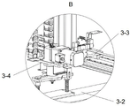
FIG. 10 is an enlarged view at B of FIG. 9 in accordance with the present invention;
FIG. 11 is a schematic structural view of a 180-degree turnover mechanism according to the present invention;
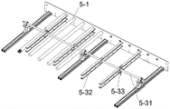
fig. 12 is a schematic structural view of the flipping unit of the present invention.
In the figure:
1. a first conveying positioning frame;
1-1, a first roller group;
1-2, a first material blocking unit; 1-21, a baffle; 1-22, overturning the cylinder; 1-23, an L-shaped hinged seat;
1-3, a first positioning unit; 1-31, a first positioning plate; 1-32, a pushing cylinder; 1-33, a guide rod; 1-34, a sliding seat; 1-35, through holes;
2. a first vertical reversing feeding and discharging device;
2-1, a second roller group;
2-2, a second material blocking unit;
2-3, a first conveyor belt; 2-31, a driving wheel; 2-32, driven wheel; 2-33, a belt; 2-34, a first rotating shaft;
2-4, a second conveyor belt;
2-5, a cylinder component; 2-51, a material pushing cylinder; 2-52, a jacking cylinder; 2-53, rotating the clamping cylinder; 2-54, push plate; 2-55, a lifting plate; 2-56, cushion blocks;
2-6, a second positioning unit;
3. a truss manipulator;
3-1, trusses; 3-2, a grabbing part; 3-3, a first mounting seat; 3-4, a second mounting seat;
4. a second conveying positioning frame;
5. a 180-degree turnover mechanism; 5-1, a third roller group; 5-2, a third material blocking unit; 5-3, a turning unit; 5-31, a second rotating shaft; 5-32, turning over the arm; 5-33, connecting piece;
6. a second vertical reversing feeding and discharging device; 7. lifting the feeding frame; 8. a double-layer conveying frame; 9. a discharging frame; 10. a keyway planer; 11. an embossing machine; 12. and (4) bending machine.
Detailed Description
The technical solutions of the present invention are further described in detail below with reference to the accompanying drawings, but the scope of the present invention is not limited to the following descriptions.
Referring to fig. 1, an embodiment of the present invention provides an automatic transportation line suitable for processing a sheet metal of a door frame, including a material table, a sheet conveying device, and a sheet processing device; the plate processing device comprises a keyway planer 10, an embossing machine 11 and a bending machine 12 which are sequentially arranged in a straight line shape; the plate conveying device comprises a first conveying positioning frame 1, a first vertical reversing feeding and discharging device 2, a truss manipulator 3, a second conveying positioning frame 4, a 180-degree turnover mechanism 5, a second vertical reversing feeding and discharging device 6, a lifting feeding frame 7, a double-layer conveying frame 8 and a discharging frame 9 which are sequentially arranged along the discharging side of the material platform; the plate conveying device is arranged in parallel to the plate processing device and is positioned on one side of a processing inlet of the plate processing device; the first vertical reversing feeding and discharging device 2 is arranged corresponding to the keyway planer 10, the second vertical reversing feeding and discharging device 6 is arranged corresponding to the embossing machine 11, and the double-layer conveying frame 8 is arranged corresponding to the bending machine 12;
the material platform is used for storing raw material plates for forming the door frame;
the keyway planer 10 is used for performing keyway machining on the back of the raw material plate;
the embossing machine 11 is used for embossing the front surface of the raw material plate;
the bending machine 12 is used for bending and forming the plate after grooving and embossing;
the first conveying positioning frame 1 is used for conveying the plates of the material platform to the first vertical reversing feeding and discharging device 2 along the long edge direction of the plates;
the first vertical reversing feeding and discharging device 2 is used for feeding the plate into or out of the keyway planer 10 along the short side direction of the plate;
the truss manipulator 3 is used for rotating the plates on the first vertical reversing feeding and discharging device 2 by 180 degrees and conveying the plates to the second conveying positioning frame 4;
the second conveying and positioning frame 4 is used for conveying the plate to the 180-degree turnover mechanism 5 along the long edge direction of the plate;
the 180-degree turnover mechanism 5 is used for turning over the plate by 180 degrees and conveying the plate to the second vertical reversing feeding and discharging device 6;
the second vertical reversing feeding and discharging device 6 is used for feeding the plate into or out of the embossing machine 11 along the short side direction of the plate;
the lifting feeding frame 7 is used for conveying the plates from the second vertical reversing feeding and discharging device 6 to the double-layer conveying frame 8;
the double-layer conveying frame 8 is used for receiving the plate processed by the embossing machine 11 and conveying the plate processed by the bending machine 12 to the discharging frame 9;
the discharging frame 9 is used for storing the formed products.
Referring to fig. 2, the first conveying and positioning frame 1 comprises a first roller group 1-1 for automatically conveying the sheet material, a first material blocking unit 1-2 for blocking or allowing the sheet material to pass through, and a first positioning unit 1-3 for positioning the long edge of the sheet material.
Referring to fig. 3, the first material blocking unit 1-2 is arranged at the discharging end of the first conveying positioning frame 1 and comprises a baffle plate 1-21 capable of being turned over by 90 degrees and a turning cylinder 1-22 for driving the baffle plate 1-21 to turn over; the support of the first conveying positioning frame 1 is provided with L-shaped hinged seats 1-23, the L-shaped hinged seats 1-23 are fixed with the baffle plates 1-21, and the L-shaped hinged seats 1-23 are provided with two hinged points which are respectively used for realizing the hinging of the baffle plates 1-21 and the support and the hinging of the baffle plates 1-21 and the tail ends of piston rods of the overturning cylinders 1-22.
Referring to fig. 4, the first positioning unit 1-3 comprises a first positioning plate 1-31 and a push cylinder 1-32 driving the first positioning plate 1-31 to move; the first positioning plate 1-31 penetrates through the rolling shaft of the first rolling shaft group 1-1 and can move along the axial direction of the rolling shaft, and a notch or a through hole 1-35 for the rolling shaft to pass through is formed in the first positioning plate 1-31; the cylinder body of the pushing cylinder 1-32 is fixed on the support below the rolling shaft and is parallel to the rolling shaft, and the tail end of the piston rod of the pushing cylinder 1-32 is fixed with the first positioning plate 1-31. Guide rods 1-33 are also symmetrically arranged at two sides of the pushing cylinder 1-32, and two ends of the guide rods 1-33 are fixed with the bracket; the bottom of the first positioning plate 1-31 is provided with a sliding seat 1-34, and the sliding seat 1-34 is connected with a guide rod 1-33 in a sliding way. The guide rods 1-33 play a role in guiding the movement of the first positioning plates 1-31, so that the process of driving the first positioning plates 1-31 to move by the pushing cylinders 1-32 is more stable and smooth, the deviation of the direction during the movement of the first positioning plates is prevented, and the positioning accuracy is ensured.
The second transporting and positioning frame 4 has the same structure as the first transporting and positioning frame 1, and therefore, the description thereof is omitted.
Referring to fig. 5, the first vertical reversing feeding and discharging device 2 comprises a second roller group 2-1, a second blocking unit 2-2 for blocking or allowing the plate to pass through, and a belt feeding group perpendicular to the conveying direction of the second roller group 2-1; the belt feeding group comprises a first belt group and a second belt group, the first belt group comprises a plurality of first conveyor belts 2-3 capable of synchronously lifting, and the first conveyor belts 2-3 are arranged in the roller gaps of the second roller group 2-1 in an inserting manner; the second belt group comprises a plurality of second conveyor belts 2-4 capable of synchronously lifting and descending and cylinder assemblies 2-5 for feeding and discharging materials, and the second conveyor belts 2-4 and the first conveyor belts 2-3 are arranged in a staggered mode.
Referring to fig. 6, each of the first conveyor belts 2-3 has the same structure as the second conveyor belt 2-4, and includes a driving wheel 2-31 located in the middle, driven wheels 2-32 located at both ends, and a second motor for driving the driving wheel 2-31 to rotate; the driving wheels 2-31 and the driven wheels 2-32 are in transmission connection through belts 2-33, two adjacent driving wheels 2-31 are coaxially connected through first rotating shafts 2-34, and the first rotating shafts 2-34 are in transmission connection with output shafts of the second motors. When the materials are not fed, the heights of the top surfaces of the first conveyor belt 2-3 and the second conveyor belt 2-4 are lower than the top surfaces of the rollers of the second roller group 2-1; when the plate needs to be reversed, the first conveyor belt 2-3 and the second conveyor belt 2-4 are driven by the lifting device to rise in height, so that the plate can be separated from the second roller group 2-1 and fall into the first conveyor belt 2-3, and subsequent conveying is facilitated.
Referring to fig. 7, the cylinder assembly 2-5 comprises a pushing cylinder 2-51, a jacking cylinder 2-52 and a rotary clamping cylinder 2-53; the material pushing cylinder 2-51 is used for pushing or pulling the plate out of the keyway planer 10; the rotary clamping cylinders 2-53 are used for clamping plates; the jacking cylinder 2-52 is used for adjusting the height of the rotary clamping cylinder 2-53. The cylinder body mounting direction of the material pushing cylinder 2-51 is parallel to the conveying direction of the second belt group; a push plate 2-54 is fixed at the tail end of a piston rod of the material pushing cylinder 2-51, a cylinder body of the jacking cylinder 2-52 is fixed at the lower end of the push plate 2-54, and a lifting plate 2-55 is fixed at the tail end of a piston rod of the jacking cylinder 2-52; the cylinder body of the rotary clamping cylinder 2-53 is arranged on a lifting plate 2-55, and a cushion block 2-56 which is matched with a rotating arm of the rotary clamping cylinder 2-53 to clamp materials is arranged on the lifting plate 2-55.
When the plate is conveyed to the inlet of the keyway planer 10 through the second conveyor belt 2-4, the piston rods of the pushing cylinders 2-51 extend to drive the pushing plates 2-54 to push forwards, so that the plate is pushed into the device from the inlet of the device. The plates are sent out to the opening of the equipment after being processed in the equipment, and at the moment, the piston rods of the jacking cylinders 2-52 extend to push the lifting plates 2-55 to ascend so as to drive the rotary clamping cylinders 2-53 to ascend; at the moment, a piston rod of the rotary clamping cylinder 2-53 extends, the swing arm rotates to one side close to the plate, the piston rod of the rotary clamping cylinder 2-53 contracts, and the swing arm presses downwards to be matched with the cushion block 2-56 to complete clamping of the plate; and then the piston rod of the pushing cylinder 2-51 is contracted and reset, and the push plate 2-54 is pulled to reset, so that the plate is dragged out of the equipment port to the second conveyor belt 2-4.
Referring to fig. 1, two recessing machines 10 are provided, and a transition transportation frame is provided between two neighboring recessing machines 10. The second material blocking unit 2-2 is arranged on the first vertical reversing feeding and discharging device 2 to block or release the plate, and when incoming materials need to enter the first grooving machine 10 for processing, the baffle is erected to block and limit the end part of the plate, so that the plate can be conveniently and subsequently conveyed in a reversing way; when there is the supplied materials at the rear, the baffle can turn over to the horizontality, allows panel through getting into second platform keyway planer 10 to can realize the simultaneous processing of two equipment, guarantee the continuation of production, orderly, high-efficient going on.
Referring to fig. 6 and 8, a second positioning unit 2-6 for positioning the long edge of the plate is arranged on the second belt set, and the second positioning unit 2-6 comprises a second positioning plate with a height capable of being lifted. The second positioning plate is used for positioning the long edge of the plate close to the edge before the plate enters the equipment, so that the position accuracy of the plate is ensured, and the processing quality of the current process is ensured; after the positioning is finished, the second positioning plate descends to allow the plate to be conveyed into the equipment continuously, and the second positioning plate resets after the plate enters the equipment; when the plate is processed and exits the equipment, the second positioning plate aligns the long edge of the plate by the side again, and performs pre-positioning before the plate enters the lower-stage process, so that the position precision of the plate is further ensured.
The second vertical reversing feeding and discharging device 6 has the same structure as the first vertical reversing feeding and discharging device 2, and therefore, the detailed description is omitted here.
Referring to fig. 9, the truss robot 3 includes a truss 3-1 and a robot body disposed on the truss 3-1 to be reciprocally movable along the truss 3-1; the manipulator body comprises a grabbing part 3-2 and a supporting part; referring to fig. 10, the supporting portion includes a first mounting base 3-3 slidably connected to the truss 3-1 and a second mounting base 3-4 capable of being lifted and lowered with respect to the first mounting base 3-3; the grabbing part 3-2 is arranged on the second mounting seat 3-4 and is rotatably connected with the second mounting seat 3-4, and a fourth motor for driving the grabbing part 3-2 to rotate is arranged on the second mounting seat 3-4. The grabbing part 3-2 adopts a vacuum sponge sucker, and the plate is adsorbed or released by pumping or inflating, and the specific principle is the prior art and is not repeated herein.
Because the dadoing and knurling are gone on respectively in the reverse side and the front of panel, and the processing region all keeps away from one side of hole site on the panel, and for convenient processing, panel behind the dadoing needs 180 degrees rotations to turn over the face again after switching over to guarantee that the region of knurling processing is located the one side that is close to coining mill 11 entry.
The truss 3-1 is located between the grooving process and the embossing process and arranged along the same direction of the linear production line, when the grooving process is finished on the plate and the plate is output from the grooving machine 10, the plate is adsorbed by the grabbing part 3-2, the grabbing part 3-2 is driven by the fourth motor to rotate, the plate is driven to complete 180-degree rotation reversing, and then the plate is conveyed to the embossing process along the truss 3-1. The movement of the manipulator body on the truss 3-1 can be realized by arranging structures such as synchronous pulleys or lead screws.
Referring to fig. 11, the 180-degree turnover mechanism 5 comprises a third roller group 5-1 for automatically conveying the plate, a third material blocking unit 5-2 for blocking or allowing the plate to pass through, and a turnover unit 5-3 for turning over the plate 180 degrees along the long side direction thereof; referring to fig. 12, the turning unit 5-3 comprises a second rotating shaft 5-31, a plurality of turning arms 5-32 axially spaced along the second rotating shaft 5-31, and a third motor for driving the second rotating shaft 5-31 to rotate; the overturning arms 5-32 are arranged in the roller gaps of the third roller group 5-1, and the overturning arms 5-32 comprise upper arms and lower arms which are parallel to each other; the centers of the upper arm and the lower arm are fixed with a second rotating shaft 5-31 through a connecting piece 5-33, and the second rotating shaft 5-31 is in transmission connection with an output shaft of a third motor.
The second rotating shaft 5-31 divides the conveying table surface into two areas which are used for inputting and outputting the plates respectively; when the turning arms 5-32 are not turned, the bottom surfaces of the upper arms are higher than the top surfaces of the rollers of the third roller group 5-1, and the top surfaces of the lower arms are lower than the top surfaces of the rollers of the third roller group 5-1. The plate enters the input area in a state that the back face of the plate faces upwards, is positioned between the upper arm and the lower arm, and cannot be directly output under the blocking of the third material blocking unit 5-2; and then the third motor drives the second rotating shaft 5-31 to rotate, and drives the turnover arm 5-32 to turn over for 180 degrees, so that the plate enters an output area in a state of being turned over for 180 degrees and the right side of the plate is upward and is conveyed to an embossing process.
The lifting feeding frame 7 comprises a fourth roller group for automatically conveying the plates and a fourth material blocking unit for blocking or allowing the plates to pass through, and the height of the lifting feeding frame 7 is adjustable. Due to the height difference between the embossing machine 11 and the processing inlet of the bending machine 12, the height difference exists between the second vertical reversing feeding and discharging device 6 and the feeding table of the double-layer conveying frame 8. Through setting up height-adjustable's lift pay-off frame 7 as the transition of panel between these two devices, solved the inconvenient problem of panel operation because of highly inconsistent bringing, the going on of convenient follow-up step of bending.
The double-layer conveying frame 8 comprises an upper conveying belt and a lower conveying belt, one conveying belt is used for receiving plates to be bent, the plates are conveyed from the lifting feeding frame 7, a worker holds the plates to process the plates at a processing opening of the bending machine 12, and after processing is completed, the worker puts a formed part to the other layer of the double-layer conveying frame 8 to enable the formed part to be conveyed to the discharging frame 9 for temporary storage.
In the invention, the second material blocking unit 2-2, the third material blocking unit 5-2 and the fourth material blocking unit have the same structure as the first material blocking unit 1-2, and are not described herein again.
In the invention, the first roller group 1-1, the second roller group 2-1, the third roller group 5-1 and the fourth roller group have the same structure and respectively comprise a plurality of rollers arranged at intervals and a first motor for driving the plurality of rollers to synchronously rotate, and the transmission between the first motor and the rollers can be realized by arranging a chain wheel and a chain or other transmission structures.
All the liftable components can be realized by adopting an air cylinder, an electric cylinder or other lifting devices, and can be selected by a person skilled in the art according to the arrangement requirement on the site.
The panel processing device and the panel conveying device in the invention can be provided with photoelectric detection switches for detecting the incoming material information or position information of the panel, and the photoelectric detection switches are used as the input of control signals, which is well known by those skilled in the art, and the specific set points and number can be adjusted by those skilled in the art according to the requirement of a production line, so that the details are not described herein.
The working principle and the using process of the invention are as follows: the raw material plate is conveyed from the material table to the first vertical reversing feeding and discharging device 2 through the first conveying and positioning frame 1 along the long side direction of the raw material plate in a state that the back face of the raw material plate faces upwards, then enters the keyway planer 10 along the short side direction of the raw material plate under the transportation of the belt feeding group, and is withdrawn from the keyway planer 10 to the first vertical reversing feeding and discharging device 2 along the short side direction after the keyway planer is processed; after the truss manipulator 3 grabs the plate, 180-degree rotary reversing is carried out on the plate, then the plate is conveyed to a second conveying positioning frame 4, and then the plate enters a 180-degree turnover mechanism 5 along the long edge direction of the plate; the plates are turned over along the long edge direction under the drive of the turning arms 5-32, and enter the second vertical reversing feeding and discharging device 6 in a state that the front faces of the plates are upward; plate gets into coining mill 11 along its minor face direction, withdraws from to the perpendicular switching-over business turn over material device 6 of second along the minor face direction from coining mill 11 after embossing process accomplishes, and through the transition of lift pay-off frame 7 and transport, plate is delivered to the upper conveyer belt of double-deck carriage 8, is handed supplementary by the workman and is accomplished the processing of bending at bender 12, and plate after the shaping is delivered to play work or material rest 9 and is kept in through the lower floor conveyer belt of double-deck carriage 8.
The foregoing is illustrative of the preferred embodiments of this invention, and it is to be understood that the invention is not limited to the precise form disclosed herein and that various other combinations, modifications, and environments may be resorted to, falling within the scope of the concept as disclosed herein, either as described above or as apparent to those skilled in the relevant art. And that modifications and variations may be effected by those skilled in the art without departing from the spirit and scope of the invention as defined by the appended claims.
Claims (9)
1. Automatic conveying line suitable for door frame sheet metal processing, including material platform, panel conveyor and panel processingequipment, its characterized in that: the plate processing device comprises a keyway planer, an embossing machine and a bending machine which are sequentially arranged in a straight line shape; the plate conveying device comprises a first conveying positioning frame, a first vertical reversing feeding and discharging device, a truss manipulator, a second conveying positioning frame, a 180-degree turnover mechanism, a second vertical reversing feeding and discharging device, a lifting feeding frame, a double-layer conveying frame and a discharging frame which are sequentially arranged along the discharging side of the material platform; the plate conveying device is arranged in parallel to the plate processing device and is positioned on one side of a processing inlet of the plate processing device; the first vertical reversing feeding and discharging device is arranged corresponding to the keyway planer, the second vertical reversing feeding and discharging device is arranged corresponding to the embossing machine, and the double-layer conveying frame is arranged corresponding to the bending machine;
the material platform is used for storing raw material plates for forming the door frame;
the keyway planer is used for carrying out keyway machining on the back of the raw material plate;
the embossing machine is used for embossing the front surface of the raw material plate;
the bending machine is used for bending and forming the plate after grooving and embossing;
the first conveying and positioning frame is used for conveying the plates of the material platform to the first vertical reversing feeding and discharging device along the long edge direction of the plates;
the first vertical reversing feeding and discharging device is used for feeding the plate into or discharging the plate out of the keyway planer along the short side direction of the plate;
the truss manipulator is used for rotating the plates on the first vertical reversing feeding and discharging device by 180 degrees and conveying the plates to the second conveying positioning frame;
the second conveying positioning frame is used for conveying the plate to the 180-degree turnover mechanism along the long edge direction of the plate;
the 180-degree turnover mechanism is used for turning over the plate by 180 degrees and conveying the plate to the second vertical reversing feeding and discharging device;
the second vertical reversing feeding and discharging device is used for feeding the plate into or out of the embossing machine along the short side direction of the plate;
the lifting feeding frame is used for conveying the plates from the second vertical reversing feeding and discharging device to the double-layer conveying frame;
the double-layer conveying frame is used for receiving the plate processed by the embossing machine and conveying the plate processed by the bending machine to the discharging frame;
the discharging rack is used for storing formed products;
the first conveying positioning frame and the second conveying positioning frame are identical in structure and are respectively provided with a first roller group for automatically conveying the plates, a first material blocking unit for blocking or allowing the plates to pass through and a first positioning unit for positioning the long edges of the plates;
the first vertical reversing feeding and discharging device and the second vertical reversing feeding and discharging device are identical in structure and are respectively provided with a second roller group, a second material blocking unit for blocking or allowing a plate to pass through and a belt feeding group perpendicular to the conveying direction of the second roller group;
the 180-degree turnover mechanism comprises a third roller group for automatically conveying the plate, a third material blocking unit for blocking or allowing the plate to pass through and a turnover unit for turning over the plate by 180 degrees along the long side direction of the plate;
the lifting feeding frame comprises a fourth roller group for automatically conveying the plates and a fourth material blocking unit for blocking or allowing the plates to pass through, and the height of the lifting feeding frame is adjustable;
the first roller group, the second roller group, the third roller group and the fourth roller group are identical in structure and respectively comprise a plurality of rollers arranged at intervals and a first motor used for driving the plurality of rollers to rotate synchronously.
2. The automatic conveying line suitable for door frame sheet metal working according to claim 1, characterized in that: the belt feeding group comprises a first belt group and a second belt group, the first belt group comprises a plurality of first conveyor belts capable of synchronously lifting, and the first conveyor belts are arranged in the roller gaps of the second roller group in an inserting manner; the second belt set comprises a plurality of second conveyor belts capable of synchronously lifting and a cylinder assembly for feeding and discharging materials, and the second conveyor belts and the first conveyor belts are arranged in a staggered mode.
3. The automatic conveying line suitable for door frame sheet metal machining according to claim 2, characterized in that: the cylinder assembly comprises a material pushing cylinder, a jacking cylinder and a rotary clamping cylinder; the material pushing cylinder is used for pushing or dragging the plate out of the keyway planer or the embossing machine; the rotary clamping cylinder is used for clamping a plate; the jacking cylinder is used for adjusting the height of the rotary clamping cylinder.
4. The automatic conveying line suitable for door frame sheet metal working according to claim 2, characterized in that: each first conveyor belt is identical to each second conveyor belt in structure and comprises a driving wheel positioned in the middle, driven wheels positioned at two ends and a second motor for driving the driving wheel to rotate; the driving wheels are in transmission connection with the driven wheels through belts, two adjacent driving wheels are in coaxial connection through a first rotating shaft, and the first rotating shaft is in transmission connection with an output shaft of the second motor.
5. The automatic conveying line suitable for door frame sheet metal machining according to claim 2, characterized in that: and a second positioning unit for positioning the long edge of the plate is arranged on the second belt set.
6. The automatic conveying line suitable for door frame sheet metal machining according to claim 1, characterized in that: the overturning unit comprises a second rotating shaft, a plurality of overturning arms arranged at intervals along the axial direction of the second rotating shaft and a third motor for driving the second rotating shaft to rotate; the overturning arm is arranged in a roller gap of the third roller group and comprises an upper arm and a lower arm which are parallel to each other; the centers of the upper arm and the lower arm are fixed with the second rotating shaft through a connecting piece; and the second rotating shaft is in transmission connection with an output shaft of the third motor.
7. The automatic conveying line suitable for door frame sheet metal working according to claim 1, characterized in that: the first positioning unit comprises a first positioning plate which can move along the axial direction of the rollers of the first roller group.
8. The automatic conveying line suitable for door frame sheet metal machining according to claim 5, characterized in that: the second positioning unit comprises a second positioning plate with liftable height.
9. The automatic conveying line suitable for door frame sheet metal working according to claim 1, characterized in that: first fender material unit, second fender material unit, third fender material unit and fourth fender material unit structure are the same, all include the baffle that can 90 degrees upsets.
Priority Applications (1)
| Application Number | Priority Date | Filing Date | Title |
|---|---|---|---|
| CN202211298774.8A CN115351558B (en) | 2022-10-24 | 2022-10-24 | Automatic conveying line suitable for processing door frame sheet metal |
Applications Claiming Priority (1)
| Application Number | Priority Date | Filing Date | Title |
|---|---|---|---|
| CN202211298774.8A CN115351558B (en) | 2022-10-24 | 2022-10-24 | Automatic conveying line suitable for processing door frame sheet metal |
Publications (2)
| Publication Number | Publication Date |
|---|---|
| CN115351558A true CN115351558A (en) | 2022-11-18 |
| CN115351558B CN115351558B (en) | 2023-01-31 |
Family
ID=84007965
Family Applications (1)
| Application Number | Title | Priority Date | Filing Date |
|---|---|---|---|
| CN202211298774.8A Active CN115351558B (en) | 2022-10-24 | 2022-10-24 | Automatic conveying line suitable for processing door frame sheet metal |
Country Status (1)
| Country | Link |
|---|---|
| CN (1) | CN115351558B (en) |
Citations (17)
| Publication number | Priority date | Publication date | Assignee | Title |
|---|---|---|---|---|
| JP2014061539A (en) * | 2012-09-24 | 2014-04-10 | Toyota Motor East Japan Inc | Double blank separator |
| KR101390939B1 (en) * | 2013-02-18 | 2014-05-02 | 주식회사한우공영 | Automatic equipment for manufacturing muffler of vehicle |
| CN103786024A (en) * | 2012-10-29 | 2014-05-14 | 浙江大学 | Fully-automatic advertising logo bending machine |
| CN104722610A (en) * | 2015-04-02 | 2015-06-24 | 佛山市南海九洲普惠风机有限公司 | Panel bending automatic production line |
| CN104759894A (en) * | 2015-04-20 | 2015-07-08 | 扬州恒佳机械有限公司 | Machining production line for sheet metal |
| CN204449892U (en) * | 2014-10-31 | 2015-07-08 | 江山市百事得机械设备制造厂 | A kind of sheet material cuts the clear limit of saw and sanding production line automatically |
| CN107052813A (en) * | 2017-05-28 | 2017-08-18 | 厦门耐立特包装科技有限公司 | A kind of semi-automatic production line of steel frame construction packing case |
| CN108747397A (en) * | 2018-06-15 | 2018-11-06 | 江苏金三力机械制造有限公司 | A kind of steel arch-shelf connecting plate automatic shearing rushes production line and its production method |
| CN109047398A (en) * | 2018-08-15 | 2018-12-21 | 姜云峰 | A kind of sheet fabrication center |
| CN109909687A (en) * | 2019-02-27 | 2019-06-21 | 江苏阿尔菲特科技有限公司 | A kind of metal plate production technology and its production system based on industrial automation |
| CN213317301U (en) * | 2020-06-19 | 2021-06-01 | 山东友联工程有限公司 | Plate guiding device matched with flat plate cutting machine |
| CN113333515A (en) * | 2021-07-05 | 2021-09-03 | 深圳市驭智装备技术有限公司 | Plate bending processing method |
| CN113828688A (en) * | 2021-08-13 | 2021-12-24 | 四川和乐门业有限公司 | Sheet metal conveying line suitable for door leaf production and door leaf production process |
| CN113879823A (en) * | 2021-09-28 | 2022-01-04 | 浙江奥煌卫浴有限公司 | Plate conveying device of automatic drilling machine for furniture plates |
| CN113911669A (en) * | 2021-12-14 | 2022-01-11 | 四川和乐门业有限公司 | Hot pressing production line for door processing |
| CN215754930U (en) * | 2021-08-06 | 2022-02-08 | 四川和乐门业有限公司 | Turnover positioning device for door leaf |
| CN215746002U (en) * | 2021-08-06 | 2022-02-08 | 四川和乐门业有限公司 | Door leaf flanging conveying device |
-
2022
- 2022-10-24 CN CN202211298774.8A patent/CN115351558B/en active Active
Patent Citations (17)
| Publication number | Priority date | Publication date | Assignee | Title |
|---|---|---|---|---|
| JP2014061539A (en) * | 2012-09-24 | 2014-04-10 | Toyota Motor East Japan Inc | Double blank separator |
| CN103786024A (en) * | 2012-10-29 | 2014-05-14 | 浙江大学 | Fully-automatic advertising logo bending machine |
| KR101390939B1 (en) * | 2013-02-18 | 2014-05-02 | 주식회사한우공영 | Automatic equipment for manufacturing muffler of vehicle |
| CN204449892U (en) * | 2014-10-31 | 2015-07-08 | 江山市百事得机械设备制造厂 | A kind of sheet material cuts the clear limit of saw and sanding production line automatically |
| CN104722610A (en) * | 2015-04-02 | 2015-06-24 | 佛山市南海九洲普惠风机有限公司 | Panel bending automatic production line |
| CN104759894A (en) * | 2015-04-20 | 2015-07-08 | 扬州恒佳机械有限公司 | Machining production line for sheet metal |
| CN107052813A (en) * | 2017-05-28 | 2017-08-18 | 厦门耐立特包装科技有限公司 | A kind of semi-automatic production line of steel frame construction packing case |
| CN108747397A (en) * | 2018-06-15 | 2018-11-06 | 江苏金三力机械制造有限公司 | A kind of steel arch-shelf connecting plate automatic shearing rushes production line and its production method |
| CN109047398A (en) * | 2018-08-15 | 2018-12-21 | 姜云峰 | A kind of sheet fabrication center |
| CN109909687A (en) * | 2019-02-27 | 2019-06-21 | 江苏阿尔菲特科技有限公司 | A kind of metal plate production technology and its production system based on industrial automation |
| CN213317301U (en) * | 2020-06-19 | 2021-06-01 | 山东友联工程有限公司 | Plate guiding device matched with flat plate cutting machine |
| CN113333515A (en) * | 2021-07-05 | 2021-09-03 | 深圳市驭智装备技术有限公司 | Plate bending processing method |
| CN215754930U (en) * | 2021-08-06 | 2022-02-08 | 四川和乐门业有限公司 | Turnover positioning device for door leaf |
| CN215746002U (en) * | 2021-08-06 | 2022-02-08 | 四川和乐门业有限公司 | Door leaf flanging conveying device |
| CN113828688A (en) * | 2021-08-13 | 2021-12-24 | 四川和乐门业有限公司 | Sheet metal conveying line suitable for door leaf production and door leaf production process |
| CN113879823A (en) * | 2021-09-28 | 2022-01-04 | 浙江奥煌卫浴有限公司 | Plate conveying device of automatic drilling machine for furniture plates |
| CN113911669A (en) * | 2021-12-14 | 2022-01-11 | 四川和乐门业有限公司 | Hot pressing production line for door processing |
Also Published As
| Publication number | Publication date |
|---|---|
| CN115351558B (en) | 2023-01-31 |
Similar Documents
| Publication | Publication Date | Title |
|---|---|---|
| JP2722944B2 (en) | Work transfer system | |
| US4941793A (en) | System for sending-off press-formed parts | |
| CN115417121A (en) | Vertical reversing feeding and discharging conveying device suitable for processing door frame metal plate | |
| CN215709795U (en) | Auto parts processing conveyor | |
| CN115351558B (en) | Automatic conveying line suitable for processing door frame sheet metal | |
| CN113977285A (en) | Automatic sawing, punching and milling processing equipment for aluminum template | |
| CN111606026B (en) | Automatic stores pylon equipment of cell-phone battery case of unloading on unilateral | |
| CN111036965A (en) | Intelligent milling forming machine for engineering plate | |
| CN112722427B (en) | Automatic stacking device for elevator protection door | |
| KR100554971B1 (en) | Automatic Device for Transportation and Loading of Strip | |
| CN110394681A (en) | A kind of big piston pin multiaxis truss robot one drag two numerical control machine | |
| CN209793109U (en) | feeding equipment and welding seam processing system | |
| CN218464686U (en) | Motor end cover feeding device | |
| CN211681108U (en) | Material feeding mechanism of multifunctional milling material forming machine | |
| CN217625606U (en) | Integrative equipment of keeping in is carried to sheet material | |
| CN219155889U (en) | Mould stacking device and automatic stacking system | |
| CN220722726U (en) | Fixed four-axis robot | |
| CN218859802U (en) | Device for die stacking and automatic stacking system | |
| CN220033304U (en) | Feeding device for sectional materials | |
| CN220466287U (en) | Tubular product piling bin | |
| CN219135503U (en) | Automatic logistics feeding equipment | |
| CN219990457U (en) | Double-layer feeding conveying line | |
| CN218426117U (en) | Three-dimensional material storehouse of panel class | |
| CN114804604B (en) | Large-breadth glass laser cutting device | |
| CN217457414U (en) | Automatic feeding mechanism for cement pouring mold production line |
Legal Events
| Date | Code | Title | Description |
|---|---|---|---|
| PB01 | Publication | ||
| PB01 | Publication | ||
| SE01 | Entry into force of request for substantive examination | ||
| SE01 | Entry into force of request for substantive examination | ||
| GR01 | Patent grant | ||
| GR01 | Patent grant |