CN115339580A - Offshore floating platform integrating booster station and data center - Google Patents
Offshore floating platform integrating booster station and data center Download PDFInfo
- Publication number
- CN115339580A CN115339580A CN202211036853.1A CN202211036853A CN115339580A CN 115339580 A CN115339580 A CN 115339580A CN 202211036853 A CN202211036853 A CN 202211036853A CN 115339580 A CN115339580 A CN 115339580A
- Authority
- CN
- China
- Prior art keywords
- cabin
- data center
- pipeline
- sea
- layer
- Prior art date
- Legal status (The legal status is an assumption and is not a legal conclusion. Google has not performed a legal analysis and makes no representation as to the accuracy of the status listed.)
- Pending
Links
Images


Classifications
-
- B—PERFORMING OPERATIONS; TRANSPORTING
- B63—SHIPS OR OTHER WATERBORNE VESSELS; RELATED EQUIPMENT
- B63B—SHIPS OR OTHER WATERBORNE VESSELS; EQUIPMENT FOR SHIPPING
- B63B35/00—Vessels or similar floating structures specially adapted for specific purposes and not otherwise provided for
- B63B35/44—Floating buildings, stores, drilling platforms, or workshops, e.g. carrying water-oil separating devices
-
- Y—GENERAL TAGGING OF NEW TECHNOLOGICAL DEVELOPMENTS; GENERAL TAGGING OF CROSS-SECTIONAL TECHNOLOGIES SPANNING OVER SEVERAL SECTIONS OF THE IPC; TECHNICAL SUBJECTS COVERED BY FORMER USPC CROSS-REFERENCE ART COLLECTIONS [XRACs] AND DIGESTS
- Y02—TECHNOLOGIES OR APPLICATIONS FOR MITIGATION OR ADAPTATION AGAINST CLIMATE CHANGE
- Y02E—REDUCTION OF GREENHOUSE GAS [GHG] EMISSIONS, RELATED TO ENERGY GENERATION, TRANSMISSION OR DISTRIBUTION
- Y02E10/00—Energy generation through renewable energy sources
- Y02E10/70—Wind energy
- Y02E10/727—Offshore wind turbines
Landscapes
- Engineering & Computer Science (AREA)
- Architecture (AREA)
- Civil Engineering (AREA)
- Structural Engineering (AREA)
- Chemical & Material Sciences (AREA)
- Combustion & Propulsion (AREA)
- Mechanical Engineering (AREA)
- Ocean & Marine Engineering (AREA)
- Filling Or Discharging Of Gas Storage Vessels (AREA)
Abstract
An offshore floating platform integrating a booster station and a data center is connected with a fan of a wind power plant, a land substation or a centralized control center. The upper floating body of the platform is fixed above the lower floating body through the upright post, the upper floating body is provided with an upper deck and a lower deck, and the lower floating body is provided with a ballast tank layer and a data center tank layer. One end of the ballast tank sea pipeline and one end of the cabin sea pipeline are communicated with the data center cabin layer, and the other end of the ballast tank sea pipeline and the cabin sea pipeline are connected into the sea. Compared with a supporting structure for independently building a data center on the sea, the offshore booster station and the data center can share one platform, so that the construction cost can be greatly saved, and the resources can be reasonably integrated and utilized. The electricity consumption cost can be greatly reduced, and for a data center with high energy consumption, the operation cost can be greatly reduced. The seawater is utilized for natural cooling, so that the later-stage operation cost is further reduced.
Description
Technical Field
The invention belongs to the field of construction and design of offshore data and booster stations, and particularly relates to an offshore floating platform combining a booster station and a data center.
Background
Wind energy is used as a clean new energy source and has been widely applied in China. However, the wind farm occupies a large area, so that the land wind farm and the near-shore wind farm in China are developed almost completely, and the deep navy is required in the future. The deep and remote sea wind energy resource is more abundant, but the distance from the land is far away, a marine booster station needs to be built, the wind energy is converted into electric energy which is then boosted after being integrated, and the electric energy is transmitted to the land in a low-loss manner and then is merged into a power grid for use. At present, a jacket type booster station close to the shore is mainly used as a marine booster station, but the form is not only high in cost, but also not suitable for deep and distant sea areas with too deep water depth.
In the current internet and big data era, the safe and efficient storage of mass data is a problem faced by various enterprises. At present, a common data center is built on land, and the problems of large occupied space, high energy consumption, large heat productivity and the like exist. The high energy consumption causes the data center to be sensitive to electricity cost, and the energy consumed by the data center for cooling can account for 40% of the total energy consumption of the data center due to the extremely large heat generation of the server. Therefore, it is necessary to develop a solution for reducing the cooling power consumption thereof. Some projects try to place the data center on the seabed, and although the method has the advantages of not occupying land resources, fully utilizing seawater to dissipate heat naturally and reducing cooling energy consumption, the method also has the problems of high offshore installation cost, inconvenience in later maintenance and the like.
Disclosure of Invention
In order to solve the problems, the invention provides an offshore floating platform integrating a booster station and a data center, aiming at achieving the purposes of integrating the electric energy of a deep and open sea offshore wind field and boosting the electric energy, being compatible with the offshore data center and sharing the same platform, and adopting the technical scheme that:
an offshore floating platform integrating a booster station and a data center is close to a wind power plant, communicated with a fan of the wind power plant through a submarine cable and connected with a land transformer substation or a centralized control center through a submarine photoelectric composite cable.
The upper portion body of platform passes through the stand and supports in lower part body top, the stand top is connected with upper portion body lower surface, the lower part body is run through to the stand bottom, the upper portion body has upper deck and lower deck, the lower part body has ballast tank layer and data center cabin layer, the upper portion body is located the sea top, the lower part body is located the sea below, the upper portion body has upper deck and lower deck, the lower part body is provided with upper and lower two-layer, the upper strata is the ballast tank layer, the lower floor is the data center cabin layer.
A GIS switch equipment room, a main step-up transformer room, transformer cooling equipment, a crane, a living and office area and a helicopter platform are arranged on the upper deck, and a control system room, a diesel generator room and a mechanical equipment room are arranged on the lower deck.
Continuous ballast tanks are laid between adjacent columns to form a ballast tank layer, continuous tanks are laid to form a data center tank layer, the middles of the ballast tank layer and the data center tank layer are hollow, an IDC module tank is arranged in the tank of the data center tank layer, and a temperature sensor is arranged in the IDC module tank.
Inside the stand, laid ventilative pipeline and nitrogen gas supply pipe way from bottom to top, the nitrogen gas supply pipe way top is inserted in the mechanical equipment room, and the bottom is inserted in the IDC module cabin, and ventilative pipeline bottom is inserted in the cabin on data center cabin layer or the ballast cabin on ballast cabin layer, and the top upwards extends and extends the upper deck.
A ballast tank sea pipeline and a cabin sea pipeline are also arranged in the upright column, the ballast tank sea pipeline is positioned in the upright column of the ballast tank layer, one end of the ballast tank sea pipeline is communicated with the data center tank layer, and the other end of the ballast tank sea pipeline is connected into the sea; the cabin sea-going pipeline is positioned in the stand column of the data center cabin layer, one end of the cabin sea-going pipeline is communicated with the data center cabin layer, and the other end of the cabin sea-going pipeline is connected into the sea.
The bottom still is provided with the ballast pump in the stand, and the ballast pump is connected with ballast pump pipeline and water drainage pipeline, and in the cabin on ballast pump pipeline access data center tank layer, water drainage pipeline upwards extended, passed lower deck and inserted in the sea in the stand is inside, and the ballast tank on ballast tank layer stretches out to have the drainage branch pipeline to converge into the ballast pump pipeline, is provided with first valve on the drainage branch pipeline, is provided with the second valve on the ballast pump pipeline.
The IDC module cabin is provided with an IDC module cabin base, an IDC module cabin shell is fixed on the IDC module cabin base, a cooling liquid collecting tank is arranged in the bottom of the IDC module cabin shell, cooling liquid is contained in the cooling liquid collecting tank, one row or more than one row of equipment cabinets are fixed in the IDC module cabin shell, each row of equipment cabinets is provided with a plurality of equipment cabinets, each equipment cabinet is provided with a cooling cabin and a heat exchange coil, the bottom of the cooling cabin is connected with a cooling liquid circulating pump, the top of the cooling cabin is communicated with one end of the heat exchange coil, the other end of the heat exchange coil extends into the cooling liquid collecting tank, and the cooling cabin is located between the equipment cabinets and the IDC module cabin shell.
The offshore floating platform integrating the booster station and the data center is characterized in that the IDC module cabin is a watertight cabin, the IDC module cabin is made of carbon steel, and the outer surface of the IDC module cabin is coated with protective paint and welded with a zinc block.
The offshore floating platform integrating the booster station and the data center is characterized in that the IDC module cabin is connected with the control system room through an umbilical cable of an optical fiber, and the umbilical cable of the optical fiber and the cable are located in the upright post and fixed through an optical cable bracket.
The offshore floating platform integrating the booster station and the data center is further fixed on the sea surface through anchor chains, one ends of the anchor chains are connected with the offshore floating platform through chain stoppers, and the other ends of the anchor chains are connected with seabed anchor piles.
Above-mentioned offshore floating platform that fuses booster station and data center, further, be provided with electric gate valve and electric butterfly valve on the cabin leads to the sea pipeline, and electric gate valve sets up near sea water department at the cabin leads to the sea pipeline, and electric butterfly valve keeps away from sea water department at the cabin leads to the sea pipeline and sets up.
The offshore floating platform integrating the booster station and the data center is further provided with a third valve on the sea pipeline of the ballast tank.
The offshore floating platform integrating the booster station and the data center is characterized in that an air/nitrogen supply system and a fire fighting system are further arranged in the mechanical equipment room, the top end of the nitrogen supply pipeline is connected with the air/nitrogen supply system, and the bottom end of the nitrogen supply pipeline is connected into the IDC module cabin shell.
The offshore floating platform integrating the booster station and the data center further comprises a cooling device and an anti-seismic raft seat arranged in the main booster transformer chamber.
The offshore floating platform integrating the booster station and the data center is characterized in that a base is padded at the bottom of an equipment cabinet in an IDC module cabin shell, and the liquid level in a cooling liquid collecting pool is lower than or equal to the height of the base.
In the offshore floating platform integrating the booster station and the data center, the bottom plate of the IDC module cabin shell is a titanium alloy thin plate.
The beneficial effects of the invention are:
for the booster station side:
1. the data center investor can share part of the cost of the offshore floating platform, so that the total investment cost is greatly reduced.
2. The equipment such as distribution, vary voltage, automatically controlled and pump, valve can consider when the design and data center sharing, and the other side can share a part of equipment purchase cost like this.
3. A part of electric energy converted from wind energy is directly consumed by the data center, so that electric energy needing to be transmitted remotely is reduced, and the method is favorable for reducing power transmission cost and power transmission loss.
4. The operation of the offshore booster station is generally attended by people, and the people can monitor the operation condition of the data center and charge management fees to one side of the data center, so that the operation cost of the booster station is reduced.
For the data center side:
1. compared with a supporting structure for independently building a data center on the sea, the platform shared by the offshore booster station and the supporting structure can greatly save construction cost and reasonably integrate and utilize resources.
2. Distribution, vary voltage, electrically controlled device and equipment such as pump, valve can consider when the design and step up the station sharing, can greatly reduced equipment's purchase cost like this.
3. With data center setting around the wind field, the power consumption cost can greatly reduced, and this can greatly reduced operation cost to the data center that the power consumption is higher.
4. Set up data center in the sea water, utilize sea water natural cooling, it is good not only to compare traditional forced air cooling effect, moreover can greatly reduced cooling energy consumption, further reduced later stage operation cost.
5. Compared with a data center generally arranged in seawater, the sea condition is severe sometimes, loads such as wind, wave and flow can put higher requirements on the umbilical cable, and the umbilical cable is easy to damage and inconvenient to maintain. The data center is arranged in the cabin, so that the environment is mild, and the defects are overcome.
6. Compared with a general data center arranged in seawater, the underwater data center has the advantages that an underwater robot and the like are required to be matched with fishing operation during maintenance, inconvenience is brought, the cost is high, maintenance can be carried out only by emptying seawater in a cabin of the data center, extra cost is avoided, and convenience and rapidness are realized.
Drawings
FIG. 1 is a general arrangement of the sea area of the present invention;
FIG. 2 is a plan view of an upper deck of the upper hull of the present invention;
FIG. 3 is a plan view of the lower deck of the upper hull of the present invention;
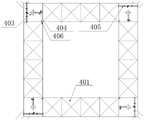
FIG. 4 is a plan view of the upper deck compartments of the lower float of the present invention;
FIG. 5 is a plan view of the lower deck of the lower float of the present invention;
FIG. 6 is a side view of the platform of the present invention;
FIG. 7 is a schematic front view of an IDC module of the present invention;
FIG. 8 is a schematic diagram of a side view configuration of an IDC module of the present invention;
FIG. 9 is a schematic view of the structure of the sea chest of the ballast tank;
FIG. 10 is a schematic view of the structure of the sea pipeline of the cabin;
wherein: 101-floating platform, 102-anchor chain, 103-wind power generator, 104-submarine cable, 105-submarine photoelectric composite cable, 106-onshore substation or centralized control center, 201-GIS switchgear room, 202-main step-up transformer room, 203-transformer cooling equipment, 204-crane, 205-living and office area, 206-helicopter platform, 301-protection and control system room, 302-diesel generator room, 303-mechanical equipment room, 401-ballast tank, 402-first valve, 403-ballast pump, 404-ballast pump pipeline, 405-ballast tank sea pipeline, 406-ventilation pipeline, 407-third valve, 501-cabin, 502-IDC module room, 503-cabin sea pipeline, 504-electric gate valve, 505-electric butterfly valve, 506-ballast pump pipeline, 507-second valve, 601-upper float, 602-lower float, 603-column, 604-drainage pipeline, 607-electrical cable tray, 701-nitrogen supply pipeline, 701-IDC module room base, titanium-equipment cabinet, 705-cooling equipment cabinet, 703-cooling liquid-cooling tank, cooling liquid-cooling tank base, 706-cooling liquid-cooling tank base, and cooling liquid-circulating pump.
Detailed Description
The invention is further explained with reference to the drawings.
As shown in fig. 1, the offshore floating platform integrating the booster station and the data center is close to a wind power plant, communicated with a fan of the wind power plant through a submarine cable, and connected with a land substation or a centralized control center through a submarine photoelectric composite cable. The platform is positioned beside a deep and far sea wind field, and each wind power generator in the wind field transmits electric energy converted from wind energy to the floating platform through a submarine cable. After the electric energy is integrated and boosted on the platform, the electric energy is transmitted to a land transformer substation or a centralized control center through a seabed photoelectric composite cable and then is merged into a power grid for users to use, and the data center and a land base station also exchange data through the seabed photoelectric composite cable.
As shown in fig. 6, there are an upper floating body and a lower floating body, the upper floating body is supported above the lower floating body through a column, the top of the column is located on the lower surface of the upper floating body, the bottom of the column runs through the lower floating body, there are 4 columns in total, and the columns are respectively located at four corners of the platform. The platform is fixed on the sea surface through anchor chains, one end of each anchor chain is connected with the offshore floating platform through a chain stopper, and the other end of each anchor chain is connected with a seabed anchor pile. The platform is close to the wind power plant, the platform is communicated with a fan of the wind power plant through a submarine cable, and the platform is connected with a land substation or a centralized control center through a submarine photoelectric composite cable. The upper floating body is provided with an upper deck and a lower deck, and as shown in fig. 2, a GIS switch equipment room, a main step-up transformer room, transformer cooling equipment, a crane, a living and office area and a helicopter platform are arranged on the upper deck. As shown in fig. 3, the lower deck is provided with a control system room, a diesel generator room, and a mechanical equipment room. GIS switchgear adopts a mechanical spring operating mechanism with high reliability and no maintenance, and is provided with a telescopic joint and an explosion-proof membrane of an air chamber, and insulating gas in the GIS switchgear adopts sulfur hexafluoride. The main step-up transformer is the core equipment of the step-up station and is used for remotely conveying the electric energy after the electric energy is stepped up, so that the electric energy loss in the conveying process is reduced. The main booster transformer is provided with an anti-seismic raft seat so as to ensure that the main booster transformer can still work normally under the shaking of the floating platform. The main step-up transformer is provided with a special cooling device for cooling the main step-up transformer. The indoor monitoring, controlling and communication equipment and the like are arranged in the control system, the working states of the booster station and the data center can be monitored in real time, and the control system can remotely control the actions of various equipment such as a pump, a diesel generator, a valve, a switch and the like, and is a control center of the floating platform. A whole set of diesel engine power generation system is configured in the diesel engine generator room, the diesel engine power generation system does not work at ordinary times, and normal operation of the data center and other equipment is guaranteed through emergency power supply only when the floating platform is in a power loss state due to faults and other reasons. The mechanical equipment room is mainly provided with various mechanical equipment of an air/nitrogen supply system and a fire fighting system.
As shown in fig. 4 and 5, continuous ballast tanks are laid on the lower floating body between adjacent columns to form a ballast tank layer, continuous tanks are laid to form a data center tank layer, the middles of the ballast tank layer and the data center tank layer are hollow, and IDC module tanks are arranged in the tanks of the data center tank layer. When the ballast tank needs to be discharged, the first valve on the pipeline of the ballast pump is opened and the ballast pump is started, so that the seawater ballast can be discharged. When the ballast tank needs to be loaded, a third valve on the sea pipeline of the ballast tank is opened, seawater automatically floods into the ballast tank, and each ballast tank is provided with an independent ventilation pipeline for ventilation during loading and discharging.
Inside the stand, laid ventilative pipeline, nitrogen gas supply pipe way and cat ladder from bottom to top, the nitrogen gas supply pipe way top inserts in the mechanical equipment room, and in the IDC module cabin was inserted to the bottom, ventilative pipeline bottom was inserted in the cabin on data center cabin layer or the ballast cabin on ballast cabin layer, and the top upwards extends through the upper deck. A ballast tank sea pipeline and a cabin sea pipeline are also arranged in the upright column, the ballast tank sea pipeline is positioned in the upright column of the ballast tank layer, one end of the ballast tank sea pipeline is communicated with the data center tank layer, and the other end of the ballast tank sea pipeline is connected into the sea; the cabin sea-going pipeline is positioned in the stand column of the data center cabin layer, one end of the cabin sea-going pipeline is communicated with the data center cabin layer, and the other end of the cabin sea-going pipeline is connected into the sea.
The bottom still is provided with the ballast pump in the stand, and the ballast pump is connected with ballast pump pipeline and drainage line, and in the cabin on ballast pump pipeline access data center cabin layer, drainage line upwards extended, passed lower deck and inserted in the sea in the stand is inside, and the ballast tank on ballast tank layer stretches out and has the drainage branch pipe way to converge to the ballast pump pipeline, is provided with first valve on the drainage branch pipe way, is provided with the second valve on the ballast pump pipeline. The ballast pump and the drainage pipeline are used for discharging ballast water in the ballast tank and the cabin, and different cabins are selected through different valves. When the first valve is opened and the second valve is closed, the seawater in the ballast tank is discharged; when the first valve is closed and the second valve is opened, the seawater in the data center cabin is discharged. The power and signal transmission of all equipment in the lower floating body is transmitted to the upper floating body along the cable tray through cables and optical cables. After the IDC module chamber is overhauled, the nitrogen supply system injects protective nitrogen into the IDC module chamber again through the nitrogen supply pipeline.
As shown in fig. 7 and 8, the IDC module compartment has an IDC module compartment base, the base is an i-steel support frame, seawater is filled between the two i-steel support frames, an IDC module compartment housing is fixed on the IDC module compartment base, a coolant liquid collecting tank is arranged in the IDC module compartment housing and at the bottom of the IDC module compartment housing, coolant is contained in the coolant liquid collecting tank, one row or more than one row of equipment cabinets are fixed in the IDC module compartment housing, each row has a plurality of equipment cabinets, each equipment cabinet has a cooling compartment and a heat exchange coil, a coolant circulating pump is connected to the bottom of the cooling compartment, the top of the cooling compartment is communicated with one end of the heat exchange coil, the other end of the heat exchange coil extends into the coolant liquid collecting tank, and the cooling compartment is located between the equipment cabinet and the IDC module compartment housing. The cooling liquid flows through the cooling cabin and the heat exchange coil, the cooling liquid collecting pool is filled with the cooling liquid in advance, and the IDC module cabin is also internally provided with a cooling liquid expansion cabinet for supplementing the cooling liquid at ordinary times. The seawater between the two I-steel supports is arranged outside the IDC module cabin, and a titanium alloy sheet is separated from the cooling liquid collecting tank, namely the cooling liquid takes away the heat of the equipment cabinet, and then the heat of the cooling liquid of the titanium alloy sheet is transferred to the outside seawater.
The IDC module compartment is a watertight compartment in the form of a cube, the housing of which is made of high cost carbon steel with low thermal conductivity. In order to improve the corrosion resistance of the tank in seawater, the surface of the shell is not only coated with protective paint, but also welded with a zinc block, and the corrosion resistance of the tank is further improved by adopting a sacrificial anode protection method. The IDC module cabin is internally provided with core equipment such as a server and a memory of a data center. In order to achieve better and more energy-saving cooling, the IDC module cabin is placed in seawater for natural cooling at ordinary times, passes through an umbilical cable with a built-in cable and an optical fiber and is connected with a control center of an upper floating body through a stand column, and is connected with a land centralized control center through a seabed photoelectric composite cable, so that data exchange between a seabed data center and the land centralized control center can be achieved. When the IDC module cabin runs for a period of time or needs to be overhauled due to faults, the IDC module cabin is filled with protective nitrogen, air is filled into the IDC module cabin to discharge the nitrogen, then an electric gate valve and an electric butterfly valve on a cabin sea pipeline are closed, and then a ballast pump is started to discharge seawater in the data center cabin through a ballast pump pipeline. Then, a maintainer enters a data center ballast tank layer of a lower floating body through a stand column, and locks an electric gate valve close to the sea side on a sea pipeline of the cabin manually, so that water is fed into the cabin due to misoperation of a sea valve in the maintenance process, and major accidents are avoided. Then, maintenance personnel open the watertight door to enter the data center cabin, open the watertight door on the IDC module cabin and enter for maintenance. After the maintenance is finished, maintenance personnel close watertight doors of the IDC module cabin and the data center cabin, manually unlock the electric gate valve and return to the upper floating body, and then control the nitrogen supply system to refill nitrogen for the maintained IDC module cabin so as to protect equipment cabinets in the IDC module cabin from corrosion and biological invasion. And then the two valves are opened by the electric control of the control room, the seawater enters the data center cabin again to play a cooling role, and meanwhile, the seawater in the ballast cabin is discharged, so that the state of the floating body is kept basically unchanged. Each data center compartment has a separate ventilation line for ventilation during loading and unloading.
The IDC module cabin has three kinds of cooling methods, is provided with temperature sensor in the IDC module cabin, can be according to the cooling method of temperature numerical value automatic selection:
the first mode is natural cooling, when the temperature of the seawater is lower in winter, the heat in the IDC module cabin is conducted to the external seawater only by the cabin wall, namely, the temperature in the unit cabin can be kept to be not higher than a set value T1, and at the moment, no cooling means for consuming energy is needed to be applied, and the natural heat exchange between the cooling cabin and the heat exchange coil and the external cold seawater is needed.
The second mode is circulation cooling in the IDC module cabin, namely, after the temperature in the unit cabin reaches a set value T1, a closed circulation cooling system in the unit cabin is automatically started, so that the speed of taking away heat by cooling liquid is increased, and the temperature in the cabin is reduced. If the temperature is reduced to a set value T0, the cooling system is automatically closed, the first natural cooling mode is returned, and otherwise, the operation of the cooling system is kept.
And the third mode is IDC module cabin external circulation cooling, when the temperature of seawater in summer is higher and the temperature in the IDC module cabin is still raised to T2 when the in-cabin circulation cooling system is in operation, a ballast pump of a floating body positioned under the floating platform is started, a corresponding valve is adjusted, and the seawater in the data center cabin where the IDC module cabin with the higher temperature is located is discharged, so that the external cold seawater automatically floods into the cabin, the external seawater circulates faster to take away the redundant heat, and the temperature in the unit cabin is reduced. The three cooling modes are comprehensively used, so that the cooling energy consumption is saved to the maximum extent, and the operation cost of the data center is reduced.
Claims (10)
1. An offshore floating platform integrating a booster station and a data center is characterized in that: the platform is close to the wind power plant, communicated with a fan of the wind power plant through a submarine cable, and connected with a land substation or a centralized control center through a submarine photoelectric composite cable;
the upper floating body of the platform is supported above the lower floating body through a stand column, the top of the stand column is connected with the lower surface of the upper floating body, the bottom of the stand column penetrates through the lower floating body, the upper floating body is provided with an upper deck and a lower deck, the lower floating body is provided with a ballast tank layer and a data center tank layer, the upper floating body is positioned above the sea surface, the lower floating body is positioned below the sea surface, the upper floating body is provided with an upper deck and a lower deck, the lower floating body is provided with an upper layer and a lower layer, the upper layer is the ballast tank layer, and the lower layer is the data center tank layer;
a GIS switch equipment room, a main step-up transformer room, transformer cooling equipment, a crane, a living and office area and a helicopter platform are arranged on the upper deck, and a control system room, a diesel generator room and a mechanical equipment room are arranged on the lower deck;
continuous ballast compartments are laid between adjacent columns of the lower floating body to form a ballast compartment layer, continuous compartments are laid to form a data center compartment layer, the middles of the ballast compartment layer and the data center compartment layer are hollow, an IDC module compartment is arranged in each compartment of the data center compartment layer, and a temperature sensor is arranged in each IDC module compartment;
a ventilating pipeline, a nitrogen supply pipeline and a ladder stand are laid in the upright column from bottom to top, the top end of the nitrogen supply pipeline is connected into the mechanical equipment chamber, the bottom end of the nitrogen supply pipeline is connected into the IDC module chamber, the bottom end of the ventilating pipeline is connected into a cabin of a data center cabin layer or a ballast cabin of a ballast cabin layer, and the top end of the ventilating pipeline extends upwards through an upper deck;
a ballast tank sea pipeline and a cabin sea pipeline are also arranged in the upright column, the ballast tank sea pipeline is positioned in the upright column of the ballast tank layer, one end of the ballast tank sea pipeline is communicated with the data center tank layer, and the other end of the ballast tank sea pipeline is connected into the sea; the cabin sea-going pipeline is positioned in an upright post of a data center cabin layer, one end of the cabin sea-going pipeline is communicated with the data center cabin layer, and the other end of the cabin sea-going pipeline is connected into the sea;
the bottom in the upright post is also provided with a ballast pump, the ballast pump is connected with a ballast pump pipeline and a drainage pipeline, the ballast pump pipeline is connected into a cabin of a data center cabin layer, the drainage pipeline extends upwards in the upright post and penetrates through a lower deck to be connected into the sea, a ballast tank of the ballast tank layer extends out of a drainage branch pipeline to be converged into the ballast pump pipeline, the drainage branch pipeline is provided with a first valve, and the ballast pump pipeline is provided with a second valve;
the IDC module cabin is provided with an IDC module cabin base, an IDC module cabin shell is fixed on the IDC module cabin base, a cooling liquid collecting pool is arranged in the IDC module cabin shell and at the bottom, cooling liquid is contained in the cooling liquid collecting pool, one row or more than one row of equipment cabinets are fixed in the IDC module cabin shell, each row of equipment cabinets is provided with a plurality of equipment cabinets, each equipment cabinet is provided with a cooling cabin and a heat exchange coil, the bottom of the cooling cabin is connected with a cooling liquid circulating pump, the top of the cooling cabin is communicated with one end of the heat exchange coil, the other end of the heat exchange coil extends into the cooling liquid collecting pool, and the cooling cabin is located between the equipment cabinets and the IDC module cabin shell.
2. The offshore floating platform integrating the booster station and the data center according to claim 1, wherein: the IDC module cabin is a watertight cabin and is made of carbon steel, and the outer surface of the IDC module cabin is coated with protective paint and welded with a zinc block.
3. The offshore floating platform integrating the booster station and the data center according to claim 1 or 2, wherein: the IDC module cabin is connected with the control system room through an umbilical cable of the cable and the optical fiber, and the cable and the umbilical cable of the optical fiber are positioned in the upright post and fixed through an optical cable bracket.
4. The offshore floating platform integrating booster station and data center of claim 1, wherein: the platform is fixed on the sea surface through anchor chains, one end of each anchor chain is connected with the offshore floating platform through a chain stopper, and the other end of each anchor chain is connected with a seabed anchor pile.
5. The offshore floating platform integrating the booster station and the data center according to claim 1, wherein: the cabin sea pipeline is provided with an electric gate valve and an electric butterfly valve, the electric gate valve is arranged at a position close to the seawater position of the cabin sea pipeline, and the electric butterfly valve is arranged at a position far away from the seawater position of the cabin sea pipeline.
6. The offshore floating platform integrating the booster station and the data center according to claim 1, wherein: and a third valve is arranged on the sea pipeline of the ballast tank.
7. The offshore floating platform integrating booster station and data center of claim 1, wherein: an air/nitrogen supply system and a fire fighting system are arranged in the mechanical equipment room, the top end of the nitrogen supply pipeline is connected with the air/nitrogen supply system, and the bottom end of the nitrogen supply pipeline is connected into the IDC module cabin shell.
8. The offshore floating platform integrating the booster station and the data center according to claim 1, wherein: the main booster transformer chamber is internally provided with a cooling device and an anti-seismic raft seat.
9. The offshore floating platform integrating the booster station and the data center according to claim 1, wherein: a base is padded at the bottom of the equipment cabinet in the IDC module cabin shell, and the liquid level in the cooling liquid collecting pool is lower than or equal to the height of the base.
10. The offshore floating platform integrating booster station and data center of claim 1, wherein: the floor of the IDC module bay housing is a titanium alloy sheet.
Priority Applications (1)
| Application Number | Priority Date | Filing Date | Title |
|---|---|---|---|
| CN202211036853.1A CN115339580A (en) | 2022-08-29 | 2022-08-29 | Offshore floating platform integrating booster station and data center |
Applications Claiming Priority (1)
| Application Number | Priority Date | Filing Date | Title |
|---|---|---|---|
| CN202211036853.1A CN115339580A (en) | 2022-08-29 | 2022-08-29 | Offshore floating platform integrating booster station and data center |
Publications (1)
| Publication Number | Publication Date |
|---|---|
| CN115339580A true CN115339580A (en) | 2022-11-15 |
Family
ID=83954430
Family Applications (1)
| Application Number | Title | Priority Date | Filing Date |
|---|---|---|---|
| CN202211036853.1A Pending CN115339580A (en) | 2022-08-29 | 2022-08-29 | Offshore floating platform integrating booster station and data center |
Country Status (1)
| Country | Link |
|---|---|
| CN (1) | CN115339580A (en) |
Cited By (1)
| Publication number | Priority date | Publication date | Assignee | Title |
|---|---|---|---|---|
| GB2623749A (en) * | 2022-10-21 | 2024-05-01 | Aker Solutions As | Floating electricity distribution |
-
2022
- 2022-08-29 CN CN202211036853.1A patent/CN115339580A/en active Pending
Cited By (1)
| Publication number | Priority date | Publication date | Assignee | Title |
|---|---|---|---|---|
| GB2623749A (en) * | 2022-10-21 | 2024-05-01 | Aker Solutions As | Floating electricity distribution |
Similar Documents
| Publication | Publication Date | Title |
|---|---|---|
| CN105673329B (en) | Ship wind-light storage wave energy comprehensively utilizes power generator | |
| RU2549362C2 (en) | Subsea module for production of electric energy | |
| CN102195334A (en) | Method and system for improving reliability of emergency power supplies of nuclear power plant | |
| CN113216710B (en) | Seabed big data center suitable for built offshore wind power plant and construction method | |
| US8866315B2 (en) | Underwater electricity generation module provided with a base | |
| CN115339580A (en) | Offshore floating platform integrating booster station and data center | |
| CN208683061U (en) | Offshore service ship comprehensive tower ladder system | |
| CN110042819A (en) | A kind of marine converter station for flexible HVDC transmission system | |
| CN203826014U (en) | Semi-submersible platform floating nuclear power station | |
| CN111232143A (en) | Showy formula intelligence leisure platform on water | |
| CN203158199U (en) | Floating type fan foundation | |
| CN112448080A (en) | Immersive energy storage box and immersive energy storage system | |
| JPS629722B2 (en) | ||
| RU2608843C1 (en) | Underwater electricity production module | |
| CN206131335U (en) | Marine nuclear energy facility master control room can system of residing | |
| AU2019337365B2 (en) | Modular floating data centre park | |
| CN114212199A (en) | Movable semi-submersible floating type offshore super computing center | |
| CN210007231U (en) | modular offshore converter station structure | |
| CN102588200A (en) | Static water power generation system | |
| CN220493298U (en) | Be applied to external dilatation formula data center under water | |
| CN220383405U (en) | Be applied to horizontal platform formula data center | |
| CN216185945U (en) | Seabed big data center suitable for built offshore wind power plant | |
| CN113503070A (en) | Modular offshore booster station and installation method thereof | |
| CN217011375U (en) | Cabin structure and underwater data center with same | |
| CN213125354U (en) | Modular offshore booster station |
Legal Events
| Date | Code | Title | Description |
|---|---|---|---|
| PB01 | Publication | ||
| PB01 | Publication | ||
| SE01 | Entry into force of request for substantive examination | ||
| SE01 | Entry into force of request for substantive examination |