CN115338642A - Fixed frock is used in drilling of door and window angle sign indicating number and tapping - Google Patents
Fixed frock is used in drilling of door and window angle sign indicating number and tapping Download PDFInfo
- Publication number
- CN115338642A CN115338642A CN202211276267.4A CN202211276267A CN115338642A CN 115338642 A CN115338642 A CN 115338642A CN 202211276267 A CN202211276267 A CN 202211276267A CN 115338642 A CN115338642 A CN 115338642A
- Authority
- CN
- China
- Prior art keywords
- magnetic block
- magnetic
- tapping
- rotary table
- door
- Prior art date
- Legal status (The legal status is an assumption and is not a legal conclusion. Google has not performed a legal analysis and makes no representation as to the accuracy of the status listed.)
- Granted
Links
Images


Classifications
-
- B—PERFORMING OPERATIONS; TRANSPORTING
- B23—MACHINE TOOLS; METAL-WORKING NOT OTHERWISE PROVIDED FOR
- B23P—METAL-WORKING NOT OTHERWISE PROVIDED FOR; COMBINED OPERATIONS; UNIVERSAL MACHINE TOOLS
- B23P23/00—Machines or arrangements of machines for performing specified combinations of different metal-working operations not covered by a single other subclass
- B23P23/02—Machine tools for performing different machining operations
-
- B—PERFORMING OPERATIONS; TRANSPORTING
- B23—MACHINE TOOLS; METAL-WORKING NOT OTHERWISE PROVIDED FOR
- B23Q—DETAILS, COMPONENTS, OR ACCESSORIES FOR MACHINE TOOLS, e.g. ARRANGEMENTS FOR COPYING OR CONTROLLING; MACHINE TOOLS IN GENERAL CHARACTERISED BY THE CONSTRUCTION OF PARTICULAR DETAILS OR COMPONENTS; COMBINATIONS OR ASSOCIATIONS OF METAL-WORKING MACHINES, NOT DIRECTED TO A PARTICULAR RESULT
- B23Q1/00—Members which are comprised in the general build-up of a form of machine, particularly relatively large fixed members
- B23Q1/25—Movable or adjustable work or tool supports
- B23Q1/64—Movable or adjustable work or tool supports characterised by the purpose of the movement
- B23Q1/66—Worktables interchangeably movable into operating positions
-
- B—PERFORMING OPERATIONS; TRANSPORTING
- B23—MACHINE TOOLS; METAL-WORKING NOT OTHERWISE PROVIDED FOR
- B23Q—DETAILS, COMPONENTS, OR ACCESSORIES FOR MACHINE TOOLS, e.g. ARRANGEMENTS FOR COPYING OR CONTROLLING; MACHINE TOOLS IN GENERAL CHARACTERISED BY THE CONSTRUCTION OF PARTICULAR DETAILS OR COMPONENTS; COMBINATIONS OR ASSOCIATIONS OF METAL-WORKING MACHINES, NOT DIRECTED TO A PARTICULAR RESULT
- B23Q3/00—Devices holding, supporting, or positioning work or tools, of a kind normally removable from the machine
- B23Q3/02—Devices holding, supporting, or positioning work or tools, of a kind normally removable from the machine for mounting on a work-table, tool-slide, or analogous part
- B23Q3/06—Work-clamping means
- B23Q3/062—Work-clamping means adapted for holding workpieces having a special form or being made from a special material
Abstract
The invention relates to the technical field of door and window accessory processing, and provides a fixing tool for drilling and tapping door and window corner codes, which comprises a base, a rotary table and clamping mechanisms, wherein the rotary table is rotatably connected to a mandrel arranged in the middle of the base; the upper end of the mandrel is a regular prism, and a first magnetic block and a second magnetic block with different magnetic poles are respectively arranged on two opposite side surfaces of the regular prism; each clamping mechanism is provided with a pair of movable clamps and a connecting rod connected with the movable clamps, and one end of the connecting rod, which is close to the regular prism, is provided with a fifth magnetic block with the same magnetic pole as the second magnetic block; when the fifth magnetic block is aligned with the first magnetic block, the movable clamp is opened to release the corner connector; when the fifth magnetic block and the second magnetic block are in positive alignment, the movable clamp is closed to clamp the corner connector. Through the rotation of the rotary table, the two sets of clamping mechanisms can be opened and closed respectively under the magnetic action of the first magnetic block and the second magnetic block, so that stations are exchanged, the purposes of simultaneous processing and feeding and discharging are achieved, and the processing efficiency of the corner connectors is improved.
Description
Technical Field
The invention relates to the technical field of door and window accessory machining, in particular to a fixing tool for drilling and tapping door and window corner connectors.
Background
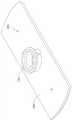
In the manufacturing process of doors and windows, corner connectors play a very important role, and are mainly used as hardware for connecting right-angle intersecting members of doors and windows and generally used in decoration engineering and furniture assembly. For example, aluminum corner connectors are mainly adopted in aluminum alloy doors and windows, and compared with other materials, the aluminum material has the advantages of good heat shrinkage, hardness and the like, and has high stability after being connected; after the door and window is provided with the aluminum corner connectors, the regularity of the corner splicing gaps is greatly improved, and the service life of the door and window can be prolonged.
At present, the processing of angle sign indicating number mainly adopts semi-automatic or semi-mechanical processing mode, and its clamping is fixed in on drilling and tapping all-in-one after through drilling or drilling tapping process such as processing procedure again, just can process the through-hole or the screw hole that needs in its both sides limit. However, due to the unique right-angle structure of the corner connector, the process of clamping the corner connector by the existing tool is very complicated, so that loading and unloading are inconvenient, the fixed station is single, and unloading cannot be simultaneously carried out during machining, so that the machining efficiency is influenced; in addition, the existing tool is poor in structural stability, the through holes or threaded holes machined by drilling and tapping on two sides of the angle code are large in position tolerance and low in precision, and later-stage installation and use are not facilitated.
Disclosure of Invention
Aiming at the defects of the prior art, the invention provides a fixing tool for drilling and tapping door and window corner connectors, and aims to solve the problems that the process of clamping the corner connectors by the existing tool is very complicated, the loading and unloading are inconvenient, the fixing station is single, the simultaneous loading and unloading can not be carried out during processing, and the processing efficiency is influenced.
In order to achieve the purpose, the invention provides the following technical scheme:
the utility model provides a door and window angle sign indicating number drilling and tapping are with fixed frock, includes:
the base is connected to the drilling and tapping integrated machine;
the rotary table is rotatably connected to a mandrel arranged in the middle of the base; and
two sets of clamping mechanisms are arranged symmetrically to the mandrel and fixedly connected to the top surface of the rotary table;
the upper end of the mandrel is a regular prism, and two opposite side surfaces of the regular prism are respectively provided with a first magnetic block and a second magnetic block with different magnetic poles; each clamping mechanism is provided with a pair of movable clamps and a connecting rod connected with the movable clamps, and a fifth magnetic block with the same magnetic pole as the second magnetic block is arranged at one end of the connecting rod close to the regular prism; when the fifth magnetic block is aligned with the first magnetic block, the movable clamp is opened to release the corner code; when the fifth magnetic block and the second magnetic block are in positive alignment, the movable clamp is closed to clamp the corner connector.
In one embodiment disclosed in the present application, the clamping mechanism includes a fixing clamp, a plurality of pins are disposed on a side surface of the fixing clamp, and the pins are connected with a plurality of sleeves disposed on a top surface of the turntable in an inserting manner;
the U-shaped structure of the fixing clamp is adopted, one end of the fixing clamp, which is far away from the mandrel, is provided with a notch, the parts of the fixing clamp, which are positioned at the two sides of the notch, are drawn together towards the middle to form an inclined arm which is distributed in an internal splayed shape, and a through cross-shaped sliding groove is formed in the inclined arm along the length direction of the inclined arm;
the same sides of the two ends of the movable clamp are respectively provided with an inclined back surface, the inclined back surface at one end is provided with a T-shaped strip which is in sliding connection with the cross sliding chute, and the inclined back surface at the other end is provided with a guide hole which penetrates through the front surface of the movable clamp;
the connecting rod comprises a first guide rod and a second guide rod which are mutually perpendicular and connected to form a T-shaped structure, one end, far away from the second guide rod, of the first guide rod penetrates through a through hole formed in the bottom in the fixing clamp in a sliding mode and then is fixedly connected with the fifth magnetic block, and the second guide rod penetrates through the guide hole in a sliding mode and then extends into the cross-shaped sliding groove.
In one embodiment disclosed in the application, the movable clamp is provided with an upper convex block and a lower convex block at the rear part of the front surface for clamping the corner connectors;
a gap is reserved between the upper convex block and the lower convex block to form a clamping groove for clamping the corner connector;
the front end of the lower protruding block is obliquely arranged to enlarge the inlet of the clamping groove.
In one embodiment disclosed herein, the clamping mechanism further comprises a compression spring;
the pressure spring is sleeved on the first guide rod, and two ends of the pressure spring are respectively connected with the second guide rod and the bottom in the fixing clamp in an abutting mode.
In one embodiment disclosed in the present application, the top surface of the rotary table is provided with a U-shaped pre-insertion groove;
the pre-inserting slot is located below the notch and used for placing an angle code to achieve pre-fixing.
In one embodiment disclosed in the application, two side faces of the regular prism, which are close to the side face where the first magnetic block is located, are provided with a third magnetic block, and the magnetic poles of the third magnetic block and the first magnetic block are the same;
the two side faces of the regular prism, which are close to the side face where the second magnetic block is located, are provided with fourth magnetic blocks, and the magnetic poles of the fourth magnetic blocks are the same as those of the second magnetic blocks;
the first magnetic block and the second magnetic block are equal in size and larger, and the third magnetic block and the fourth magnetic block are equal in size and smaller.
In one embodiment disclosed in the present application, the regular prism is an eight-square prism, and the first to fifth magnetic blocks are all neodymium iron boron magnets.
In one embodiment of the present disclosure, the turntable is horizontally rotated at an angle of 180 °/time by the driving of the positioning assembly.
In one embodiment of the present disclosure, the positioning assembly includes a servo motor, a pinion gear, a bull gear, and a positioning sensor;
the servo motor and the positioning sensor are fixedly arranged on the base and are electrically connected with each other, the small gear is fixedly connected to the output end of the servo motor and is meshed with the large gear, and the large gear is fixedly connected with a shaft sleeve arranged in the middle of the rotary table;
4 positioning sensors are uniformly distributed around the circumference of the mandrel, wherein 2 positioning sensors are respectively aligned with the first magnetic block and the second magnetic block;
the bottom surface of the rotary table is symmetrically provided with a pair of induction blocks corresponding to the shaft sleeve, and the induction blocks can be aligned with the positioning sensor through the horizontal rotation of the rotary table;
the spindle is sleeved with a pair of thrust ball bearings, and the thrust ball bearings are respectively embedded in sinking areas at two ends of the spindle sleeve.
In one embodiment of the present disclosure, the positioning assembly further comprises a lifting support electrically connected to the positioning sensor;
the lifting support is fixedly connected to the top surface of the base and is symmetrically provided with two parts in the direction of the mandrel, and the two lifting supports are respectively aligned with the first magnetic block and the second magnetic block and used for supporting the rotary table to reduce the shaking of the rotary table.
Compared with the prior art, the invention has the beneficial effects that:
1. through the rotation of the rotary table, the two sets of clamping mechanisms can be opened and closed respectively under the magnetic action of the first magnetic block and the second magnetic block with different magnetic poles, so that stations are exchanged, the purpose that processing and feeding and discharging can be carried out simultaneously is achieved, and the processing efficiency of the angle code is improved.
2. The angle connector is clamped through the clamping groove, the movable clamp is better attached to the angle connector, the stability of the fixed tool can be improved, and therefore the position accuracy of a through hole or a threaded hole machined by the angle connector is guaranteed.
3. In the horizontal rotation process of the rotary table, when the fifth magnetic block is not opposite to the first magnetic block and the second magnetic block and is completely separated from the magnetic force action range, the second guide rod can enable the movable clamp to be in a half-open and half-closed state through the reset force action of the pressure spring so as to pre-clamp the angle code, and the shaking caused by the rotation of the rotary table is reduced; meanwhile, when the fifth magnetic block and the second magnetic block are in positive alignment, repulsive force between the fifth magnetic block and the second magnetic block and resetting force of the pressure spring are superposed, clamping force of the diagonal brace can be enhanced, stability of the fixing tool is further improved, and position accuracy of a through hole or a threaded hole machined by the diagonal brace is guaranteed.
4. When the clamping, the angle sign indicating number can insert earlier and realize fixing in advance in the slot, later by the activity clamp tight, when saving the clamping of angle sign indicating number and using, is favorable to the improvement of angle sign indicating number machining efficiency, the slot can reduce rocking of angle sign indicating number in advance simultaneously, guarantees its stability in drilling tapping course of working.
5. Along with the horizontal rotation of the rotary table, attractive force (repulsive force) borne by the fifth magnetic block is changed from strong to weak, so that the clamping force of the corner connector is controlled, and the stability of the corner connector in the processes of loading and unloading and drilling and tapping is improved.
6. The supporting top is supported on the bottom surface of the rotary table to reduce shaking, so that the stability of the angle code in the processes of loading and unloading and drilling and tapping can be improved again, and the position accuracy of a through hole or a threaded hole machined by the angle code is guaranteed.
Drawings
In order to more clearly illustrate the embodiments of the present application or the technical solutions in the prior art, the drawings used in the description of the embodiments or the prior art will be briefly described below, and it is obvious that the drawings in the following description are only some embodiments of the present application, and for those skilled in the art, other drawings can be obtained according to these drawings without creative efforts.
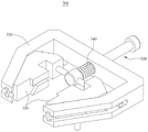
FIG. 1 is a schematic perspective view of the present invention;
FIG. 2 is a schematic top view of the present invention;
FIG. 3 isbase:Sub>A schematic sectional view taken along line A-A in FIG. 2;
FIG. 4 is a schematic perspective view of the present invention with the turntable and clamping mechanism hidden;
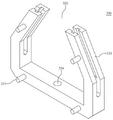
FIG. 5 is a schematic perspective view of the turntable;
fig. 6 is a schematic perspective view of the turntable at another angle;
FIG. 7 is a perspective view of the clamping mechanism;
FIG. 8 is a perspective view of the retaining clip;
FIG. 9 is a perspective view of the clip;
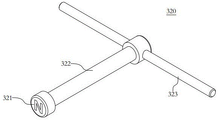
fig. 10 is a perspective view of the connecting rod.
The reference numerals are illustrated below:
100. the magnetic bearing comprises a base, 110, a mandrel, 111, a first magnetic block, 112, a second magnetic block, 113, a third magnetic block, 114, a fourth magnetic block, 120 and a thrust ball bearing;
200. the rotary table comprises a rotary table 210, a sleeve 220, a pre-inserting groove 230, a shaft sleeve 240 and an induction block;
300. the clamping mechanism comprises a clamping mechanism 310, a movable clamp 311, a T-shaped strip 312, a guide hole 313, an upper convex block 314, a lower convex block 320, a connecting rod 321, a fifth magnetic block 322, a first guide rod 323, a second guide rod 330, a fixing clamp 331, a pin shaft 332, a notch 333, an inclined arm 334, a through hole 340 and a pressure spring;
400. the device comprises a positioning component 410, a servo motor 420, a pinion gear 430, a bull gear 440, a positioning sensor 450, a lifting support 451, a lifting oil cylinder 452 and a supporting plate.
Detailed Description
In the following, only certain exemplary embodiments are briefly described. As those skilled in the art would realize, the described embodiments may be modified in various different ways, all without departing from the spirit or scope of the present invention. Accordingly, the drawings and description are to be regarded as illustrative in nature, and not as restrictive.
In the description of the present invention, it is to be understood that the terms "central," "longitudinal," "lateral," "upper," "lower," "front," "rear," "left," "right," "vertical," "horizontal," "top," "bottom," "inner," "outer," "clockwise," "counterclockwise," "axial," "radial," "circumferential," and the like are used in the orientations and positional relationships indicated in the drawings for convenience in describing and simplifying the description, and are not intended to indicate or imply that the device or element so referred to must have a particular orientation, be constructed and operated in a particular orientation, and are therefore not to be considered as limiting the invention.
Furthermore, the terms "first", "second" and "first" are used for descriptive purposes only and are not to be construed as indicating or implying relative importance or to implicitly indicate the number of technical features indicated. Thus, a feature defined as "first" or "second" may explicitly or implicitly include one or more of that feature. In the description of the present invention, "a plurality" means two or more unless specifically defined otherwise.
In the present invention, unless otherwise expressly stated or limited, the terms "mounted," "connected," "secured," and the like are to be construed broadly and can, for example, be fixedly connected, detachably connected, or integrally formed; the connection can be mechanical connection, electrical connection or communication; either directly or indirectly through intervening media, either internally or in any other relationship. The specific meanings of the above terms in the present invention can be understood according to specific situations by those of ordinary skill in the art.
In the present invention, unless otherwise expressly stated or limited, "above" or "below" a first feature means that the first and second features are in direct contact, or that the first and second features are not in direct contact but are in contact with each other via another feature therebetween. Also, the first feature being "on," "above" and "over" the second feature includes the first feature being directly on and obliquely above the second feature, or merely indicating that the first feature is at a higher level than the second feature. A first feature being "under," "below," and "beneath" a second feature includes the first feature being directly under and obliquely below the second feature, or simply meaning that the first feature is at a lesser elevation than the second feature.
The following disclosure provides many different embodiments or examples for implementing different features of the invention. To simplify the disclosure of the present invention, specific example components and arrangements are described below. Of course, they are merely examples and are not intended to limit the present invention.
Embodiments of the present invention will be described in detail below with reference to the accompanying drawings.
Referring to fig. 1 to 10, the present invention provides a fixing tool for drilling and tapping a door and window corner connector, including:
a base 100 connected to a drilling and tapping machine (not shown);
a turntable 200 rotatably connected to the spindle 110 provided in the middle of the base 100; and
two sets of clamping mechanisms 300 are arranged symmetrically to the mandrel 110 and fixedly connected to the top surface of the turntable 200;
the upper end of the mandrel 110 is a regular prism, and two opposite side surfaces of the regular prism are respectively provided with a first magnetic block 111 and a second magnetic block 112 with different magnetic poles; each set of clamping mechanism 300 is provided with a pair of movable clamps 310 and a connecting rod 320 connected with the movable clamps, and one end of the connecting rod 320 close to the regular prism is provided with a fifth magnetic block 321 with the same magnetic pole as the second magnetic block 112; when the fifth magnetic block 321 is aligned with the first magnetic block 111, the movable clamp 310 is opened to release the corner connector, so that loading and unloading of the corner connector are realized; when the fifth magnetic block 321 is aligned with the second magnetic block 112, the movable clamp 310 is closed to clamp the corner connector, so that the drilling and tapping of the corner connector are realized.
Specifically, the two sets of gripping mechanisms 300 constitute two stations (loading and unloading station and processing station) spaced 180 ° apart in the horizontal plane, which rotate synchronously with the turntable 200. In operation, when the turntable 200 rotates on the spindle 110 to enable the fifth magnetic block 321 of one set of the clamping mechanism 300 to face the first magnetic block 111, due to the fact that the magnetic poles of the fifth magnetic block are different from those of the first magnetic block 111 and attract each other, the connecting rod 320 is drawn by magnetic force to approach the first magnetic block 111 and open the corresponding pair of movable clamps 310, and at the moment, an angle code to be drilled and tapped is placed between the pair of movable clamps 310 to complete feeding; the fifth magnetic block 321 of the other set of clamping mechanism 300 is just opposite to the second magnetic block 112, and due to the same magnetic poles, the fifth magnetic block and the second magnetic block are mutually repelled, and the connecting rod 320 is far away from the second magnetic block 112 under the action of magnetic repulsion and closes the corresponding pair of movable clamps 310; then, the turntable 200 horizontally rotates 180 degrees, so that the two stations are interchanged, the fifth magnetic block 321 of the previous set of clamping mechanism 300 is separated from the attraction range of the first magnetic block 111 and enters the repulsion range of the second magnetic block 112 until the fifth magnetic block is opposite to the second magnetic block 112, and the pair of movable clamps 310 with the corner codes placed therebetween are closed under the repulsion action of magnetic force so as to clamp the corner codes, so that the corner codes are drilled and tapped by a tool bit of the drilling and tapping all-in-one machine; meanwhile, the fifth magnetic block 321 of another previous set of clamping mechanism 300 is separated from the repulsive force range of the second magnetic block 112 and enters the attractive force range of the first magnetic block 111 until the attractive force range of the first magnetic block 111 is opposite to the first magnetic block 111, and at this time, the corresponding pair of movable clamps 310 are opened for second feeding of corner connectors; after the drilling and tapping of the previous corner brace is finished, the rotary table 200 horizontally rotates 180 degrees again, so that the two stations are exchanged for the second time, the second corner brace is clamped to enter the machining station, the previous corner brace is loosened to return to the loading and unloading station, the corner brace is taken down, a new corner brace is placed at the same time to finish blanking and loading, and then continuous machining operation is carried out according to the operation. That is, through the rotation of the turntable 200, the two sets of clamping mechanisms 300 can be opened and closed respectively under the magnetic force action of the first and second magnetic blocks with different magnetic poles, so that stations are exchanged, the purpose of simultaneously performing machining and loading and unloading is achieved, and the machining efficiency of the corner connector is improved.
The clamping mechanism 300 comprises a fixing clamp 330, a plurality of pin shafts 331 (shown in detail in fig. 8) are arranged on the side surface of the fixing clamp 330, and the pin shafts 331 are in plug connection with a plurality of sleeves 210 (shown in detail in fig. 5) arranged on the top surface of the rotary table 200, so that the fixing clamp 330 is suspended and is not attached to the top surface of the rotary table 200, and the feeding of a tool bit during the angle code drilling and tapping process is facilitated; the fixing clip 330 is u-shaped, one end of the fixing clip far away from the mandrel 110 is provided with a notch 332, the parts of the fixing clip 330 at the two sides of the notch 332 are closed to the middle to form inclined arms 333 which are distributed in an inner splay shape, and a through cross-shaped sliding groove is arranged in the inclined arms 333 along the length direction; the two ends of the movable clamp 310 are provided with an inclined back surface (shown in detail in fig. 9) on the same side, one end of the inclined back surface is provided with a T-shaped strip 311 connected with the cross sliding groove in a sliding manner, and the other end of the inclined back surface is provided with a guide hole 312 penetrating through the front surface of the movable clamp 310; the connecting rod 320 includes a first guide rod 322 and a second guide rod 323 (shown in detail in fig. 10) which are connected to each other perpendicularly and form a T-shaped structure, one end of the first guide rod 322, which is far away from the second guide rod 323, slides through a through hole 334 formed in the bottom of the fixing clip 330 and then is fixedly connected to the fifth magnet 321, and the second guide rod 323, which slides through the guide hole 312, extends into the cross sliding slot. Specifically, by the horizontal rotation of the turntable 200, the fifth magnetic block 321 of one set of clamping mechanism 300 faces the first magnetic block 111, and the first magnetic block 321 and the first magnetic block 111 are opposite to each other, and the magnetic poles of the first magnetic block and the first magnetic block are different and mutually attracted, so that the first guide rod 322 is driven to slide in the through hole 334, so that the distance between the fifth magnetic block 321 and the first magnetic block 111 is gradually reduced (but not attracted together, that is, a gap is formed at the end), meanwhile, the second guide rod 323 follows the first guide rod 322 and drives the movable clamp 310 to slide in the cross chute through the guide hole 312 so as to be accommodated in the gap 332, so that the pair of movable clamps 310 is opened to facilitate the placement of the angle code, and then after the turntable 200 rotates by 180 ° in the horizontal plane, the fifth magnetic block 321 faces the second magnetic block 112, and the first guide rod 322 slides reversely along the through hole 334 under the repulsive force so that the distance between the fifth magnetic block 321 and the second magnetic block 112 is gradually increased, and the second guide rod 323 follows the first guide rod 322 and drives the movable clamp 310 to reversely slide in the cross chute 312 so as to extend out of the gap 332, thereby clamping the previously placed angle code; and the opening and closing actions of the other clamping mechanism 300 are just opposite, so that station exchange is realized under the condition that the rotary table 200 rotates, and the simultaneous processing, loading and unloading can be ensured.
Referring to fig. 9, in order to adapt to a specific right-angle structure of the corner connector, an upper protrusion 313 and a lower protrusion 314 are arranged at the rear of the front of the movable clamp 310 for clamping the corner connector, a gap is left between the upper protrusion 313 and the lower protrusion 314 to form a slot for clamping the corner connector, and the front end (the end far away from the guide hole 312) of the lower protrusion 314 is obliquely arranged to increase the entrance of the slot, so that the corner connector can be conveniently clamped. That is to say, hold the angle sign indicating number through the draw-in groove card, the laminating is better between activity clamp 310 and the angle sign indicating number, can improve the stability of this fixed frock to guarantee the position accuracy of the through-hole or the screw hole that the angle sign indicating number was processed out.
Referring to fig. 7, the clamping mechanism 300 further includes a compression spring 340, the compression spring 340 is sleeved on the first guide rod 322, and two ends of the compression spring 340 are respectively connected with the second guide rod 323 and the bottom of the fixing clip 330 in an abutting manner. In the horizontal rotation process of the rotary table 200, when the fifth magnetic block 321 is not opposite to the first magnetic block 111 and the second magnetic block 112 and is completely separated from the magnetic action range, the second guide rod 323 enables the movable clamp 310 to be in a half-open and half-closed state through the reset force action of the pressure spring 340, so that the corner codes are pre-clamped, and the shaking caused by the rotation of the rotary table 200 is reduced; meanwhile, when the fifth magnetic block 321 and the second magnetic block 112 are aligned, repulsive force between the fifth magnetic block 321 and the second magnetic block is superposed with reset force of the pressure spring 340, so that clamping force of the diagonal brace can be enhanced, stability of the fixing tool is further improved, and position accuracy of a through hole or a threaded hole machined by the diagonal brace is guaranteed.
Referring to fig. 2 and 5, the top surface of the rotary table 200 is provided with a u-shaped pre-insertion slot 220, and the pre-insertion slot 220 is located below the notch 332 for placing an angle to achieve pre-fixing. During the clamping, the angle sign indicating number can insert earlier and realize fixing in advance in slot 220, later presss from both sides tightly by activity clamp 310 clamp, when saving the angle sign indicating number clamping usefulness, is favorable to the improvement of angle sign indicating number machining efficiency, and slot 220 can reduce rocking of angle sign indicating number in advance simultaneously, guarantees its stability in drilling tapping course of working.
Referring to fig. 2, two side faces of the regular prism adjacent to the side face where the first magnetic block 111 is located are provided with third magnetic blocks 113, and the magnetic poles of the third magnetic blocks 113 are the same as those of the first magnetic blocks 111; the two side faces of the regular prism, which are close to the side face where the second magnetic block 112 is located, are provided with fourth magnetic blocks 114, and the magnetic poles of the fourth magnetic blocks 114 are the same as those of the second magnetic block 112; the first magnetic block 111 and the second magnetic block 112 are equal in size and large in size, and have strong magnetic force; the third magnetic block 113 and the fourth magnetic block 114 have the same volume and are smaller, and the magnetic force is weaker. When the fifth magnetic block 321 and the first magnetic block 111 (the second magnetic block 112) are in positive pairing, the attractive force (repulsive force) between the fifth magnetic block 321 and the first magnetic block 111 (the second magnetic block 112) is strongest, then along with the horizontal rotation of the turntable 200, the fifth magnetic block 321 gradually departs from the range of stronger attractive force (repulsive force) of the first magnetic block 111 (the second magnetic block 112) and enters the range of weaker attractive force (repulsive force) of the third magnetic block 113 (the fourth magnetic block 114), at this time, the reset force of the compression spring 340 gradually plays a main role to pre-clamp the corner code, and finally, when the fifth magnetic block 321 leaves the range of attractive force (repulsive force) of the third magnetic block 113 (the fourth magnetic block 114), the clamping of the corner code is completely realized by the reset force of the compression spring 340. That is, along with the horizontal rotation of the turntable 200, the attraction (repulsive force) applied to the fifth magnetic block 321 is changed from strong to weak to zero, so that the clamping force of the corner brace is controlled, and the stability of the corner brace in the processes of loading and unloading and drilling and tapping is improved.
In this embodiment, the regular prism is a regular octagonal prism, and the first to fifth magnetic blocks are all neodymium iron boron magnets. The turntable 200 horizontally rotates 45 degrees, and the fifth magnetic block 321 is changed from a state of being opposite to the first magnetic block 111 (the second magnetic block 112) to a state of being opposite to the third magnetic block 113 (the fourth magnetic block 114); the turntable 200 rotates horizontally by 90 °, the fifth magnet 321 is not affected by magnetic force at all, and the restoring force of the compression spring 340 plays a major role at this time. Neodymium iron boron magnet magnetic force is strong, can effectively guarantee the magnetic force effect between first to the fifth magnetic path to improve the stability of this fixed frock once more. Specifically, in the manufacturing process, as shown in fig. 4 and 10, the magnetic poles of the first magnetic block 111 and the third magnetic block 113 can be manufactured into S-level, and the magnetic poles of the second magnetic block 112, the fourth magnetic block 114 and the fifth magnetic block 321 can be manufactured into N-level; alternatively, their poles are all reversed.
Referring to fig. 1 to 4, the turn table 200 is horizontally rotated at an angle of 180/rotation by the driving of the positioning assembly 400. Specifically, the positioning assembly 400 includes a servo motor 410, a pinion 420, a gearwheel 430 and a positioning sensor 440, the servo motor 410 and the positioning sensor 440 are both fixedly mounted on the base 100 and electrically connected to each other, the pinion 420 is fixedly connected to an output end of the servo motor 410 and is engaged with the gearwheel 430, and the gearwheel 430 is fixedly connected (specifically, connected by a flat key) to the shaft sleeve 230 disposed in the middle of the turntable 200; the positioning sensors 440 are uniformly distributed with 4 (i.e. spaced by 90 °) around the circumference of the spindle 110, wherein 2 of the positioning sensors are respectively aligned with the first magnetic block 111 and the second magnetic block 112 (i.e. located on the same straight line); referring to fig. 6, the bottom surface of the turntable 200 is provided with a pair of sensing blocks 240 symmetrically to the shaft housing 230, and the sensing blocks 240 can be aligned with the position sensor 440 by the horizontal rotation of the turntable 200; the spindle 110 is sleeved with a pair of thrust ball bearings 120, and the thrust ball bearings 120 are respectively embedded in the sinking regions at two ends of the sleeve 230 (i.e. the turntable 200 is rotatably connected with the spindle 110 through the thrust ball bearings 120). The servo motor 410 is started to drive the pinion 420 to rotate so as to drive the bull gear 430 to rotate, and the shaft sleeve 230 rotates along with the pinion, so that the horizontal rotation of the rotary table 200 is realized; when the sensing block 240 is aligned with the positioning sensor 440 and the positioning sensor 440 belongs to one of the first magnetic block 111 and the second magnetic block 112, the servo motor 410 is stopped, and at this time, the fifth magnetic block 321 is just opposite to the first magnetic block 111 and the second magnetic block 112, so that the positioning of the turntable 200 is realized; when the turntable 200 continues to rotate horizontally by 90 °, the sensing block 240 is aligned with the other positioning sensor 440, and the stationary state of the horizontal rotation of the turntable 200 can be detected according to the signal of the positioning sensor 440, so as to prevent danger. In the present embodiment, the small gear 420 and the large gear 430 are both spur gears.
Referring to fig. 4, the positioning assembly 400 further includes a lifting support 450 electrically connected to the positioning sensor 440, the lifting support 450 is fixedly connected to the top surface of the base 100 and has two pieces symmetrical to the core shaft 110, and the two pieces of lifting support 450 are respectively aligned with (i.e. in the same line with) the first magnetic block 111 and the second magnetic block 112 for supporting the turntable 200 to reduce the wobbling. Specifically, the elevating support 450 includes an elevating cylinder 451 and a support plate 452 connected to a working end thereof. When the servo motor 410 drives the rotary table 200 to horizontally rotate, the induction block 240 is aligned with the positioning sensor 440 on the same straight line with the first magnetic block 111 and the second magnetic block 112, the servo motor 410 stops, at the moment, the fifth magnetic block 321 is aligned with the first magnetic block 111 and the second magnetic block 112, the lifting oil cylinder 451 is started, the working end of the lifting oil cylinder 451 extends upwards, the supporting plate 452 is driven to abut against the bottom surface of the rotary table 200 to support the rotary table 200 so as to reduce shaking, the stability of loading and unloading of corner connectors and the stability of a drilling and tapping process can be improved again, and the position accuracy of through holes or threaded holes machined by the corner connectors is guaranteed.
The above embodiments are only preferred embodiments of the present invention, and are not intended to limit the technical solutions of the present invention, so long as the technical solutions can be realized on the basis of the above embodiments without creative efforts, and should be considered to fall within the protection scope of the patent claims of the present invention.
Claims (10)
1. The utility model provides a door and window angle sign indicating number drilling and tapping are with fixed frock, a serial communication port, include:
the base is connected to the drilling and tapping integrated machine;
the rotary table is rotationally connected to a mandrel arranged in the middle of the base; and
two sets of clamping mechanisms are arranged symmetrically to the mandrel and fixedly connected to the top surface of the rotary table;
the upper end of the mandrel is a regular prism, and two opposite side surfaces of the regular prism are respectively provided with a first magnetic block and a second magnetic block which have different magnetic poles; each clamping mechanism is provided with a pair of movable clamps and a connecting rod connected with the movable clamps, and a fifth magnetic block with the same magnetic pole as the second magnetic block is arranged at one end of the connecting rod close to the regular prism; when the fifth magnetic block is aligned with the first magnetic block, the movable clamp is opened to release the corner code; when the fifth magnetic block and the second magnetic block are in positive alignment, the movable clamp is closed to clamp the corner connector.
2. The door and window angle sign indicating number drilling and tapping are with fixed frock of claim 1, characterized in that:
the clamping mechanism comprises a fixing clamp, a plurality of pin shafts are arranged on the side face of the fixing clamp, and the pin shafts are connected with a plurality of sleeves arranged on the top face of the rotary table in an inserting mode;
the U-shaped structure of the fixing clamp is adopted, one end of the fixing clamp, which is far away from the mandrel, is provided with a notch, the parts of the fixing clamp, which are positioned at the two sides of the notch, are drawn together towards the middle to form an inclined arm which is distributed in an internal splayed shape, and a through cross-shaped sliding groove is formed in the inclined arm along the length direction of the inclined arm;
the same sides of the two ends of the movable clamp are respectively provided with an inclined back surface, the inclined back surface at one end is provided with a T-shaped strip which is in sliding connection with the cross sliding groove, and the inclined back surface at the other end is provided with a guide hole which penetrates through the front surface of the movable clamp;
the connecting rod comprises a first guide rod and a second guide rod which are mutually perpendicular and connected to form a T-shaped structure, one end, far away from the second guide rod, of the first guide rod penetrates through a through hole formed in the bottom in the fixing clamp in a sliding mode and then is fixedly connected with the fifth magnetic block, and the second guide rod penetrates through the guide hole in a sliding mode and then extends into the cross-shaped sliding groove.
3. The door and window angle sign indicating number drilling and tapping are with fixed frock of claim 2, characterized in that:
the movable clamp is provided with an upper convex block and a lower convex block at the rear part of the front side for clamping the corner connectors;
a gap is reserved between the upper convex block and the lower convex block to form a clamping groove for clamping an angle code;
the front end of the lower bump is obliquely arranged to enlarge the inlet of the clamping groove.
4. The door and window angle sign indicating number drilling and tapping are with fixed frock of claim 2 or 3, its characterized in that:
the clamping mechanism also comprises a pressure spring;
the pressure spring is sleeved on the first guide rod, and two ends of the pressure spring are respectively connected with the second guide rod and the bottom in the fixing clamp in an abutting mode.
5. The door and window angle sign indicating number drilling and tapping are with fixed frock of claim 4, characterized in that:
the top surface of the rotary table is provided with a U-shaped pre-inserting groove;
the pre-inserting slot is located below the notch and used for placing corner connectors to achieve pre-fixing.
6. The door and window angle sign indicating number drilling and tapping are with fixed frock of claim 1 or 5, its characterized in that:
two side faces, adjacent to the side face where the first magnetic block is located, of the regular prism are provided with third magnetic blocks, and the magnetic poles of the third magnetic blocks are the same as those of the first magnetic blocks;
the two side faces of the regular prism, which are close to the side face where the second magnetic block is located, are provided with fourth magnetic blocks, and the magnetic poles of the fourth magnetic blocks are the same as those of the second magnetic blocks;
the first magnetic block and the second magnetic block are equal in size and larger, and the third magnetic block and the fourth magnetic block are equal in size and smaller.
7. The door and window angle sign indicating number drilling and tapping are with fixed frock of claim 6, characterized in that, the regular prism is regular octagonal prism, first to fifth magnetic path is neodymium iron boron magnetism iron stone.
8. The door and window corner brace drilling and tapping fixture of claim 1 or 7, wherein the turntable is horizontally rotated at an angle of 180 °/time by driving of the positioning assembly.
9. The door and window angle sign indicating number drilling and tapping are with fixed frock of claim 8, characterized in that:
the positioning assembly comprises a servo motor, a pinion, a bull gear and a positioning sensor;
the servo motor and the positioning sensor are fixedly arranged on the base and are electrically connected with each other, the small gear is fixedly connected to the output end of the servo motor and is meshed with the large gear, and the large gear is fixedly connected with a shaft sleeve arranged in the middle of the rotary table;
4 positioning sensors are uniformly distributed around the circumference of the mandrel, wherein 2 positioning sensors are respectively aligned with the first magnetic block and the second magnetic block;
the bottom surface of the rotary table is symmetrically provided with a pair of induction blocks corresponding to the shaft sleeve, and the induction blocks can be aligned with the positioning sensor through the horizontal rotation of the rotary table;
the spindle is sleeved with a pair of thrust ball bearings, and the thrust ball bearings are respectively embedded in sinking areas at two ends of the spindle sleeve.
10. The door and window angle sign indicating number drilling and tapping are with fixed frock of claim 9, its characterized in that:
the positioning assembly further comprises a lifting support electrically connected with the positioning sensor;
the lifting support is fixedly connected to the top surface of the base and is symmetrically provided with two parts in the direction of the mandrel, and the two lifting supports are respectively aligned with the first magnetic block and the second magnetic block and used for supporting the rotary table to reduce the shaking of the rotary table.
Priority Applications (1)
| Application Number | Priority Date | Filing Date | Title |
|---|---|---|---|
| CN202211276267.4A CN115338642B (en) | 2022-10-19 | 2022-10-19 | Fixed frock is used in drilling of door and window angle sign indicating number and tapping |
Applications Claiming Priority (1)
| Application Number | Priority Date | Filing Date | Title |
|---|---|---|---|
| CN202211276267.4A CN115338642B (en) | 2022-10-19 | 2022-10-19 | Fixed frock is used in drilling of door and window angle sign indicating number and tapping |
Publications (2)
| Publication Number | Publication Date |
|---|---|
| CN115338642A true CN115338642A (en) | 2022-11-15 |
| CN115338642B CN115338642B (en) | 2022-12-20 |
Family
ID=83957630
Family Applications (1)
| Application Number | Title | Priority Date | Filing Date |
|---|---|---|---|
| CN202211276267.4A Active CN115338642B (en) | 2022-10-19 | 2022-10-19 | Fixed frock is used in drilling of door and window angle sign indicating number and tapping |
Country Status (1)
| Country | Link |
|---|---|
| CN (1) | CN115338642B (en) |
Cited By (2)
| Publication number | Priority date | Publication date | Assignee | Title |
|---|---|---|---|---|
| CN116748562A (en) * | 2023-08-22 | 2023-09-15 | 靖江市红明汽车配件制造有限公司 | Automobile door lock hasp processingequipment |
| CN117381431A (en) * | 2023-12-07 | 2024-01-12 | 山东津莱环海医疗科技有限公司 | Automatic assembling machine for anesthesia air storage bag |
Citations (18)
| Publication number | Priority date | Publication date | Assignee | Title |
|---|---|---|---|---|
| GB1083742A (en) * | 1963-09-09 | 1967-09-20 | Mueller Hellmut Dipl -Ing | Machine tool |
| CN101569997A (en) * | 2008-04-30 | 2009-11-04 | 村田机械株式会社 | Machine tool with spindle chuck replacing mechanism |
| CN201799863U (en) * | 2010-10-11 | 2011-04-20 | 烟台环球机床附件集团有限公司 | Numerical control direct-driving turning composite rotating table |
| CN202200080U (en) * | 2011-07-25 | 2012-04-25 | 深圳市英华玉模胚注塑配件有限公司 | Magnetic mold workpiece clamp |
| CN204800516U (en) * | 2015-07-22 | 2015-11-25 | 苏州市万祥电器成套有限公司 | Automatic press from both sides tight positioner |
| CN210588262U (en) * | 2019-09-24 | 2020-05-22 | 河北新瑞能门窗科技有限公司 | Can be to fixed anchor clamps for sawing machine of unidimensional angle sign indicating number |
| CN210677766U (en) * | 2019-07-13 | 2020-06-05 | 上海大侨誉远精密机械有限公司 | Vertical machining center with automatic bridge plate exchange function |
| CN112318121A (en) * | 2020-10-19 | 2021-02-05 | 台州威德隆机械有限公司 | Multi-station special machine and machining method thereof |
| CN212704525U (en) * | 2020-08-12 | 2021-03-16 | 东莞市凯勒帝数控科技有限公司 | Drilling equipment of dysmorphism elbow flange |
| CN212977434U (en) * | 2020-09-21 | 2021-04-16 | 江苏铭志数控科技有限公司 | Automatic workbench exchange device of horizontal machining center |
| CN213164196U (en) * | 2020-07-30 | 2021-05-11 | 苏州台迅智能数控科技有限公司 | Translation interactive table digit control machine tool |
| CN113560628A (en) * | 2021-08-05 | 2021-10-29 | 陈艳 | Large-scale industrial robot's high accuracy bearing production facility |
| CN215035673U (en) * | 2021-04-23 | 2021-12-07 | 济南鹿客智能装备有限公司 | Frock clamp is used in processing of door and window aluminium alloy |
| CN215147013U (en) * | 2021-07-01 | 2021-12-14 | 河北博昌金属制品有限公司 | Clamp device for numerical control machine tool |
| CN113857819A (en) * | 2021-09-03 | 2021-12-31 | 宁波德昌科技有限公司 | Main magnet block loading device and loading method |
| CN217057111U (en) * | 2022-04-08 | 2022-07-26 | 达州市全锦建材有限责任公司 | Aluminum profile capable of being spliced quickly |
| CN217095804U (en) * | 2022-04-08 | 2022-08-02 | 达州市全锦建材有限责任公司 | Drilling mechanism for mounting plastic-steel doors and windows |
| CN115042018A (en) * | 2022-06-10 | 2022-09-13 | 济南天辰智能装备股份有限公司 | High-precision batch drilling processing method and processing system for sectional materials |
-
2022
- 2022-10-19 CN CN202211276267.4A patent/CN115338642B/en active Active
Patent Citations (18)
| Publication number | Priority date | Publication date | Assignee | Title |
|---|---|---|---|---|
| GB1083742A (en) * | 1963-09-09 | 1967-09-20 | Mueller Hellmut Dipl -Ing | Machine tool |
| CN101569997A (en) * | 2008-04-30 | 2009-11-04 | 村田机械株式会社 | Machine tool with spindle chuck replacing mechanism |
| CN201799863U (en) * | 2010-10-11 | 2011-04-20 | 烟台环球机床附件集团有限公司 | Numerical control direct-driving turning composite rotating table |
| CN202200080U (en) * | 2011-07-25 | 2012-04-25 | 深圳市英华玉模胚注塑配件有限公司 | Magnetic mold workpiece clamp |
| CN204800516U (en) * | 2015-07-22 | 2015-11-25 | 苏州市万祥电器成套有限公司 | Automatic press from both sides tight positioner |
| CN210677766U (en) * | 2019-07-13 | 2020-06-05 | 上海大侨誉远精密机械有限公司 | Vertical machining center with automatic bridge plate exchange function |
| CN210588262U (en) * | 2019-09-24 | 2020-05-22 | 河北新瑞能门窗科技有限公司 | Can be to fixed anchor clamps for sawing machine of unidimensional angle sign indicating number |
| CN213164196U (en) * | 2020-07-30 | 2021-05-11 | 苏州台迅智能数控科技有限公司 | Translation interactive table digit control machine tool |
| CN212704525U (en) * | 2020-08-12 | 2021-03-16 | 东莞市凯勒帝数控科技有限公司 | Drilling equipment of dysmorphism elbow flange |
| CN212977434U (en) * | 2020-09-21 | 2021-04-16 | 江苏铭志数控科技有限公司 | Automatic workbench exchange device of horizontal machining center |
| CN112318121A (en) * | 2020-10-19 | 2021-02-05 | 台州威德隆机械有限公司 | Multi-station special machine and machining method thereof |
| CN215035673U (en) * | 2021-04-23 | 2021-12-07 | 济南鹿客智能装备有限公司 | Frock clamp is used in processing of door and window aluminium alloy |
| CN215147013U (en) * | 2021-07-01 | 2021-12-14 | 河北博昌金属制品有限公司 | Clamp device for numerical control machine tool |
| CN113560628A (en) * | 2021-08-05 | 2021-10-29 | 陈艳 | Large-scale industrial robot's high accuracy bearing production facility |
| CN113857819A (en) * | 2021-09-03 | 2021-12-31 | 宁波德昌科技有限公司 | Main magnet block loading device and loading method |
| CN217057111U (en) * | 2022-04-08 | 2022-07-26 | 达州市全锦建材有限责任公司 | Aluminum profile capable of being spliced quickly |
| CN217095804U (en) * | 2022-04-08 | 2022-08-02 | 达州市全锦建材有限责任公司 | Drilling mechanism for mounting plastic-steel doors and windows |
| CN115042018A (en) * | 2022-06-10 | 2022-09-13 | 济南天辰智能装备股份有限公司 | High-precision batch drilling processing method and processing system for sectional materials |
Cited By (3)
| Publication number | Priority date | Publication date | Assignee | Title |
|---|---|---|---|---|
| CN116748562A (en) * | 2023-08-22 | 2023-09-15 | 靖江市红明汽车配件制造有限公司 | Automobile door lock hasp processingequipment |
| CN117381431A (en) * | 2023-12-07 | 2024-01-12 | 山东津莱环海医疗科技有限公司 | Automatic assembling machine for anesthesia air storage bag |
| CN117381431B (en) * | 2023-12-07 | 2024-03-08 | 山东津莱环海医疗科技有限公司 | Automatic assembling machine for anesthesia air storage bag |
Also Published As
| Publication number | Publication date |
|---|---|
| CN115338642B (en) | 2022-12-20 |
Similar Documents
| Publication | Publication Date | Title |
|---|---|---|
| CN115338642B (en) | Fixed frock is used in drilling of door and window angle sign indicating number and tapping | |
| CN212471821U (en) | High-precision double-sided thicknessing device for processing environment-friendly plates | |
| CN210792435U (en) | High-efficient automatic circuit board printing machine | |
| CN214541295U (en) | Urban flood disaster simulation experiment device | |
| CN210435650U (en) | Automatic assembling clamp device for motor capacitor | |
| CN212286767U (en) | Porous small shaft clamping device | |
| CN211073279U (en) | Clamping jig for automation equipment | |
| CN111370918A (en) | Wall socket convenient for mounting and dismounting housing | |
| CN202825266U (en) | Clamping device for improving drilling precision of pin tumbler lock bodies | |
| CN220161744U (en) | Lock core alignment mechanism | |
| CN214444757U (en) | Magnetic material positioning device for preventing magnetic material from shifting | |
| CN213080766U (en) | Hoist gyro wheel is with processing special fixture | |
| CN116117244B (en) | Die for machining drawing rack gear and using method thereof | |
| CN112809563A (en) | Shot blasting device for machining mechanical parts | |
| CN220279457U (en) | Mechanical switching mechanism capable of being positioned accurately | |
| CN219602514U (en) | Dedicated turning device on TV set production line | |
| CN210754539U (en) | Part bending mechanism | |
| CN219725813U (en) | Shaft part polishing clamp | |
| CN210549169U (en) | Auxiliary welding jig | |
| CN218836826U (en) | Shaft body machining tool | |
| CN213498438U (en) | Burnishing device of aluminum alloy door and window processing usefulness | |
| CN217344465U (en) | A magnet positioner for punch | |
| CN210795617U (en) | Thin jack with magnetism | |
| CN218891324U (en) | Workpiece positioning tool for laser marking machine | |
| CN219818888U (en) | Clamping tool for machining water pump shell |
Legal Events
| Date | Code | Title | Description |
|---|---|---|---|
| PB01 | Publication | ||
| PB01 | Publication | ||
| SE01 | Entry into force of request for substantive examination | ||
| SE01 | Entry into force of request for substantive examination | ||
| GR01 | Patent grant | ||
| GR01 | Patent grant |