CN115337996A - Energy-saving chip removal system for numerical control machine tool and using method - Google Patents
Energy-saving chip removal system for numerical control machine tool and using method Download PDFInfo
- Publication number
- CN115337996A CN115337996A CN202211269593.2A CN202211269593A CN115337996A CN 115337996 A CN115337996 A CN 115337996A CN 202211269593 A CN202211269593 A CN 202211269593A CN 115337996 A CN115337996 A CN 115337996A
- Authority
- CN
- China
- Prior art keywords
- chip removal
- conveying
- assembly
- plate
- removal system
- Prior art date
- Legal status (The legal status is an assumption and is not a legal conclusion. Google has not performed a legal analysis and makes no representation as to the accuracy of the status listed.)
- Granted
Links
Images


Classifications
-
- B—PERFORMING OPERATIONS; TRANSPORTING
- B02—CRUSHING, PULVERISING, OR DISINTEGRATING; PREPARATORY TREATMENT OF GRAIN FOR MILLING
- B02C—CRUSHING, PULVERISING, OR DISINTEGRATING IN GENERAL; MILLING GRAIN
- B02C13/00—Disintegrating by mills having rotary beater elements ; Hammer mills
- B02C13/20—Disintegrating by mills having rotary beater elements ; Hammer mills with two or more co-operating rotors
-
- B—PERFORMING OPERATIONS; TRANSPORTING
- B02—CRUSHING, PULVERISING, OR DISINTEGRATING; PREPARATORY TREATMENT OF GRAIN FOR MILLING
- B02C—CRUSHING, PULVERISING, OR DISINTEGRATING IN GENERAL; MILLING GRAIN
- B02C13/00—Disintegrating by mills having rotary beater elements ; Hammer mills
- B02C13/26—Details
- B02C13/286—Feeding or discharge
-
- B—PERFORMING OPERATIONS; TRANSPORTING
- B02—CRUSHING, PULVERISING, OR DISINTEGRATING; PREPARATORY TREATMENT OF GRAIN FOR MILLING
- B02C—CRUSHING, PULVERISING, OR DISINTEGRATING IN GENERAL; MILLING GRAIN
- B02C13/00—Disintegrating by mills having rotary beater elements ; Hammer mills
- B02C13/26—Details
- B02C13/30—Driving mechanisms
-
- B—PERFORMING OPERATIONS; TRANSPORTING
- B23—MACHINE TOOLS; METAL-WORKING NOT OTHERWISE PROVIDED FOR
- B23Q—DETAILS, COMPONENTS, OR ACCESSORIES FOR MACHINE TOOLS, e.g. ARRANGEMENTS FOR COPYING OR CONTROLLING; MACHINE TOOLS IN GENERAL CHARACTERISED BY THE CONSTRUCTION OF PARTICULAR DETAILS OR COMPONENTS; COMBINATIONS OR ASSOCIATIONS OF METAL-WORKING MACHINES, NOT DIRECTED TO A PARTICULAR RESULT
- B23Q11/00—Accessories fitted to machine tools for keeping tools or parts of the machine in good working condition or for cooling work; Safety devices specially combined with or arranged in, or specially adapted for use in connection with, machine tools
- B23Q11/0042—Devices for removing chips
- B23Q11/0067—Devices for removing chips chip containers located under a machine or under a chip conveyor
-
- B—PERFORMING OPERATIONS; TRANSPORTING
- B02—CRUSHING, PULVERISING, OR DISINTEGRATING; PREPARATORY TREATMENT OF GRAIN FOR MILLING
- B02C—CRUSHING, PULVERISING, OR DISINTEGRATING IN GENERAL; MILLING GRAIN
- B02C13/00—Disintegrating by mills having rotary beater elements ; Hammer mills
- B02C13/26—Details
- B02C13/286—Feeding or discharge
- B02C2013/28609—Discharge means
-
- B—PERFORMING OPERATIONS; TRANSPORTING
- B02—CRUSHING, PULVERISING, OR DISINTEGRATING; PREPARATORY TREATMENT OF GRAIN FOR MILLING
- B02C—CRUSHING, PULVERISING, OR DISINTEGRATING IN GENERAL; MILLING GRAIN
- B02C13/00—Disintegrating by mills having rotary beater elements ; Hammer mills
- B02C13/26—Details
- B02C13/286—Feeding or discharge
- B02C2013/28618—Feeding means
- B02C2013/28654—Feeding means of screw type
-
- B—PERFORMING OPERATIONS; TRANSPORTING
- B02—CRUSHING, PULVERISING, OR DISINTEGRATING; PREPARATORY TREATMENT OF GRAIN FOR MILLING
- B02C—CRUSHING, PULVERISING, OR DISINTEGRATING IN GENERAL; MILLING GRAIN
- B02C2201/00—Codes relating to disintegrating devices adapted for specific materials
- B02C2201/06—Codes relating to disintegrating devices adapted for specific materials for garbage, waste or sewage
-
- Y—GENERAL TAGGING OF NEW TECHNOLOGICAL DEVELOPMENTS; GENERAL TAGGING OF CROSS-SECTIONAL TECHNOLOGIES SPANNING OVER SEVERAL SECTIONS OF THE IPC; TECHNICAL SUBJECTS COVERED BY FORMER USPC CROSS-REFERENCE ART COLLECTIONS [XRACs] AND DIGESTS
- Y02—TECHNOLOGIES OR APPLICATIONS FOR MITIGATION OR ADAPTATION AGAINST CLIMATE CHANGE
- Y02P—CLIMATE CHANGE MITIGATION TECHNOLOGIES IN THE PRODUCTION OR PROCESSING OF GOODS
- Y02P70/00—Climate change mitigation technologies in the production process for final industrial or consumer products
- Y02P70/10—Greenhouse gas [GHG] capture, material saving, heat recovery or other energy efficient measures, e.g. motor control, characterised by manufacturing processes, e.g. for rolling metal or metal working
Landscapes
- Engineering & Computer Science (AREA)
- Food Science & Technology (AREA)
- Mechanical Engineering (AREA)
- Auxiliary Devices For Machine Tools (AREA)
Abstract
The invention relates to the field of numerical control machines, in particular to an energy-saving chip removal system for a numerical control machine and a using method thereof.
Description
Technical Field
The invention relates to the technical field of numerical control machine tools, in particular to an energy-saving chip removal system for a numerical control machine tool and a using method thereof.
Background
With the development of the times, the machining efficiency is gradually improved due to the appearance of the numerical control machine tool, but redundant metal on a machined workpiece forms cuttings and is piled up in a machining area, so that a chip removal system needs to be additionally arranged on the numerical control machine tool, the cuttings generated by machining of the numerical control machine tool are discharged through the chip removal system, and the precision of numerical control machining is ensured.
However, the existing chip removal system has great defects in the using process, most of the existing chip removal systems are spiral, are only suitable for chip removal along the horizontal or small-angle inclined direction, cannot incline, lift or turn at a large angle for chip removal, and are not flexible to use; when the existing chip removal system is used, cutting fluid is not separated from chips generated by machining of a machine tool, the cutting fluid is easy to flow everywhere and pollutes the environment, and meanwhile, the chips are not separated, and fine chips can drift everywhere to pollute the environment, so that the environmental friendliness of the chip removal system is reduced. The chip removal system that has now is when using, and the easy landing of piece uses reliably inadequately, and simultaneously, this chip removal system chip removal in-process is not handled the piece, brings the trouble for later stage arrangement piece, and simultaneously, current chip removal system need operate this equipment at a high speed during the use, and the lathe also need keep the full power operation under the condition of low work load, and relatively extravagant electric power is energy-conserving inadequately.
Disclosure of Invention
Aiming at the problems in the prior art, the invention provides an energy-saving chip removal system for a numerical control machine tool and a using method thereof.
The technical scheme adopted by the invention for solving the technical problem is as follows: the utility model provides an energy-conserving chip removal system for digit control machine tool, includes chassis, one section conveying assembly, crushing unit, two-stage conveying assembly and supporting component, one section conveying assembly horizontal installation is in chassis top one end, the articulated cooperation of one end of two-stage conveying assembly is in the middle of the chassis top, crushing unit installs at chassis top center, crushing unit bottom discharge gate department slope is fixed with the feeding slide, the feeding slide is located two-stage conveying assembly bottom top, the supporting component is fixed in the chassis top and is kept away from the one end of one section conveying assembly, the top of supporting component is connected with the bottom of two-stage conveying assembly, the one end slope that one section conveying assembly was kept away from to two-stage conveying assembly is installed and is discharged the slide, and this chip removal system is provided with one section conveying assembly and two-stage conveying assembly, through the cooperation of one section conveying assembly and two-stage conveying assembly, realizes complete chip removal function, in one section conveying assembly, drives the auger through first motor and rotates, discharges the piece that the digit control machine tool produced; chip removal is carried out by rotating the auger, on one hand, the structure of the first-section conveying assembly is simple, the volume is small, the first-section conveying assembly is connected with a processing part of a numerical control machine tool, the occupied space of a processing area of the numerical control machine tool is smaller, on the other hand, the auger rotates in the conveying cylinder and can generate powerful thrust, chips hung on the numerical control machine tool or difficult to clean in a gathering and stacking mode can be taken away, in the second-section conveying assembly, a fifth motor drives a conveying plate chain to convey the chips, the chips conveyed by the first-section conveying assembly are received and conveyed continuously, meanwhile, a sixth motor drives the screw rod to rotate, the screw rod is rotated, the nut moves, the nut drives a turnover plate to move, the support point of the bearing plate on the second-section conveying assembly is changed by moving the turnover plate, the inclination angle of the second-section conveying assembly is further adjusted, the chip removal of the chip removal system is inclined and lifted by adjusting the inclination angle of the second-section conveying assembly, the chip removal system can solve the problem that the chip removal system is only suitable for chip removal along a horizontal or inclined straight line direction, and cannot be used for large-angle inclination and chip removal of a drilling machine;
wherein, one section of conveyor components includes a conveyor cylinder and auger, conveyor cylinder one end top is provided with into bits mouth of pipe, the bottom that conveyor cylinder kept away from into bits mouth of pipe one end is provided with the bits mouth of pipe, the bits mouth of pipe is located directly over the reducing mechanism feed inlet, auger normal running fit is in conveyor cylinder, conveyor cylinder is close to into the orificial one end of bits and installs the first motor of drive auger pivoted.
The two-section conveying assembly comprises supporting plates, conveying plate chains and collecting boxes, the bottom ends of the supporting plates are hinged to the center of the top of the bottom frame, the two supporting plates are arranged in an inclined mode, the conveying plate chains are matched between the two supporting plates in a transmission mode, a fifth motor for driving the conveying plate to be in transmission mode is installed on one side of one of the supporting plates, the collecting boxes are evenly arranged and fixed on the conveying plate chains, the middle bottom of each conveying cylinder is connected and communicated with a discharging pipe opening, and a discharging control assembly is installed at the bottom of the discharging pipe opening. Through set up the collection box on the transfer plate chain, collect the piece that the box can keep in, make two-section conveyor components can bear more pieces, and then make two-section conveyor components's conveying capacity stronger, and simultaneously, keep in the piece through collecting the box, make the transfer plate chain also can accomplish the transport to the piece with slower speed, and then the electric quantity that consumes when making the transfer plate chain conveying operation is lower, and simultaneously, keep in the piece through collecting the box, make the piece be difficult to the landing down on two-section conveyor components's transfer plate chain.
Preferably, unloading control assembly includes fixed frame, pulley and baffle, the mesh has been seted up to the baffle, fixed frame passes through the bolt fastening in the conveying cylinder bottom, and the through-hole of fixed frame aligns with the orificial through-hole of unloading, two rows of pulleys are all installed to fixed frame both sides inner wall, the baffle passes through pulley pull cooperation in fixed frame, the cutting fluid filters out in with the piece through the baffle, separate cutting fluid and tiny piece through filtrating impeller, avoid cutting fluid to get into crushing assembly, and then avoid cutting fluid to influence crushing assembly's crushing effect, and simultaneously, avoid cutting fluid trickling everywhere, cause the pollution to the surrounding environment, carry out the chip removal through this chip removal system, and in the chip removal in-process cutting fluid separation, and then make the follow-up processing piece more convenient.
Preferably, the bottom of the baffle plate is fixed with a toothed plate through a bolt, one side of the fixed frame is horizontally provided with a second motor, the second motor is connected with a first gear through a rotating shaft, the first gear is meshed with the toothed plate and drives the first gear to rotate through the second motor, the first gear drives the baffle plate to move through being meshed with the toothed plate, and the baffle plate can be moved away from a discharging pipe orifice through moving the baffle plate, so that the scraps in the conveying cylinder can directly enter the collecting box. Under the less condition of numerical control machine tool workload of installing this chip removal system, this chip removal system can only open one section conveyor components and carry out the chip removal to discharge the piece in the collecting box, like this, make this equipment under the less condition of numerical control machine tool workload, can be more save the electric quantity.
Preferably, a collecting box is fixed at one end of the top of the underframe close to one section of conveying assembly, a liquid cavity and a solid cavity are arranged in the collecting box, the top of the collecting box is connected with a liquid drainage pipeline, the liquid drainage pipeline is communicated with the liquid cavity, the top of the liquid drainage pipeline is connected with a fixing frame, a chip removal pipeline is connected to one side of the liquid drainage pipeline, the bottom of the chip removal pipeline is connected with the collecting box, the chip removal pipeline is communicated with the solid cavity, one section of conveying assembly is fixed on the collecting box through the liquid drainage pipeline and the chip removal pipeline, a discharging pipe orifice is formed in the conveying barrel, a discharging control assembly is installed at the discharging pipe orifice, a baffle in the discharging control assembly can filter chips in the conveying barrel, small chips and cutting liquid enter the liquid drainage pipeline through the baffle and fall on a filtrate impeller, the cutting liquid penetrates through meshes in blades of the filtrate impeller, the small chips enter the liquid cavity in the collecting box through the chip removal pipeline and are used for storing the liquid, the small chips pass through the rotating filtrate impeller and enter the conveying barrel, the small chips are filtered through the baffle, the tiny chips entering the crushing assembly from the conveying barrel, and the collecting box, the subsequent chip cleaning system is convenient for cleaning burden.
Preferably, the drain pipe is internally provided with a filtrate impeller which is matched with the chip removal pipeline in a rotating way at the position where the drain pipe is communicated, fine meshes are formed in blades of the filtrate impeller, the aperture of the meshes in the blades is smaller than that of the meshes in the baffle, and a third motor for driving the filtrate impeller to rotate is arranged on the outer side wall of the drain pipe.
Preferably, crushing unit includes the supporting seat, smash fill and quartering hammer, the supporting seat is fixed on feed slide, the supporting seat passes through feed slide to be fixed at the chassis top, smash the fill and install on the supporting seat, two equal normal running fit of quartering hammer are in smashing the fill, smash fill lateral wall normal running fit has two second gears of being connected with two quartering hammers respectively, two second gear intermeshing, one of them second gear pivoted fourth motor of drive is installed to supporting seat one side, through setting up crushing unit, under the fourth motor drives, rotate the quartering hammer and smash the piece, on the one hand, smash the piece through crushing unit, make this chip removal system exhaust piece granule littleer, and then when making deposit this chip removal system exhaust piece, occupy littleer to the space, and then make follow-up transportation this chip removal system exhaust piece more convenient, and simultaneously, also make follow-up to this system exhaust piece recycle more convenient.
Preferably, the bottom of the two supporting plates is fixed with a bottom plate, the bottom of the bottom plate is fixed with two sliding rods, the supporting assembly comprises a fixed base, a bearing plate and a turnover plate, the fixed base is fixed at the top of the bottom frame, the bearing plate is hinged and matched on the fixed base, the turnover plate is rotatably matched at the top of the bearing plate, the top of the turnover plate is welded with two sliding rings, and the two sliding rings are respectively sleeved on the two sliding rods.
Preferably, the bottom of the bottom plate is located between the two slide bars and is in running fit with the screw rod, one end of the bottom plate is provided with a sixth motor for driving the screw rod to rotate, the top of the turnover plate is located between the two slide rings and is fixed with a nut, and the nut is in threaded fit with the screw rod.
Preferably, the use method of the chip removal system specifically comprises the following steps:
the method comprises the following steps: the chip removal system is installed on a numerical control machine tool, chips generated in the machining production process of the numerical control machine tool enter a conveying cylinder from a chip inlet pipe orifice, a first motor rotates to enable an auger to rotate in the conveying cylinder, the chips in the conveying cylinder are conveyed to a chip outlet pipe orifice by rotating the auger, when the chips pass through a blanking pipe orifice in the conveying cylinder, cutting fluid and fine chips doped in the chips enter a liquid discharge pipeline through meshes on a baffle and fall on a filtrate impeller, the cutting fluid penetrates through meshes on blades of the filtrate impeller and enters a liquid cavity for storing liquid in a collecting box through the liquid discharge pipeline, the fine chips are filtered on the blades of the filtrate impeller, the filtrate impeller is driven by a third motor to rotate, the fine chips on the blades of the filtrate impeller are brought into a chip removal pipeline by rotating the filtrate impeller, and the fine chips are sent into a solid cavity for storing solids in the collecting box through the chip removal pipeline;
step two: the scraps filtered by the baffle plate are remained in the conveying cylinder, the scraps are pushed to the scrap outlet pipe opening through the auger to be fallen into the crushing hopper of the crushing assembly, the second gears are driven to rotate through the fourth motor, the two second gears rotate simultaneously due to meshing, the two rotating second gears respectively drive the two crushing hammers to rotate, and the scraps in the crushing hopper are crushed through rotating the crushing hammers;
step three: in the piece that smashes through crushing unit fell into the collection box on the two-stage conveying assembly through the feeding slide, drive conveying plate chain drive through the fifth motor, conveying plate chain drive collects the box and removes, collects the box through removing, conveys the piece, when collecting box conveying to ejection of compact slide department, places the collection frame in ejection of compact slide bottom, and the piece in the ejection of compact slide pours into the collection frame of preparing in advance through ejection of compact slide.
The invention has the beneficial effects that:
(1) According to the invention, a feeding pipe opening is arranged on a conveying cylinder, a feeding control assembly is arranged at the feeding pipe opening, a baffle plate in the feeding control assembly can filter scraps in the conveying cylinder, so that fine scraps and cutting fluid can enter a liquid drainage pipeline through the baffle plate and fall on a filtrate impeller, the cutting fluid can enter a liquid cavity for storing liquid in a collecting box through a liquid drainage pipeline through meshes on blades of the filtrate impeller, and the fine scraps enter a chip removal pipeline through a rotating filtrate impeller; filter out tiny piece through the baffle, avoided tiny piece to get into crushing unit from the transport cylinder, tiny piece is floated everywhere when avoiding tiny piece to follow a bits mouth of pipe to discharge, and then avoided causing the pollution to the environment, thereby improve the feature of environmental protection that this chip removal system used, and simultaneously, the work burden of follow-up tiny piece of wasing in clearance has also been reduced, bring convenience for the cleaning work of using this chip removal system, filter out cutting fluid in the piece through the baffle, separate cutting fluid and tiny piece through the filtrating impeller, avoid cutting fluid to get into crushing unit, and then avoid cutting fluid to influence crushing unit's crushing effect, and simultaneously, avoid cutting fluid trickling everywhere, cause the pollution to the surrounding environment, thereby further improve the feature of environmental protection that this chip removal system used.
(2) The chip removal system is used for removing chips and separating cutting fluid in the chip removal process, so that the chips are more conveniently treated subsequently, and the convenience of the chip removal assembly is improved; drive first gear through the second motor and rotate, first gear is through meshing with the pinion rack, it removes to drive the baffle, through moving the baffle, can remove the baffle from the unloading mouth of pipe, make the piece in the conveying cylinder can directly get into to the collection box, under the less condition of digit control machine tool work load of this chip removal system of installation, this chip removal system can only open one section conveying component and carry out the chip removal, and arrange the piece in the collection box, thus, make this equipment under the less condition of digit control machine tool work load, electric quantity can be more saved, thereby make this chip removal system more energy-conserving.
(3) According to the invention, the collection box is arranged on the conveying plate chain and can temporarily store the chips, so that the two-stage conveying assembly can bear more chips, the conveying capacity of the two-stage conveying assembly is stronger, meanwhile, the chips are temporarily stored by the collection box, the conveying plate chain can also finish conveying the chips at a lower speed, and further, the electric quantity consumed during conveying operation of the conveying plate chain is lower, so that the chip removal system is more energy-saving, meanwhile, the chips are temporarily stored by the collection box, so that the chips are not easy to slip down on the conveying plate chain of the two-stage conveying assembly, the chip removal system is more reliable in use, the crushing assembly is arranged, the chips are crushed by rotating the crushing hammer under the drive of the fourth motor, on one hand, the chips are crushed by the crushing assembly, so that the chip removal particles discharged by the chip removal system are smaller, further, the space is less occupied when the chips discharged by the chip removal system are stored, and further, the follow-up transfer of the chips discharged by the chip removal system is more convenient, and meanwhile, the follow-up recovery and the convenience in use of the chip removal system is improved.
(4) According to the chip removal system, the first-section conveying assembly and the second-section conveying assembly are arranged, the first-section conveying assembly is matched with the second-section conveying assembly to achieve a complete chip removal function, the auger is driven to rotate by the first motor in the first-section conveying assembly to discharge chips generated by the numerical control machine, and chips are removed in a manner of rotating the auger.
(5) In two-stage segment conveying assembly, drive conveying plate chain conveying through the fifth motor, the piece that conveys one section conveying assembly is received and continues to carry, and simultaneously, drive through the sixth motor, make the lead screw rotate, through rotating the lead screw, make the nut remove, the nut drives the returning face plate and removes, through removing the returning face plate, change the strong point of bearing plate to two-stage segment conveying assembly, and then adjust two-stage segment conveying assembly's inclination, through adjusting two-stage segment conveying assembly's inclination, make this chip removal system's chip removal realize the slope, promote the chip removal function, through one section conveying assembly and two-stage segment conveying assembly cooperation, only be fit for along level or low-angle slope straight line direction chip removal rocker arm drill that current spiral chip removal device exists can be solved, can not be used for the large angle slope, promote or turn to the problem of chip removal, thereby make this chip removal system use some basis keeping current spiral chip removal device, use more nimble.
Drawings
The invention is further illustrated with reference to the following figures and examples.
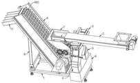
Fig. 1 is a schematic view of the overall structure of the present invention.
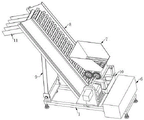
FIG. 2 is a schematic view of the present invention with a section of the conveyor assembly removed.
FIG. 3 is a schematic view of a segment of the conveyor assembly of the present invention.
Fig. 4 is a schematic structural diagram of the blanking control assembly of the present invention.
Fig. 5 is a schematic view of an assembly structure of a third motor and a filtrate impeller according to the present invention.
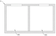
FIG. 6 is a sectional view of the collection chamber of the present invention.
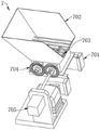
Figure 7 is a schematic view of the shredder assembly of the present invention.
FIG. 8 is a schematic view of a two-stage conveyor assembly according to the present invention.
FIG. 9 is a schematic view of a support assembly according to the present invention.
Fig. 10 is a cross-sectional view of a drain and debris removal channel in accordance with the present invention.
FIG. 11 is a schematic view of the position relationship between the two-stage conveyor assembly and the feed slide of the present invention.
In the figure: 1. a chassis; 2. a length of conveying assembly; 201. a delivery cartridge; 202. a chip inlet pipe orifice; 203. a chip outlet pipe orifice; 204. a packing auger; 205. a first motor; 206. a blanking pipe orifice; 3. a blanking control component; 301. a fixing frame; 302. a pulley; 303. a baffle plate; 304. a toothed plate; 305. a second motor; 306. a first gear; 4. a liquid discharge conduit; 401. a third motor; 402. a filtrate impeller; 5. a chip removal pipe; 6. a collection box; 601. a liquid chamber; 602. a solid chamber; 7. a size reduction assembly; 701. a supporting seat; 702. a crushing hopper; 703. a crushing hammer; 704. a second gear; 705. a fourth motor; 8. a second stage transport assembly; 801. a support plate; 802. a conveyor chain; 803. a collection box; 804. a fifth motor; 805. a base plate; 806. a slide bar; 807. a screw rod; 808. a sixth motor; 9. a support assembly; 901. a fixed base; 902. a bearing plate; 903. a turnover plate; 904. a slip ring; 905. a nut; 10. a feeding sliding plate; 11. and a discharging sliding plate.
Detailed Description
In order to make the technical means, the creation characteristics, the achievement purposes and the effects of the invention easy to understand, the invention is further described with the specific embodiments.
As shown in fig. 1-11, the energy-saving chip removal system for the numerical control machine tool comprises an underframe 1, a first section conveying assembly 2, a crushing assembly 7, a second section conveying assembly 8 and a supporting assembly 9, wherein the first section conveying assembly 2 is horizontally installed at one end of the top of the underframe 1, one end of the second section conveying assembly 8 is hinged and matched in the middle of the top of the underframe 1, the crushing assembly 7 is installed in the center of the top of the underframe 1, a feeding sliding plate 10 is obliquely fixed at a discharge port at the bottom of the crushing assembly 7, the feeding sliding plate 10 is located above the bottom end of the second section conveying assembly 8, the supporting assembly 9 is fixed at one end of the top of the underframe 1, which is far away from the first section conveying assembly 2, the top of the supporting assembly 9 is connected with the bottom of the second section conveying assembly 8, a discharging sliding plate 11 is obliquely installed at one end of the second section conveying assembly 8, the chip removal system is provided with the first section conveying assembly 2 and the second section conveying assembly 8, a complete chip removal function is realized, in the first section conveying assembly 2, a packing auger 204 is driven by a first motor 205 to rotate, and chips generated by the packing auger are discharged out. Carry out the chip removal through the mode of rotating auger 204, on the one hand, one section conveying assembly 2 simple structure, the volume is less, be connected one section conveying assembly 2 with digit control machine tool processing department, it is littleer to the regional space of digit control machine tool processing, thereby reduce the interference when this chip removal system uses digit control machine tool, on the other hand, auger 204 is at a transport section of thick bamboo 201 internal rotation, can produce powerful thrust, can will hang and link the piece of being difficult to the clearance of digit control machine tool or gathering integrated heap and take away, thereby make this chip removal system's chip removal ability stronger. In the second-stage conveying assembly 8, the fifth motor 804 drives the conveying plate chain 802 to convey, the chips conveyed by the first-stage conveying assembly 2 are received and conveyed continuously, meanwhile, the sixth motor 808 drives the screw rod 807 to rotate, the screw rod 807 is rotated, the nut 905 is moved, the nut 905 drives the turnover plate 903 to move, the support point of the bearing plate 902 on the second-stage conveying assembly 8 is changed by moving the turnover plate 903, the inclination angle of the second-stage conveying assembly 8 is further adjusted, the chip removal of the chip removal system is inclined and the chip removal function is improved by adjusting the inclination angle of the second-stage conveying assembly 8, and the chip removal system is more flexible to use on the basis of keeping the use points of the existing chip removal system by matching the first-stage conveying assembly 2 and the second-stage conveying assembly 8 and can solve the problems that the existing spiral chip removal device is only suitable for a chip removal rocker arm drilling machine along the horizontal or small-angle inclined linear direction and cannot be used for large-angle inclination and lifting or steering chip removal;
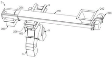
the first-stage conveying assembly 2 comprises a conveying cylinder 201 and an auger 204, a chip inlet pipe orifice 202 is arranged at the top of one end of the conveying cylinder 201, a chip outlet pipe orifice 203 is arranged at the bottom of one end, far away from the chip inlet pipe orifice 202, of the conveying cylinder 201, the chip outlet pipe orifice 203 is located right above a feed inlet of the crushing assembly 7, the auger 204 is in running fit in the conveying cylinder 201, and a first motor 205 for driving the auger 204 to rotate is arranged at one end, close to the chip inlet pipe orifice 202, of the conveying cylinder 201.
Two-stage conveying assembly 8 includes backup pad 801, conveyer plate chain 802 and collection box 803, two backup pad 801 bottoms articulate in chassis 1 top center, two backup pad 801 are the slope setting, conveyer plate chain 802 transmission cooperation is between two backup pad 801, a fifth motor 804 of drive conveyer plate chain 802 transmission is installed to one of them backup pad 801 one side, a plurality of collection box 803 align to grid is fixed on conveyer plate chain 802, through set up collection box 803 on conveyer plate chain 802, collection box 803 can keep in the piece, make two-stage conveying assembly 8 can bear more pieces, and then make two-stage conveying assembly 8's transport capacity stronger, and simultaneously, keep in the piece through collection box 803, make conveyer plate chain 802 also can accomplish the transport to the piece with slower speed, and then the electric quantity that consumes when making conveyer plate chain 802 conveying operation lower, thereby make this chip removal system more energy-conserving, simultaneously, keep in the piece through collecting box 803, make the piece slide down on conveyer plate chain 802 of two-stage conveying assembly 8, thereby make the use of this chip removal system more reliable.
In an optional implementation manner of this embodiment, a feeding nozzle 206 is connected to and penetrates through the middle bottom of the conveying cylinder 201, and the feeding control assembly 3 is installed at the bottom of the feeding nozzle 206.
In an optional implementation manner of this embodiment, unloading control assembly 3 includes fixed frame 301, pulley 302 and baffle 303, the mesh has been seted up to baffle 303, fixed frame 301 passes through the bolt fastening in the bottom of conveying cylinder 201, and the through-hole of fixed frame 301 aligns with the through-hole of unloading mouth of pipe 206, two rows of pulleys 302 are all installed to fixed frame 301 both sides inner wall, baffle 303 passes through pulley 302 pull cooperation in fixed frame 301, filter out cutting fluid in the piece through baffle 303, separate cutting fluid and tiny piece through filtrating impeller 402, avoid cutting fluid to get into among the crushing unit 7, and then avoid cutting fluid to influence the crushing effect of crushing unit 7, and simultaneously, avoid cutting fluid trickling everywhere, cause the pollution to the surrounding environment, thereby further improve the feature of environmental protection that this chip removal system used, carry out the chip removal through this chip removal system, and in the chip removal in-process with the cutting fluid separation, and then make the follow-up piece processing more convenient, thereby improve the convenience of this chip removal component use.
In an optional implementation manner of this embodiment, the bottom of the baffle 303 is fixed with the toothed plate 304 through a bolt, a second motor 305 is horizontally installed on one side of the fixing frame 301, the second motor 305 is connected with a first gear 306 through a rotating shaft, the first gear 306 is engaged with the toothed plate 304, the first gear 306 drives the first gear 306 to rotate through the second motor 305, the first gear 306 is engaged with the toothed plate 304 to drive the baffle 303 to move, by moving the baffle 303, the baffle 303 can be moved away from the blanking pipe orifice 206, so that the chips in the conveying cylinder 201 can directly enter the collecting box 6, under the condition that the workload of a numerical control machine tool for installing the chip removal system is small, the chip removal system can only open one section of the conveying assembly 2 to remove chips, and the chips are discharged into the collecting box 6, thus, under the condition that the workload of the numerical control machine tool is small, the electric quantity can be saved more, and the chip removal system is more energy-saving.
In an optional embodiment of this embodiment, a collection box 6 is fixed at a top of the chassis 1 near one end of a section of the conveying assembly 2, a liquid cavity 601 and a solid cavity 602 are arranged inside the collection box 6, a liquid discharge pipe 4 is connected to a top of the collection box 6, the liquid discharge pipe 4 is communicated with the liquid cavity 601, a top of the liquid discharge pipe 4 is connected to the fixing frame 301, a chip discharge pipe 5 is connected to one side of the liquid discharge pipe 4, a bottom of the chip discharge pipe 5 is connected to the collection box 6, the chip discharge pipe 5 is communicated with the solid cavity 602, the section of the conveying assembly 2 is fixed to the collection box 6 through the liquid discharge pipe 4 and the chip discharge pipe 5, by providing a discharge pipe opening 206 on the conveying cylinder 201, and installing the discharge control assembly 3 at the discharge pipe opening 206, a baffle 303 in the discharge control assembly 3 can filter chips in the conveying cylinder 201, so that fine chips and cutting liquid enter the liquid discharge pipe 4 through the baffle 303 and fall on the filtrate impeller 402, the cutting liquid passes through a mesh on a blade of the filtrate impeller 402, the filtrate enters the liquid cavity 601 of the collecting box 6 through the liquid discharge pipe 4, thereby preventing the fine debris from entering a subsequent environment where the chip discharge pipe 5 and preventing the debris from entering into the environment where the environment pollution caused by the debris discharge system, and preventing the debris from entering the environment pollution caused by the environment, the debris from entering into the environment where the debris discharge pipe 5, the debris discharge system, thereby preventing the debris from entering into the environment, when guaranteeing like this that the liquid that gets into in drain 4 when liquid drain 4 and chip removal pipeline 5 intercommunication department, liquid sees through the vertical downwards of filtrating impeller 402, continue to get into liquid chamber 601 along drain 4, can not flow into in the chip removal pipeline 5, and simultaneously, drain 4 and chip removal pipeline 5 intercommunication department keep away from chip removal pipeline 5 one side inner wall and be equipped with the arc wall with filtrating impeller 402 adaptation, filtrating impeller 402 rotates in the arc wall, and the arc wall inner wall is hugged closely to filtrating impeller 402's blade, filtrating impeller 402 is when rotating, the edge that has a blade at least laminates with drain 4 arc wall inner walls, guaranteed like this that the piece can not get into liquid chamber 601 from filtrating impeller 402's edge.
In an optional implementation manner of this embodiment, a filtrate impeller 402 is rotatably fitted at a communication position between the drainage pipeline 4 and the debris discharge pipeline 5 in the drainage pipeline 4, fine meshes are formed on blades of the filtrate impeller 402, the aperture of the meshes on the blades is smaller than that of the meshes on the baffle 303, and a third motor 401 for driving the filtrate impeller 402 to rotate is installed on the outer side wall of the drainage pipeline 4.
In an optional implementation manner of this embodiment, the crushing assembly 7 includes a support seat 701, a crushing hopper 702 and a crushing hammer 703, the support seat 701 is fixed on the feeding sliding plate 10, the support seat 701 is fixed on the top of the chassis 1 through the feeding sliding plate 10, the crushing hopper 702 is installed on the support seat 701, two crushing hammers 703 are both in running fit in the crushing hopper 702, two second gears 704 connected with the two crushing hammers 703 are in running fit on the outer side wall of the crushing hopper 702, the two second gears 704 are meshed with each other, a fourth motor 705 for driving one of the second gears 704 to rotate is installed on one side of the support seat 701, by setting the crushing assembly 7, under the driving of the fourth motor 705, the crushing hammer 703 is rotated to crush the chips, on one hand, the chips are crushed by the crushing assembly 7, so that the chips discharged by the chip discharge system are smaller, and further, when the chips discharged by the chip discharge system are stored, the occupation of space is smaller, and further, the following chips discharged by transferring the chip discharge system are more convenient, and at the same time, the following chips discharged by recycling the system is more convenient to use.
In an optional implementation manner of this embodiment, bottom plates 805 are fixed to bottoms of two supporting plates 801, two sliding rods 806 are fixed to bottoms of the bottom plates 805, the supporting assembly 9 includes a fixed base 901, a bearing plate 902, and a flipping plate 903, the fixed base 901 is fixed to the top of the base frame 1, the bearing plate 902 is in hinged fit with the fixed base 901, the flipping plate 903 is in rotational fit with the top of the bearing plate 902, two sliding rings 904 are welded to the top of the flipping plate 903, and the two sliding rings 904 are respectively sleeved on the two sliding rods 806.
In an optional implementation manner of this embodiment, a screw rod 807 is rotatably fitted between the two sliding bars 806 at the bottom of the bottom plate 805, a sixth motor 808 for driving the screw rod 807 to rotate is mounted at one end of the bottom plate 805, a nut 905 is fixed at the top of the turning plate 903 between the two sliding rings 904, and the nut 905 is in threaded fit with the screw rod 807.
When the chip discharging system is used, firstly, the chip discharging system is installed on a numerical control machine tool, a chip inlet pipe orifice 202 of the chip discharging system is positioned under a numerical control machine tool machining area, waste chips generated in the numerical control machine tool machining process can fall down into the chip inlet pipe orifice 202, chips generated in the numerical control machine tool machining production process enter a conveying cylinder 201 from the chip inlet pipe orifice 202, the auger 204 is driven by a first motor 205 to rotate in the conveying cylinder 201, the chips in the conveying cylinder 201 are conveyed to a chip outlet pipe orifice 203 by rotating the auger 204, when the chips pass through a discharging pipe orifice 206 in the conveying cylinder 201, cutting fluid and fine chips doped in the chips enter a liquid discharging pipeline 4 through meshes on a baffle 303 and fall onto a filtrate impeller 402, the cutting fluid penetrates through meshes on blades of the filtrate impeller 402 and enters a liquid cavity 601 for storing liquid in a collecting box 6 through the liquid discharging pipeline 4, fine chips are filtered on the blades of the filtrate impeller 402 and are driven by a third motor 401 to rotate the filtrate impeller 402, the fine chips on the blades of the filtrate impeller 402 are brought into the solid chips in the collecting box 5 through the chip discharging pipeline 5 and are used for storing solid chips in the collecting box 602 through the solid chip discharging box 6; through setting up unloading mouth of pipe 206 on transport cylinder 201, and install unloading control assembly 3 in unloading mouth of pipe 206 department, baffle 303 in the unloading control assembly 3, can filter the piece in transport cylinder 201, make tiny piece and cutting fluid permeate baffle 303 and get into in the drain pipe 4, and fall on filtrating impeller 402, the cutting fluid permeates the mesh on filtrating impeller 402 blade, get into the liquid chamber 601 that is used for depositing liquid in the collecting box 6 through the drain pipe 4, tiny piece passes through pivoted filtrating impeller 402, get into in the chip removal pipeline 5, filter tiny piece through baffle 303, tiny piece has been avoided getting into crushing unit 7 from transport cylinder 201, when avoiding tiny piece to float everywhere from a bits mouth of pipe 203 discharges, and then avoided causing the pollution to the environment, thereby improve the environmental protection nature of this chip removal system use, simultaneously, the work burden of follow-up tiny piece that floats has also been reduced, bring the facility for the cleaning work behind this chip removal system. Filter out the cutting fluid in with the piece through baffle 303, separate cutting fluid and tiny piece through filtrating impeller 402, avoid cutting fluid to get into crushing unit 7, and then avoid the cutting fluid to influence crushing unit 7's crushing effect, and simultaneously, avoid the cutting fluid trickling everywhere, cause the pollution to the surrounding environment, thereby further improve the feature of environmental protection that this chip removal system used, carry out the chip removal through this chip removal system, and in the chip removal in-process with the cutting fluid separation, and then make the follow-up processing piece more convenient, thereby improve the convenience that this chip removal component used.
The first gear 306 is driven by the second motor 305 to rotate, the first gear 306 is meshed with the toothed plate 304 to drive the baffle 303 to move, the baffle 303 can be moved away from the blanking pipe orifice 206 by moving the baffle 303, so that the chips in the conveying cylinder 201 can directly enter the collecting box 6, and under the condition that the workload of a numerical control machine for installing the chip removal system is small, the chip removal system can only open one section of conveying assembly 2 to remove chips and discharge the chips into the collecting box 6.
Then, the chips filtered by the baffle 303 are left in the conveying cylinder 201, the chips are pushed to the chip outlet pipe opening 203 through the auger 204, the chips fall into the crushing hopper 702 of the crushing assembly 7, the chips are driven by the fourth motor 705, the second gear 704 is driven to rotate, the two second gears 704 are simultaneously rotated due to meshing, the two rotating second gears 704 respectively drive the two crushing hammers 703 to rotate, the chips in the crushing hopper 702 are crushed by rotating the crushing hammers 703, the chips can be temporarily stored by the collecting box 803 arranged on the conveying plate chain 802, the two-section conveying assembly 8 can bear more chips, further the conveying capacity of the two-section conveying assembly 8 is stronger, meanwhile, the chips are temporarily stored by the collecting box 803, the conveying plate chain 802 can also complete conveying of the chips at a slower speed, further, the consumed electric quantity during the conveying operation of the conveying plate chain 802 is lower, further, the chip removal system is more energy-saving, meanwhile, the chips are temporarily stored by the collecting box 803, the chips are made to not easily slide down on the conveying plate chain 802 of the two-section conveying assembly 8, and further the chip removal system is more reliable in use. Through setting up crushing unit 7, under the drive of fourth motor 705, rotate crushing hammer 703 and smash the piece, on the one hand, smash the piece through crushing unit 7, make this chip removal system exhaust piece granule littleer, and then when making deposit this chip removal system exhaust piece, occupy littleer to the space, and then make the follow-up piece of transporting this chip removal system exhaust of transporting more convenient, and simultaneously, also make follow-up piece recycle to this system exhaust more convenient, thereby improve the convenience that this chip removal system used, finally, the piece through crushing unit 7 kibbling falls into collection box 803 on two-stage conveyor assembly 8 through feeding slide 10, drive conveyer plate chain 802 transmission through fifth motor 804, conveyer plate chain 802 drives collection box 803 and removes, convey the piece through removing collection box 803, when collection box 803 conveys to ejection of compact slide 11 department, place the collection frame in ejection of compact slide 11 bottom, the piece in the ejection of compact slide 11 pours into the collection frame that prepares in advance through ejection of compact slide 11. The chip removal system is provided with a first-section conveying assembly 2 and a second-section conveying assembly 8, the first-section conveying assembly 2 is matched with the second-section conveying assembly 8, a complete chip removal function is achieved, in the first-section conveying assembly 2, an auger 204 is driven to rotate through a first motor 205, chips generated by a numerical control machine tool are discharged, and chips are removed in a mode of rotating the auger 204; in two-stage segment conveying assembly 8, drive conveying plate chain 802 conveying through fifth motor 804, the piece that conveys one section conveying assembly 2 receives and continues to carry, and simultaneously, drive lead screw 807 through sixth motor 808 and rotate, make nut 905 remove through rotating lead screw 807, nut 905 drives returning face plate 903 and removes, through removing returning face plate 903, change the strong point of bearing plate 902 to two-stage segment conveying assembly 8, and then adjust two-stage segment conveying assembly 8's inclination, through adjusting two-stage segment conveying assembly 8's inclination, make this chip removal system's chip removal realize the slope, promote the chip removal function, through one section conveying assembly 2 and two-stage segment conveying assembly 8 cooperation, only be fit for along level or small-angle slope straight line direction chip removal rocker arm drilling machine that current spiral chip removal device exists, can not be used for the large angle slope, promote or turn to the problem of chip removal, thereby make this chip removal system use on the basis that current spiral chip removal device has some, it is more nimble to use.
The foregoing shows and describes the general principles, principal features and advantages of the invention. It will be understood by those skilled in the art that the present invention is not limited to the embodiments described above, and the embodiments and descriptions given above are only illustrative of the principles of the present invention, and various changes and modifications may be made without departing from the spirit and scope of the invention, which fall within the scope of the claims. The scope of the invention is defined by the appended claims and equivalents thereof.
Claims (10)
1. The utility model provides an energy-conserving chip removal system for digit control machine tool, includes chassis (1), one section conveyor components (2), crushing unit (7), two-stage segment conveyor components (8) and supporting component (9), its characterized in that: the device comprises a base frame (1), a first section conveying assembly (2), a second section conveying assembly (8), a crushing assembly (7), a support assembly (9), a feeding sliding plate (10), a discharging sliding plate (11) and a discharging sliding plate (2), wherein the first section conveying assembly (2) is horizontally arranged at one end of the top of the base frame (1), one end of the second section conveying assembly (8) is hinged and matched in the middle of the top of the base frame (1), the crushing assembly (7) is arranged at the center of the top of the base frame (1), the discharging opening at the bottom of the crushing assembly (7) is obliquely fixed with the feeding sliding plate (10), the feeding sliding plate (10) is positioned above the bottom end of the second section conveying assembly (8), the support assembly (9) is fixed at one end, far away from the first section conveying assembly (2), of the top of the support assembly (9) is connected with the bottom of the second section conveying assembly (8), and the discharging sliding plate (11) is obliquely arranged at one end, far away from the first section conveying assembly (2), of the second section conveying assembly (8);
wherein, one section of conveyor components (2) are including carrying a section of thick bamboo (201) and auger (204), carry a section of thick bamboo (201) one end top to be provided with into bits mouth of pipe (202), the bottom of keeping away from into bits mouth of pipe (202) one end of carrying a section of thick bamboo (201) is provided with out bits mouth of pipe (203), it is located directly over crushing unit (7) feed inlet to go out bits mouth of pipe (203), auger (204) normal running fit is in carrying a section of thick bamboo (201), the one end that carries a section of thick bamboo (201) to be close to into bits mouth of pipe (202) is installed and is driven auger (204) pivoted first motor (205).
2. An energy-saving chip removal system for numerical control machine tools according to claim 1, characterized in that: two-stage conveying subassembly (8) are including backup pad (801), conveying board chain (802) and collection box (803), two backup pad (801) bottom articulates at chassis (1) top center, and two backup pad (801) are the slope setting, conveying board chain (802) transmission cooperation is between two backup pad (801), and driven conveying board chain (802) driven fifth motor (804), a plurality of are installed to one of them backup pad (801) one side collecting box (803) align to grid fixes on conveying board chain (802), and the bottom is connected and is link up there is unloading mouth of pipe (206) in the middle of conveying cylinder (201), and unloading control assembly (3) are installed to the bottom of unloading mouth of pipe (206).
3. An energy-saving chip removal system for numerical control machine tools according to claim 2, characterized in that: unloading control assembly (3) are including fixed frame (301), pulley (302) and baffle (303), the mesh has been seted up in baffle (303), fixed frame (301) are passed through the bolt fastening in a transport section of thick bamboo (201) bottom, and the through-hole of fixed frame (301) aligns with the through-hole of unloading mouth of pipe (206), two rows of pulleys (302) are all installed to fixed frame (301) both sides inner wall, baffle (303) pass through pulley (302) pull cooperation in fixed frame (301).
4. An energy-saving chip removal system for numerical control machine tools according to claim 3, characterized in that: the bottom of the baffle plate (303) is fixed with a toothed plate (304) through a bolt, one side of the fixed frame (301) is horizontally provided with a second motor (305), the second motor (305) is connected with a first gear (306) through a rotating shaft, and the first gear (306) is meshed with the toothed plate (304).
5. An energy-saving chip removal system for numerical control machine tools according to claim 3, characterized in that: chassis (1) top is close to the one end of one section conveying component (2) and is fixed with collecting box (6), collecting box (6) inside is provided with liquid chamber (601) and solid chamber (602), the top of collecting box (6) is connected with drain pipe (4), drain pipe (4) and liquid chamber (601) intercommunication, drain pipe (4) top is connected with fixed frame (301), drain pipe (4) one side is connected and is link up chip removal pipeline (5), the bottom and the collecting box (6) of chip removal pipeline (5) are connected, and chip removal pipeline (5) and solid chamber (602) intercommunication, one section conveying component (2) are fixed on collecting box (6) through drain pipe (4) and chip removal pipeline (5).
6. An energy-saving chip removal system for numerical control machine tools according to claim 5, characterized in that: be located drain pipe (4) and chip removal pipeline (5) intercommunication department normal running fit in drain pipe (4) and have filtrating impeller (402), seted up tiny mesh on the blade of filtrating impeller (402), the mesh aperture on the blade is less than the aperture of mesh on baffle (303), and drive filtrating impeller (402) pivoted third motor (401) are installed to drain pipe (4) lateral wall.
7. An energy-saving chip removal system for numerical control machine tools according to claim 2, characterized in that: crushing unit (7) are including supporting seat (701), smash fill (702) and crushing hammer (703), supporting seat (701) are fixed on feed slide (10), supporting seat (701) are fixed at chassis (1) top through feed slide (10), smash fill (702) and install on supporting seat (701), two equal normal running fit of crushing hammer (703) are in smashing fill (702), smash fill (702) lateral wall normal running fit have two second gear (704) of being connected with two crushing hammers (703) respectively, two second gear (704) intermeshing, supporting seat (701) one side is installed and is driven one of them second gear (704) pivoted fourth motor (705).
8. An energy-saving chip removal system for numerical control machine tools according to claim 2, characterized in that: the bottom of the two supporting plates (801) is fixed with a bottom plate (805), the bottom of the bottom plate (805) is fixed with two sliding rods (806), the supporting component (9) comprises a fixed base (901), a bearing plate (902) and a turnover plate (903), the fixed base (901) is fixed at the top of the base frame (1), the bearing plate (902) is hinged and matched on the fixed base (901), the turnover plate (903) is rotatably matched at the top of the bearing plate (902), the top of the turnover plate (903) is welded with two sliding rings (904), and the two sliding rings (904) are respectively sleeved on the two sliding rods (806).
9. An energy-saving chip removal system for numerical control machine tools according to claim 8, characterized in that: the screw rod (807) is arranged between the two sliding rods (806) at the bottom of the bottom plate (805) in a rotating fit mode, a sixth motor (808) for driving the screw rod (807) to rotate is installed at one end of the bottom plate (805), a nut (905) is fixed between the two sliding rings (904) at the top of the turning plate (903), and the nut (905) is in threaded fit with the screw rod (807).
10. Use of an energy-saving chip removal system for numerical control machine tools according to any one of claims 1 to 9, characterized in that: the using method of the chip removal system specifically comprises the following steps:
the method comprises the following steps: the chip removal system is installed on a numerical control machine tool, chips generated in the machining and production process of the numerical control machine tool enter a conveying cylinder (201) from a chip inlet pipe orifice (202), an auger (204) rotates in the conveying cylinder (201) through rotation of a first motor (205), the chips in the conveying cylinder (201) are conveyed to a chip outlet pipe orifice (203) through rotation of the auger (204), when the chips pass through a blanking pipe orifice (206) in the conveying cylinder (201), cutting fluid and fine chips doped in the chips enter a liquid discharge pipeline (4) through meshes in a baffle plate (303) and fall on a filtrate impeller (402), the cutting fluid penetrates through meshes in blades of the filtrate impeller (402) and enters a liquid cavity (601) for storing liquid in a collecting box (6) through the liquid discharge pipeline (4), the fine chips are filtered on the blades of the filtrate impeller (402), the filtrate impeller (402) is driven by a third motor (401) to rotate the filtrate impeller (402), and the fine chips on the blades of the filtrate impeller (402) are brought into a solid chip discharge pipeline (5) for storing the solid chips in the collecting box (602) through rotation of the filtrate impeller (402);
step two: the scraps filtered by the baffle (303) are left in the conveying cylinder (201), the scraps are pushed to the scrap outlet pipe opening (203) through the packing auger (204), the scraps fall into the crushing hopper (702) of the crushing assembly (7), the second gear (704) is driven to rotate through the fourth motor (705), the two second gears (704) rotate simultaneously due to meshing, the two rotating second gears (704) respectively drive the two crushing hammers (703) to rotate, and the scraps in the crushing hopper (702) are crushed through rotating the crushing hammers (703);
step three: the smashed piece of process crushing unit (7) falls into collection box (803) on two-stage conveying assembly (8) through feeding slide (10), drive conveying plate chain (802) transmission through fifth motor (804), conveying plate chain (802) drive collection box (803) removal, collect box (803) through removing, convey the piece, when collecting box (803) conveying ejection of compact slide (11) department, place the collection frame in ejection of compact slide (11) bottom, the piece in ejection of compact slide (11) pours into the collection frame of preparing in advance through ejection of compact slide (11).
Priority Applications (1)
| Application Number | Priority Date | Filing Date | Title |
|---|---|---|---|
| CN202211269593.2A CN115337996B (en) | 2022-10-18 | 2022-10-18 | Energy-saving chip removal system for numerical control machine tool and using method |
Applications Claiming Priority (1)
| Application Number | Priority Date | Filing Date | Title |
|---|---|---|---|
| CN202211269593.2A CN115337996B (en) | 2022-10-18 | 2022-10-18 | Energy-saving chip removal system for numerical control machine tool and using method |
Publications (2)
| Publication Number | Publication Date |
|---|---|
| CN115337996A true CN115337996A (en) | 2022-11-15 |
| CN115337996B CN115337996B (en) | 2022-12-27 |
Family
ID=83957526
Family Applications (1)
| Application Number | Title | Priority Date | Filing Date |
|---|---|---|---|
| CN202211269593.2A Active CN115337996B (en) | 2022-10-18 | 2022-10-18 | Energy-saving chip removal system for numerical control machine tool and using method |
Country Status (1)
| Country | Link |
|---|---|
| CN (1) | CN115337996B (en) |
Citations (12)
| Publication number | Priority date | Publication date | Assignee | Title |
|---|---|---|---|---|
| JPH06238545A (en) * | 1993-02-15 | 1994-08-30 | San Techno:Kk | Coolant separating device |
| JP2000229208A (en) * | 1999-02-08 | 2000-08-22 | Noritake Co Ltd | Chip separation device |
| CN207289603U (en) * | 2017-09-14 | 2018-05-01 | 诸城市卓益数控设备有限公司 | Machining center chip cleaner |
| CN210875511U (en) * | 2019-06-24 | 2020-06-30 | 青岛松瑞和机械制造有限公司 | Discharge device of numerical control machine tool |
| CN213469734U (en) * | 2020-10-29 | 2021-06-18 | 重庆龙煜精密铜管有限公司 | Chip removal device for face milling machine |
| CN213889239U (en) * | 2020-12-15 | 2021-08-06 | 广州市品佳机床配件有限公司 | Small chip removal device |
| CN113231138A (en) * | 2021-06-07 | 2021-08-10 | 青岛黄海学院 | Waste material separation device of numerical control machine tool and working method thereof |
| CN214722728U (en) * | 2021-06-02 | 2021-11-16 | 厦门华和霖精密工业有限公司 | Scrap collecting device is used in production of metal radiator shunt tubes |
| CN214877989U (en) * | 2021-05-12 | 2021-11-26 | 江苏锐特自控科技有限公司 | Oblique belt feeder |
| CN215281082U (en) * | 2021-02-06 | 2021-12-24 | 茂名挚诚石化机械科技有限公司 | Automatic chip removal machine for drilling machine |
| CN216986518U (en) * | 2022-04-08 | 2022-07-19 | 贺忠媛 | Municipal administration plumbing is with having sewage solid-liquid separation equipment who prevents stifled function |
| CN217453168U (en) * | 2022-04-21 | 2022-09-20 | 马鞍山昇工智能科技有限公司 | Spiral chip removal device for machine tool |
-
2022
- 2022-10-18 CN CN202211269593.2A patent/CN115337996B/en active Active
Patent Citations (12)
| Publication number | Priority date | Publication date | Assignee | Title |
|---|---|---|---|---|
| JPH06238545A (en) * | 1993-02-15 | 1994-08-30 | San Techno:Kk | Coolant separating device |
| JP2000229208A (en) * | 1999-02-08 | 2000-08-22 | Noritake Co Ltd | Chip separation device |
| CN207289603U (en) * | 2017-09-14 | 2018-05-01 | 诸城市卓益数控设备有限公司 | Machining center chip cleaner |
| CN210875511U (en) * | 2019-06-24 | 2020-06-30 | 青岛松瑞和机械制造有限公司 | Discharge device of numerical control machine tool |
| CN213469734U (en) * | 2020-10-29 | 2021-06-18 | 重庆龙煜精密铜管有限公司 | Chip removal device for face milling machine |
| CN213889239U (en) * | 2020-12-15 | 2021-08-06 | 广州市品佳机床配件有限公司 | Small chip removal device |
| CN215281082U (en) * | 2021-02-06 | 2021-12-24 | 茂名挚诚石化机械科技有限公司 | Automatic chip removal machine for drilling machine |
| CN214877989U (en) * | 2021-05-12 | 2021-11-26 | 江苏锐特自控科技有限公司 | Oblique belt feeder |
| CN214722728U (en) * | 2021-06-02 | 2021-11-16 | 厦门华和霖精密工业有限公司 | Scrap collecting device is used in production of metal radiator shunt tubes |
| CN113231138A (en) * | 2021-06-07 | 2021-08-10 | 青岛黄海学院 | Waste material separation device of numerical control machine tool and working method thereof |
| CN216986518U (en) * | 2022-04-08 | 2022-07-19 | 贺忠媛 | Municipal administration plumbing is with having sewage solid-liquid separation equipment who prevents stifled function |
| CN217453168U (en) * | 2022-04-21 | 2022-09-20 | 马鞍山昇工智能科技有限公司 | Spiral chip removal device for machine tool |
Also Published As
| Publication number | Publication date |
|---|---|
| CN115337996B (en) | 2022-12-27 |
Similar Documents
| Publication | Publication Date | Title |
|---|---|---|
| CN108580516B (en) | Mechanical pretreatment system and pretreatment process for kitchen waste | |
| CN215162016U (en) | Sludge solid waste impurity separating device | |
| CN112827641B (en) | Mineral separation and gravity separation process and equipment for extremely fine fluorite | |
| CN115337996B (en) | Energy-saving chip removal system for numerical control machine tool and using method | |
| CN110963628B (en) | Machining center cutting fluid purifier | |
| CN112473898A (en) | Construction waste treatment device | |
| CN117047537A (en) | Centralized processing equipment and filtering method for cutting fluid of high-end machine tool | |
| CN220740337U (en) | Double-layer roller chip removing machine | |
| CN217831203U (en) | Kitchen waste pretreatment system | |
| CN214054553U (en) | Chip removal device of vertical machining center machine | |
| CN216228233U (en) | Chip and pill separating device of milling and shot blasting combined machining all-in-one machine | |
| CN113953881A (en) | Large-traffic cyclic utilization system of cutting fluid for machining center | |
| CN209772764U (en) | Screw rod separator | |
| CN110201973B (en) | Waste liquid collecting and conveying device suitable for landfill leachate coupling purification | |
| CN211914940U (en) | Kitchen waste rapid treatment vehicle | |
| CN210586149U (en) | Multistage grit washing machine | |
| CN113210111A (en) | Food waste treatment all-in-one | |
| CN112774810A (en) | Metal garbage screening device for garbage disposal | |
| CN112896877A (en) | Complete self-unloading system for kitchen vehicle | |
| CN220839228U (en) | Chip removal mechanism for numerical control machine tool | |
| CN218502935U (en) | Modularized integrated box for kitchen pretreatment | |
| CN216228251U (en) | Machining center waste recovery device | |
| CN219731456U (en) | Inclined conveyor for pulping and shredding waste paper board by dry method | |
| CN220590321U (en) | Building rubbish recovery unit with drainage function | |
| CN220217467U (en) | Lathe bed structure of inclined lathe bed lathe |
Legal Events
| Date | Code | Title | Description |
|---|---|---|---|
| PB01 | Publication | ||
| PB01 | Publication | ||
| SE01 | Entry into force of request for substantive examination | ||
| SE01 | Entry into force of request for substantive examination | ||
| GR01 | Patent grant | ||
| GR01 | Patent grant |