CN115327552B - A scanning optical machine and scanning trajectory control method of a double optical wedge lidar - Google Patents
A scanning optical machine and scanning trajectory control method of a double optical wedge lidar Download PDFInfo
- Publication number
- CN115327552B CN115327552B CN202211243627.0A CN202211243627A CN115327552B CN 115327552 B CN115327552 B CN 115327552B CN 202211243627 A CN202211243627 A CN 202211243627A CN 115327552 B CN115327552 B CN 115327552B
- Authority
- CN
- China
- Prior art keywords
- wedge
- scanning
- optical
- laser
- incident
- Prior art date
- Legal status (The legal status is an assumption and is not a legal conclusion. Google has not performed a legal analysis and makes no representation as to the accuracy of the status listed.)
- Active
Links
- 230000003287 optical effect Effects 0.000 title claims abstract description 107
- 238000000034 method Methods 0.000 title claims abstract description 26
- 230000007246 mechanism Effects 0.000 claims abstract description 11
- 239000013598 vector Substances 0.000 claims description 22
- 238000005259 measurement Methods 0.000 claims description 10
- 238000006243 chemical reaction Methods 0.000 claims description 9
- 239000000835 fiber Substances 0.000 claims description 9
- 238000009434 installation Methods 0.000 claims description 5
- 230000000694 effects Effects 0.000 claims description 3
- 235000012149 noodles Nutrition 0.000 claims description 3
- 230000005540 biological transmission Effects 0.000 claims description 2
- 239000013307 optical fiber Substances 0.000 claims 1
- 238000010586 diagram Methods 0.000 description 7
- 238000007689 inspection Methods 0.000 description 4
- 238000013507 mapping Methods 0.000 description 4
- 230000009977 dual effect Effects 0.000 description 3
- 230000009286 beneficial effect Effects 0.000 description 2
- 238000001514 detection method Methods 0.000 description 1
- 238000005516 engineering process Methods 0.000 description 1
- 238000001914 filtration Methods 0.000 description 1
- 239000012535 impurity Substances 0.000 description 1
- 230000001902 propagating effect Effects 0.000 description 1
- 230000035939 shock Effects 0.000 description 1
Images


Classifications
-
- G—PHYSICS
- G01—MEASURING; TESTING
- G01S—RADIO DIRECTION-FINDING; RADIO NAVIGATION; DETERMINING DISTANCE OR VELOCITY BY USE OF RADIO WAVES; LOCATING OR PRESENCE-DETECTING BY USE OF THE REFLECTION OR RERADIATION OF RADIO WAVES; ANALOGOUS ARRANGEMENTS USING OTHER WAVES
- G01S17/00—Systems using the reflection or reradiation of electromagnetic waves other than radio waves, e.g. lidar systems
- G01S17/02—Systems using the reflection of electromagnetic waves other than radio waves
-
- G—PHYSICS
- G01—MEASURING; TESTING
- G01S—RADIO DIRECTION-FINDING; RADIO NAVIGATION; DETERMINING DISTANCE OR VELOCITY BY USE OF RADIO WAVES; LOCATING OR PRESENCE-DETECTING BY USE OF THE REFLECTION OR RERADIATION OF RADIO WAVES; ANALOGOUS ARRANGEMENTS USING OTHER WAVES
- G01S7/00—Details of systems according to groups G01S13/00, G01S15/00, G01S17/00
- G01S7/48—Details of systems according to groups G01S13/00, G01S15/00, G01S17/00 of systems according to group G01S17/00
- G01S7/481—Constructional features, e.g. arrangements of optical elements
- G01S7/4817—Constructional features, e.g. arrangements of optical elements relating to scanning
-
- Y—GENERAL TAGGING OF NEW TECHNOLOGICAL DEVELOPMENTS; GENERAL TAGGING OF CROSS-SECTIONAL TECHNOLOGIES SPANNING OVER SEVERAL SECTIONS OF THE IPC; TECHNICAL SUBJECTS COVERED BY FORMER USPC CROSS-REFERENCE ART COLLECTIONS [XRACs] AND DIGESTS
- Y02—TECHNOLOGIES OR APPLICATIONS FOR MITIGATION OR ADAPTATION AGAINST CLIMATE CHANGE
- Y02A—TECHNOLOGIES FOR ADAPTATION TO CLIMATE CHANGE
- Y02A90/00—Technologies having an indirect contribution to adaptation to climate change
- Y02A90/10—Information and communication technologies [ICT] supporting adaptation to climate change, e.g. for weather forecasting or climate simulation
Landscapes
- Engineering & Computer Science (AREA)
- Physics & Mathematics (AREA)
- Computer Networks & Wireless Communication (AREA)
- General Physics & Mathematics (AREA)
- Radar, Positioning & Navigation (AREA)
- Remote Sensing (AREA)
- Electromagnetism (AREA)
- Optical Radar Systems And Details Thereof (AREA)
Abstract
本发明提供了一种双光楔激光雷达扫描光机及扫描轨迹控制方法,涉及激光雷达技术领域。双光楔激光雷达扫描光机包括设于机体内的底座,底座上设有激光入射单元,底座上、下部的机体内分别设有扫描、接收单元,扫描单元包括两组扫描机构,扫描机构包括转动设置于机体内的光楔,激光入射单元包括设于扫描单元底部的反射镜,激光入射单元射出的激光通过反射镜反射面的偏转后依次穿过两光楔。扫描轨迹控制方法包括:光楔初始相位对齐和相位控制,光楔初始相位对齐是通过两个分体式直流电机转角的控制,实现两光楔不同的初始角度控制;光楔相位控制是通过两个分体式直流电机转动速度的控制,实现两光楔在连续旋转过程中不同的相对角度控制。

The invention provides a double optical wedge laser radar scanning optical machine and a scanning trajectory control method, and relates to the technical field of laser radar. The double-wedge laser radar scanning optical machine includes a base set in the body. The base is equipped with a laser incident unit. The upper and lower parts of the base are respectively equipped with scanning and receiving units. The scanning unit includes two sets of scanning mechanisms. The scanning mechanism includes Rotate the optical wedge set in the body, the laser incident unit includes a reflector at the bottom of the scanning unit, and the laser light emitted by the laser incident unit passes through the two optical wedges sequentially after being deflected by the reflective surface of the reflector. The scanning trajectory control method includes: the initial phase alignment of the optical wedge and phase control. The initial phase alignment of the optical wedge is controlled by the rotation angle of two split DC motors to realize the different initial angle control of the two optical wedges; the phase control of the optical wedge is achieved by two The control of the rotation speed of the split DC motor realizes the different relative angle control of the two optical wedges in the continuous rotation process.
Description
技术领域technical field
本发明涉及激光雷达技术领域,具体涉及一种双光楔激光雷达扫描光机及扫描轨迹控制方法。The invention relates to the technical field of laser radar, in particular to a scanning optical machine and a scanning trajectory control method of a double optical wedge laser radar.
背景技术Background technique
激光雷达是以发射激光束探测目标的位置、速度等特征量的雷达系统,其工作原理是向目标发射探测信号(激光束),然后将接收到的从目标反射回来的信号(目标回波)与发射信号进行比较,作适当处理后,就可获得目标的有关信息。Lidar is a radar system that emits a laser beam to detect the position, speed and other characteristics of the target. Its working principle is to transmit a detection signal (laser beam) to the target, and then receive the signal reflected from the target (target echo) Compared with the transmitted signal, after proper processing, the relevant information of the target can be obtained.
现有技术中,由于传统激光雷达扫描方式存在扫描视场角小(如摆镜扫描及光学相控阵扫描)和激光脉冲有效利用率低(如旋转多棱镜扫描)的问题,导致传统激光雷达扫描效率低、点云利用率低。In the existing technology, due to the problems of small scanning field of view (such as pendulum mirror scanning and optical phased array scanning) and low effective utilization of laser pulses (such as rotating polygonal mirror scanning) in traditional laser radar scanning methods, traditional laser radar scanning Low efficiency and low point cloud utilization.
发明内容Contents of the invention
本发明的目的是开发一种扫描效率高、点云利用率高的双光楔激光雷达扫描光机及扫描轨迹控制方法。The purpose of the present invention is to develop a dual-wedge laser radar scanning optical machine and a scanning trajectory control method with high scanning efficiency and high point cloud utilization.
本发明通过如下的技术方案实现:The present invention realizes through following technical scheme:
一种双光楔激光雷达扫描光机,包括:A dual optical wedge lidar scanning optical machine, comprising:
机体;body;
底座,设于机体内;The base is arranged in the body;
激光入射单元,设于底座上;The laser incident unit is set on the base;
扫描单元,设于底座上部的机体内;The scanning unit is arranged in the body on the upper part of the base;
接收单元,设于底座下部的机体内;The receiving unit is arranged in the body at the lower part of the base;
其中,所述激光入射单元包括设于扫描单元与接收单元之间的反射镜,所述扫描单元包括两组扫描机构,所述扫描机构包括转动设置于机体内的光楔,所述机体内设有驱动光楔转动的分体式直流电机,所述激光入射单元射出的光源通过反射镜反射面的偏转后依次穿过两个光楔。Wherein, the laser incident unit includes a reflector arranged between the scanning unit and the receiving unit, the scanning unit includes two sets of scanning mechanisms, the scanning mechanisms include an optical wedge rotatably arranged in the body, and the body is equipped with There is a split DC motor that drives the optical wedge to rotate, and the light source emitted by the laser incident unit passes through the two optical wedges sequentially after being deflected by the reflective surface of the mirror.
可选的,所述反射镜的反射面呈椭圆形,其短轴等于进入反射面上的光源光斑直径。Optionally, the reflective surface of the reflective mirror is elliptical, and its minor axis is equal to the diameter of the light spot of the light source entering the reflective surface.
可选的,所述反射镜外部套设有防旁瓣套筒,所述反射镜反射面侧部的防旁瓣套筒上设有入射口,所述防旁瓣套筒顶部设有出射口,所述入射口及出射口的内径与通过它们的光源光斑直径匹配。Optionally, an anti-sidelobe sleeve is sleeved on the outside of the reflector, an entrance is provided on the anti-sidelobe sleeve on the side of the reflective surface of the reflector, and an exit port is provided on the top of the anti-sidelobe sleeve , the inner diameters of the entrance and exit are matched with the spot diameter of the light source passing through them.
可选的,所述激光入射单元还包括:Optionally, the laser incident unit also includes:
入射激光固定座,设于反射镜侧部的底座上;The incident laser fixing seat is set on the base of the side of the reflector;
激光准直器,设于入射激光固定座上;The laser collimator is set on the incident laser fixing seat;
激光光纤,与激光准直器连接;Laser fiber, connected with laser collimator;
其中,所述反射镜的反射面朝向激光准直器。Wherein, the reflecting surface of the reflecting mirror faces the laser collimator.
可选的,所述激光准直器和激光光纤水平设置,所述反射镜的反射面与水平面呈45°夹角设置,两个所述光楔呈竖直线设于反射镜上部。Optionally, the laser collimator and the laser fiber are arranged horizontally, the reflection surface of the reflector is arranged at an angle of 45° to the horizontal plane, and the two optical wedges are arranged vertically on the upper part of the reflector.
可选的,所述扫描单元还包括设于反射镜上部机体内的壳体,所述扫描机构还包括转动设于壳体上的光楔镜筒,所述光楔固定于所述光楔镜筒内,所述分体式直流电机设于壳体上并与光楔镜筒传动连接。Optionally, the scanning unit also includes a casing arranged in the upper body of the reflector, and the scanning mechanism also includes an optical wedge lens barrel that is rotated on the casing, and the optical wedge is fixed to the optical wedge mirror In the barrel, the split type DC motor is arranged on the casing and is connected with the optical wedge lens barrel through transmission.
可选的,所述机体内设有与分体式直流电机配合的伺服驱动器,所述壳体上对应位置设有与光楔镜筒及伺服驱动器配合的增量式角度测量传感器。Optionally, a servo drive that cooperates with the split DC motor is provided in the body, and an incremental angle measurement sensor that cooperates with the optical wedge barrel and the servo drive is provided at a corresponding position on the housing.
可选的,所述接收单元包括设于反射镜下部机体内的接收安装镜筒,所述接收安装镜筒内上下设置有窄带滤光片和非球面接收透镜,所述接收安装镜筒底部设有光电转换传感器。Optionally, the receiving unit includes a receiving installation lens barrel arranged in the lower body of the reflector, a narrowband filter and an aspheric receiving lens are arranged up and down in the receiving installation lens barrel, and the bottom of the receiving installation lens barrel is arranged There is a photoelectric conversion sensor.
可选的,所述接收安装镜筒内对应设有与非球面接收透镜配合的接收透镜安装支撑体,所述接收透镜安装支撑体上设有接收透镜压环,所述接收透镜压环的环面上设有橡胶垫圈,所述窄带滤光片顶部还设有与其配合的滤光片压环,所述滤光片压环与接收透镜安装支撑体连接。Optionally, a receiving lens mounting support that cooperates with an aspheric receiving lens is correspondingly provided in the receiving mounting lens barrel, a receiving lens pressure ring is provided on the receiving lens mounting support, and the ring of the receiving lens pressure ring A rubber gasket is provided on the surface, and a filter pressure ring matched with the narrow band filter is provided on the top, and the filter pressure ring is connected with the receiving lens mounting support.
一种双光楔激光雷达扫描光机的扫描轨迹控制方法,通过光楔初始相位对齐和相位控制,使不同的初始相位和相位控制实现不同的扫描脚点轨迹控制;A scanning track control method for a double-wedge laser radar scanning optical machine, through the initial phase alignment and phase control of the optical wedge, different initial phases and phase controls can be used to achieve different scanning foot track control;
其中,光楔初始相位对齐是通过两个分体式直流电机转角的控制,实现两个光楔不同的初始角度控制;Among them, the initial phase alignment of the optical wedge is controlled by the rotation angle of the two split DC motors to realize the different initial angle control of the two optical wedges;
光楔相位控制是通过两个分体式直流电机转动速度的控制,实现两个光楔在连续旋转过程中不同的相对角度控制。The optical wedge phase control is through the control of the rotation speed of two split DC motors to realize the different relative angle control of the two optical wedges in the continuous rotation process.
本发明的有益效果是:The beneficial effects of the present invention are:
1.采用双楔形镜折射,单个光楔偏转角达到30°,最大偏转角±30°,扫描视场大,双光楔扫描采用激光折射方式,有效减小系统的体积,可将点云全部分布在±30°的视场角范围内,光学利用率可达到100%;1. Double-wedge mirror refraction is adopted, the deflection angle of a single wedge reaches 30°, the maximum deflection angle is ±30°, and the scanning field of view is large. The double-wedge scanning adopts the laser refraction method, which effectively reduces the volume of the system and can capture all point clouds. Distributed within the field of view range of ±30°, the optical utilization rate can reach 100%;
3.分体式直流电机为内转子电机,转子和光楔镜筒刚性连接,带动光楔镜筒和光楔旋转,可以提高设备稳定度,抗震效果好,分体式直流电机转速快,速度可控,并由伺服驱动器控制,实现转速和转角的精准控制,扫描速度快;3. The split type DC motor is an inner rotor motor. The rotor is rigidly connected with the optical wedge lens barrel, which drives the optical wedge lens barrel and the optical wedge to rotate, which can improve the stability of the equipment and has good shock resistance. The split type DC motor has fast speed and controllable speed, and Controlled by a servo driver, it realizes the precise control of the rotation speed and rotation angle, and the scanning speed is fast;
4.光楔镜筒旋转角度由圆光栅编码器进行测量,采用高精度编码器,位置反馈角度精度高,圆光栅读数头输出脉冲信号至主控单元和伺服驱动器,完成角度测量和伺服闭环控制,扫描精度高;4. The rotation angle of the optical wedge lens barrel is measured by a circular grating encoder, which adopts a high-precision encoder with high position feedback angle accuracy. The circular grating reading head outputs pulse signals to the main control unit and servo driver to complete angle measurement and servo closed-loop control , high scanning accuracy;
5.传统激光雷达搭载于无人机上进行电力巡检及测绘作业时,作业效率低且作业成本高,本发明基于双光楔扫描方式实现激光脉冲全利用,提升点云利用率,本发明搭载于无人机进行快速飞行,解决了点云密度低的问题,可满足如电力巡检、测绘等高点云密度要求的应用。5. When the traditional laser radar is carried on the UAV for power inspection and surveying and mapping operations, the operation efficiency is low and the operation cost is high. The present invention realizes the full utilization of laser pulses based on the double optical wedge scanning method and improves the utilization rate of point clouds. The present invention carries The rapid flight of drones solves the problem of low point cloud density, and can meet applications with high point cloud density requirements such as power inspections and surveying and mapping.
附图说明Description of drawings
为了更清楚地说明本申请实施例或现有技术中的技术方案,下面将对实施例或现有技术描述中所需要使用的附图作简单地介绍,显而易见地,下面描述中的附图仅仅是本申请的一些实施例,对于本领域普通技术人员来讲,在不付出创造性劳动的前提下,还可以根据这些附图获得其他的附图。In order to more clearly illustrate the technical solutions in the embodiments of the present application or the prior art, the following will briefly introduce the drawings that need to be used in the description of the embodiments or the prior art. Obviously, the accompanying drawings in the following description are only These are some embodiments of the present application. Those skilled in the art can also obtain other drawings based on these drawings without creative work.
图1为本发明结构图;Fig. 1 is a structural diagram of the present invention;
图2为激光入射单元结构图;Figure 2 is a structural diagram of the laser incident unit;
图3为扫描单元结构图;Figure 3 is a structural diagram of the scanning unit;
图4为扫描单元另一视角下的结构图;FIG. 4 is a structural diagram of the scanning unit from another perspective;
图5为接收单元的爆炸视图;Figure 5 is an exploded view of the receiving unit;
图6为反射镜对激光的偏转示意图;Fig. 6 is the deflection schematic diagram of reflector to laser;
图7为简化后的双光楔对光线的折射示意图。Fig. 7 is a simplified schematic diagram of refraction of light by a double optical wedge.
附图标记:1.激光入射单元;101.激光光纤;102.激光准直器;103.反射镜;104.防旁瓣套筒;105.入射激光固定座;2.扫描单元;201.光楔;202.分体式直流电机;203.圆光栅编码器;204.圆光栅读数头;205.伺服驱动器;206.光楔镜筒;207.精密轴承;208.壳体;3.接收单元;301.光电转换传感器;302.接收安装镜筒;303.橡胶垫圈;304.接收透镜压环;305.接收透镜安装支撑体;306.非球面接收透镜;307.窄带滤光片;308.滤光片压环;4.惯性导航单元;5.机体;6.底座。Reference signs: 1. Laser incident unit; 101. Laser fiber; 102. Laser collimator; 103. Reflector; 104. Anti-side lobe sleeve; 105. Incident laser fixing seat; Scanning unit; 201. Optical wedge; 202. Split DC motor; 203. Circular grating encoder; 204. Circular grating reading head; 205. Servo driver; 206. Optical wedge lens barrel; ;3. Receiving unit; 301. Photoelectric conversion sensor; 302. Receiving mounting lens barrel; 303. Rubber gasket; 304. Receiving lens pressure ring; 305. Receiving lens mounting support body; 306. Aspherical receiving lens; 308. Filter pressure ring; 4. Inertial navigation unit; 5. Body; 6. Base.
具体实施方式detailed description
在下文中,仅简单地描述了某些示例性实施例。正如本领域技术人员可认识到的那样,在不脱离本发明创造的精神或范围的情况下,可通过各种不同方式修改所描述的实施例。因此,附图和描述被认为本质上是示例性的而非限制性的。In the following, only some exemplary embodiments are briefly described. As those skilled in the art would realize, the described embodiments may be modified in various different ways, all without departing from the spirit or scope of the present invention. Accordingly, the drawings and descriptions are to be regarded as illustrative in nature and not restrictive.
下面结合附图对本发明的实施例进行详细说明。Embodiments of the present invention will be described in detail below in conjunction with the accompanying drawings.
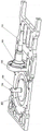
本发明公开了一种双光楔激光雷达扫描光机及扫描轨迹控制方法,双光楔激光雷达扫描光机如图1~6所示,包括机体5,机体5内设有激光入射单元1、扫描单元2、接收单元3及惯性导航单元4,机体5内还设有主控单元以及作为连接骨架的底座6。The present invention discloses a dual optical wedge laser radar scanning optical machine and a scanning track control method. The dual optical wedge laser radar scanning optical machine is shown in Figs.
激光入射单元1包括设于底座6上的入射激光固定座105,入射激光固定座105上设有激光准直器102。激光准直器102水平设置,激光准直器102侧部设有与其连接且水平设置的激光光纤101。The laser incident unit 1 includes an incident
激光准直器102具有光束准直功能,可将激光光纤101送入的大发散角脉冲激光信号准直为小束散角的脉冲光源,以保证能量集中。The
入射激光固定座105远离激光光纤101一侧设有反射镜103,反射镜103呈柱状,反射镜103顶部具有的斜面作为反射面,反射面为椭圆形,反射面与水平面呈45°夹角设置,反射镜103的反射面朝向激光准直器102。Incident
反射镜103对通过激光准直器102的入射光线进行90°偏转,反射镜103反射面的短轴等于准直后的小束散角脉冲光源光斑直径。The
反射镜103外部套设有防旁瓣套筒104,防旁瓣套筒104竖直设置。反射镜103反射面侧部的防旁瓣套筒104上设有入射口,入射口的内径,与通过入射口的激光光斑直径匹配。防旁瓣套筒104顶部设有出射口,出射口的内径,与通过出射口的激光光斑直径匹配。An
激光入射单元1采用脉冲激光器作为光源,可发射高能量脉冲激光信号,且具备连续可调的脉冲频率、脉冲能量及脉冲宽度等控制功能。The laser incident unit 1 uses a pulsed laser as a light source, can emit high-energy pulsed laser signals, and has control functions such as continuously adjustable pulse frequency, pulse energy, and pulse width.
脉冲激光器出射激光经激光光纤101进入激光准直器102,经准直后的脉冲激光入射到反射镜103的反射面上,准直后的激光仍然存在一定的旁瓣,通过防旁瓣套筒104对旁瓣进行收敛,防止旁瓣激光经漫反射后进入接收单元3。The laser output from the pulsed laser enters the
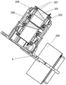
扫描单元2包括壳体208,壳体208设于入射激光固定座105侧部的底座6上,反射镜103及防旁瓣套筒104位于壳体208内底部。The
壳体208内设有两组扫描机构,扫描机构包括设于壳体208上的光楔镜筒206,光楔镜筒206通过精密轴承207转动设于壳体208上,光楔镜筒206内固定有光楔201,两组扫描机构的光楔201在竖直方向上叠加设置,使得光线穿过两光楔201。光楔201具有一定的楔角和光线折射能力,能够实现入射光线传播方向的偏转。There are two sets of scanning mechanisms inside the
壳体208上对应位置设有与光楔镜筒206配合的分体式直流电机202,机体5内设有与分体式直流电机202电性连接的伺服驱动器205,伺服驱动器205实现直流电机的精准转角和转速控制。分体式直流电机202为内转子电机,内转子与光楔镜筒206刚性连接,带动光楔镜筒206和光楔201旋转。A split-
壳体208上对应位置设有增量式角度测量传感器,提供电机旋转角度测量数据,增量式角度测量传感器包括圆光栅编码器203和圆光栅读数头204。光楔镜筒206旋转角度由圆光栅编码器203进行测量,圆光栅读数头204输出脉冲信号至主控单元和伺服驱动器205,完成角度测量和伺服闭环控制。An incremental angle measurement sensor is provided at a corresponding position on the
接收单元3包括接收安装镜筒302,接收安装镜筒302处于底座6下部的机体5内,接收安装镜筒302底部设有光电转换传感器301,接收安装镜筒302内上下设置有窄带滤光片307和非球面接收透镜306。窄带滤光片307水平位于反射镜103底部且两者连接,窄带滤光片307中心设有用于固定反射镜103的开口。The receiving unit 3 includes a receiving and installing
窄带滤光片307只允许指定波长光线通过,进而实现杂质光滤除功能,非球面接收透镜306能够实现大视野角度范围内的光线聚焦,光电转换传感器301可接收特定波长的激光信号,具有一定大小的感光靶面,能够实现光信号到电压/电流信号的转换。The narrow-
接收安装镜筒302内对应设有与非球面接收透镜306配合的接收透镜安装支撑体305,接收透镜安装支撑体305上设有与其螺纹连接的接收透镜压环304,接收透镜压环304的环面上还设有橡胶垫圈303,通过接收透镜安装支撑体305及接收透镜压环304将非球面接收透镜306固定,接收透镜压环304和接收透镜安装支撑体305构成整个非球面接收透镜306的安装结构。窄带滤光片307顶部还设有与其配合的滤光片压环308,滤光片压环308与接收透镜安装支撑体305螺纹连接。The receiver mounting
激光入射单元1中,脉冲激光器射出激光,激光经激光光纤101进入激光准直器102,激光再由反射镜103偏转后进入扫描单元2,激光通过扫描单元2的两个光楔201后射出。激光反射后进入接收单元3,返回的激光由非球面接收透镜306进行聚焦,光电转换传感器301的靶面位于非球面接收透镜306的焦点上,通过光电转换传感器301实现光信号到电压/电流信号的转换。In the laser incident unit 1, the pulse laser emits laser light, the laser light enters the
双光楔激光雷达扫描光机的扫描轨迹控制方法如下:The scanning trajectory control method of the double optical wedge lidar scanning optical machine is as follows:
通过光楔201初始相位对齐和相位控制,使不同的初始相位和相位控制实现不同的扫描脚点轨迹控制;光楔201初始相位对齐是通过两个分体式直流电机202转角的控制,实现两个光楔201不同的初始角度控制;光楔201相位控制是通过两个分体式直流电机202转动速度的控制,实现两个光楔201在连续旋转过程中不同的相对角度控制。Through the initial phase alignment and phase control of the
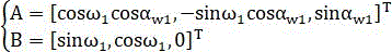
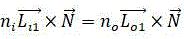
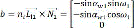
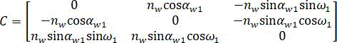
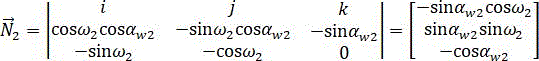
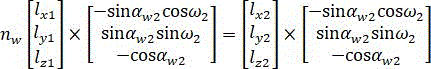
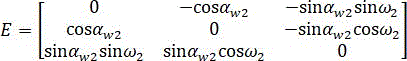
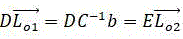
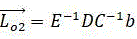
图7为简化后的双光楔对光线的折射示意图,两个光楔201分别为光楔I和光楔II,
出射光线首先经光楔I的

两个光楔201对光线的折射可描述为:The refraction of light by two
设光线沿主光轴Z入射,则入射方向向量


面
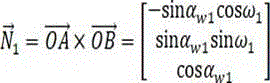
光线经面


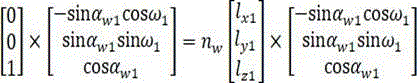
令:make:
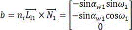
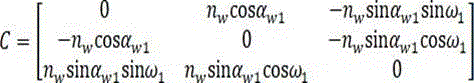
求解方程

光楔I和光楔II的两个立面平行放置,平行立面对光线的折射效果相互抵消,光楔
II的入射光线为面


注意到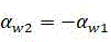


设


则


可以看出在不同的旋转角度时,扫描落点具有不同的分布方式,因此可以通过两个光楔201的不同旋转速度实现不同样式的扫描轨迹控制。It can be seen that at different rotation angles, the scanning landing points have different distribution modes, so different patterns of scanning trajectory control can be realized through different rotation speeds of the two
本发明具有的有益效果如下:The beneficial effects that the present invention has are as follows:
采用双楔形镜折射,单个光楔201偏转角达到30°,最大偏转角±30°,扫描视场大,双光楔扫描采用激光折射方式,有效减小系统的体积,可将点云全部分布在±30°的视场角范围内,光学利用率可达到100%;Double-wedge mirror refraction is adopted, the deflection angle of a
分体式直流电机202为内转子电机,转子和光楔镜筒206刚性连接,带动光楔镜筒206和光楔201旋转,可以提高设备稳定度,抗震效果好,分体式直流电机202转速快,速度可控,并由伺服驱动器205控制,实现转速和转角的精准控制,扫描速度快;The
光楔镜筒206旋转角度由圆光栅编码器203进行测量,采用高精度编码器,位置反馈角度精度高,圆光栅读数头204输出脉冲信号至主控单元和伺服驱动器205,完成角度测量和伺服闭环控制,扫描精度高;The rotation angle of the optical
传统激光雷达搭载于无人机上进行电力巡检及测绘作业时,作业效率低且作业成本高,本发明基于双光楔扫描方式实现激光脉冲全利用,提升点云利用率,本发明搭载于无人机进行快速飞行,解决了点云密度低的问题,可满足如电力巡检、测绘等高点云密度要求的应用。When the traditional laser radar is carried on the UAV for power inspection and surveying and mapping operations, the operation efficiency is low and the operation cost is high. The present invention realizes the full utilization of laser pulses based on the double optical wedge scanning method and improves the utilization rate of point clouds. The present invention is carried on the drone The fast flight of man-machine solves the problem of low point cloud density, and can meet the requirements of high point cloud density such as power inspection, surveying and mapping.
上述实施例只是本发明的较佳实施例,并不是对本发明技术方案的限制,只要是不经过创造性劳动即可在上述实施例的基础上实现的技术方案,均应视为落入本发明专利的权利保护范围内。The above-described embodiments are only preferred embodiments of the present invention, and are not limitations to the technical solutions of the present invention. As long as they are technical solutions that can be realized on the basis of the above-mentioned embodiments without creative work, they should be regarded as falling into the scope of the patent of the present invention. within the scope of protection of rights.
Claims (9)


Priority Applications (1)
| Application Number | Priority Date | Filing Date | Title |
|---|---|---|---|
| CN202211243627.0A CN115327552B (en) | 2022-10-12 | 2022-10-12 | A scanning optical machine and scanning trajectory control method of a double optical wedge lidar |
Applications Claiming Priority (1)
| Application Number | Priority Date | Filing Date | Title |
|---|---|---|---|
| CN202211243627.0A CN115327552B (en) | 2022-10-12 | 2022-10-12 | A scanning optical machine and scanning trajectory control method of a double optical wedge lidar |
Publications (2)
| Publication Number | Publication Date |
|---|---|
| CN115327552A CN115327552A (en) | 2022-11-11 |
| CN115327552B true CN115327552B (en) | 2022-12-20 |
Family
ID=83913694
Family Applications (1)
| Application Number | Title | Priority Date | Filing Date |
|---|---|---|---|
| CN202211243627.0A Active CN115327552B (en) | 2022-10-12 | 2022-10-12 | A scanning optical machine and scanning trajectory control method of a double optical wedge lidar |
Country Status (1)
| Country | Link |
|---|---|
| CN (1) | CN115327552B (en) |
Families Citing this family (1)
| Publication number | Priority date | Publication date | Assignee | Title |
|---|---|---|---|---|
| CN117428790B (en) * | 2023-12-19 | 2024-02-23 | 四川吉埃智能科技有限公司 | Robot obstacle avoidance detection device and method |
Family Cites Families (17)
| Publication number | Priority date | Publication date | Assignee | Title |
|---|---|---|---|---|
| US7248342B1 (en) * | 2003-02-14 | 2007-07-24 | United States Of America As Represented By The Administrator Of The National Aeronautics And Space Administration | Three-dimension imaging lidar |
| CN100547344C (en) * | 2007-02-07 | 2009-10-07 | 中国科学院上海光学精密机械研究所 | Sinusoidal phase modulation interferometer for real-time measurement of surface topography |
| CA3065589C (en) * | 2010-06-03 | 2022-04-26 | Catalent Ontario Limited | Multi phase soft gel capsules, apparatus and method thereof |
| CN102955251B (en) * | 2012-11-07 | 2014-10-22 | 同济大学 | Coarse and fine scanning rotating prism device |
| CN103317233B (en) * | 2013-06-07 | 2015-02-18 | 张立国 | Light beam movement track control device for laser processing |
| CN105319705B (en) * | 2015-12-02 | 2018-06-26 | 中国航空工业集团公司洛阳电光设备研究所 | A kind of double wedge scanning means and photoelectric detection equipment |
| CN106152972A (en) * | 2016-08-11 | 2016-11-23 | 广西师范大学 | A kind of phase-shift type optical projection three-dimension measuring system and method |
| CN106403846B (en) * | 2016-11-25 | 2019-07-02 | 深圳中科岹科技有限公司 | Optical projection device for three-dimensional measurement of object surface |
| CN106646859B (en) * | 2016-12-01 | 2019-03-26 | 上海航天控制技术研究所 | Double wedge optical scanners executing agency of single motor driving |
| EP3623843B1 (en) * | 2018-09-11 | 2021-01-13 | Leica Geosystems AG | Hand-held laser range finder |
| CN110695523B (en) * | 2019-06-19 | 2021-01-15 | 西安中科微精光子制造科技有限公司 | Laser scanning device |
| CN111123507B (en) * | 2019-11-28 | 2022-02-08 | 武汉华中天经通视科技有限公司 | Synchronous scanning rotating double-prism device and one-dimensional scanning method thereof |
| CN111288923A (en) * | 2020-04-02 | 2020-06-16 | 四川文理学院 | Multimodal laser scanner optomechanical system and equipment |
| CN112462512B (en) * | 2020-11-11 | 2022-11-22 | 山东科技大学 | Airborne lidar scanning mirror device, system and scanning method |
| CN114624675A (en) * | 2020-12-10 | 2022-06-14 | 北醒(北京)光子科技有限公司 | Laser radar and scanning method thereof |
| CN113534190B (en) * | 2021-06-22 | 2024-07-09 | 深圳玩智商科技有限公司 | Three-dimensional laser radar imaging system and method based on double optical wedges |
| CN113673078B (en) * | 2021-07-14 | 2024-03-19 | 南京航空航天大学 | A simulation calculation method of double-wedge lidar |
-
2022
- 2022-10-12 CN CN202211243627.0A patent/CN115327552B/en active Active
Also Published As
| Publication number | Publication date |
|---|---|
| CN115327552A (en) | 2022-11-11 |
Similar Documents
| Publication | Publication Date | Title |
|---|---|---|
| US11782131B2 (en) | 2D scanning high precision LiDAR using combination of rotating concave mirror and beam steering devices | |
| US11336074B2 (en) | LIDAR sensor system with small form factor | |
| CN111263897B (en) | Distance detection device | |
| CN110325877B (en) | System and method for supporting lidar applications | |
| CN110235025B (en) | Distance detecting device | |
| KR102887305B1 (en) | Laser radar system and its control method, method for obtaining scan angle and vehicle | |
| CN107450060B (en) | Laser scanning device | |
| CN107037444A (en) | Optical system and laser radar | |
| CN113126061A (en) | Laser radar and scanning method thereof | |
| CN108387908A (en) | Laser radar optical texture and laser radar apparatus | |
| CN115754986A (en) | Laser radar optical scanning system, laser radar and aircraft | |
| CN115327552B (en) | A scanning optical machine and scanning trajectory control method of a double optical wedge lidar | |
| CN113030911A (en) | Laser radar system | |
| US20230341677A1 (en) | Optical assembly for scanning lidar system | |
| CN1560563A (en) | A laser collimation system and collimation method for automatically measuring light drift angle | |
| CN206546432U (en) | A kind of laser radar optical system based on time flight method | |
| CN208737000U (en) | A kind of four sides revolving mirror laser radar | |
| CN108627983B (en) | Laser beam combining system and beam combining method thereof | |
| CN212275968U (en) | Laser radar system | |
| US11796385B2 (en) | Optical receiving device and optical sensing device comprising a reflecting surface having a second portion arranged along an outer boundary of a first portion with different reflectivity | |
| CN115951329A (en) | A MEMS laser radar optical collimation ring scanning device and method | |
| CN113030913A (en) | Laser radar device and system based on two-dimensional galvanometer | |
| CN112462512B (en) | Airborne lidar scanning mirror device, system and scanning method | |
| CN220178453U (en) | A laser scanning optical system and portable laser welding equipment | |
| CN113534190A (en) | Three-dimensional laser radar imaging system and method based on double optical wedges |
Legal Events
| Date | Code | Title | Description |
|---|---|---|---|
| PB01 | Publication | ||
| PB01 | Publication | ||
| SE01 | Entry into force of request for substantive examination | ||
| SE01 | Entry into force of request for substantive examination | ||
| GR01 | Patent grant | ||
| GR01 | Patent grant | ||
| EE01 | Entry into force of recordation of patent licensing contract | ||
| EE01 | Entry into force of recordation of patent licensing contract |
Application publication date: 20221111 Assignee: Sichuan Xianwei Intelligent Equipment Co.,Ltd. Assignor: Sichuan ji'e Intelligent Technology Co.,Ltd. Contract record no.: X2024980035816 Denomination of invention: A Dual Wedge Lidar Scanning Machine and Scanning Trajectory Control Method Granted publication date: 20221220 License type: Common License Record date: 20241213 |