CN115274349A - Magnetic control circuit breaker on primary and secondary deep fusion complete column - Google Patents
Magnetic control circuit breaker on primary and secondary deep fusion complete column Download PDFInfo
- Publication number
- CN115274349A CN115274349A CN202211065014.2A CN202211065014A CN115274349A CN 115274349 A CN115274349 A CN 115274349A CN 202211065014 A CN202211065014 A CN 202211065014A CN 115274349 A CN115274349 A CN 115274349A
- Authority
- CN
- China
- Prior art keywords
- circuit breaker
- magnetic control
- switching
- separating brake
- synchronizing shaft
- Prior art date
- Legal status (The legal status is an assumption and is not a legal conclusion. Google has not performed a legal analysis and makes no representation as to the accuracy of the status listed.)
- Pending
Links
Images


Classifications
-
- H—ELECTRICITY
- H01—ELECTRIC ELEMENTS
- H01H—ELECTRIC SWITCHES; RELAYS; SELECTORS; EMERGENCY PROTECTIVE DEVICES
- H01H33/00—High-tension or heavy-current switches with arc-extinguishing or arc-preventing means
- H01H33/60—Switches wherein the means for extinguishing or preventing the arc do not include separate means for obtaining or increasing flow of arc-extinguishing fluid
- H01H33/66—Vacuum switches
- H01H33/662—Housings or protective screens
-
- H—ELECTRICITY
- H01—ELECTRIC ELEMENTS
- H01H—ELECTRIC SWITCHES; RELAYS; SELECTORS; EMERGENCY PROTECTIVE DEVICES
- H01H33/00—High-tension or heavy-current switches with arc-extinguishing or arc-preventing means
- H01H33/02—Details
-
- H—ELECTRICITY
- H01—ELECTRIC ELEMENTS
- H01H—ELECTRIC SWITCHES; RELAYS; SELECTORS; EMERGENCY PROTECTIVE DEVICES
- H01H33/00—High-tension or heavy-current switches with arc-extinguishing or arc-preventing means
- H01H33/02—Details
- H01H33/28—Power arrangements internal to the switch for operating the driving mechanism
- H01H33/38—Power arrangements internal to the switch for operating the driving mechanism using electromagnet
-
- H—ELECTRICITY
- H01—ELECTRIC ELEMENTS
- H01H—ELECTRIC SWITCHES; RELAYS; SELECTORS; EMERGENCY PROTECTIVE DEVICES
- H01H33/00—High-tension or heavy-current switches with arc-extinguishing or arc-preventing means
- H01H33/60—Switches wherein the means for extinguishing or preventing the arc do not include separate means for obtaining or increasing flow of arc-extinguishing fluid
- H01H33/66—Vacuum switches
- H01H33/666—Operating arrangements
Landscapes
- Physics & Mathematics (AREA)
- Electromagnetism (AREA)
- Driving Mechanisms And Operating Circuits Of Arc-Extinguishing High-Tension Switches (AREA)
Abstract
The invention discloses a primary and secondary depth fusion set column upper magnetic control circuit breaker which reduces the failure rate, improves the reliability, reduces the installation difficulty and has secondary control. The automatic terminal device comprises an automatic terminal device and a breaker shell which are installed on a tower, wherein three solid-sealed polar columns are arranged on the breaker shell, a synchronizing shaft assembly and three magnetic control mechanisms which are connected with the synchronizing shaft assembly are arranged in the breaker shell, the lower ends of the interiors of the three solid-sealed polar columns are respectively fixed in the three magnetic control mechanisms, a separation and combination indicating device connected with the synchronizing shaft assembly is arranged at the outer end of the breaker shell, a magnetic controller is arranged in the automatic terminal device and is electrically connected with the three magnetic control mechanisms, an electricity taking capacitor is fixedly sealed in the solid-sealed polar columns, and the electricity taking capacitor is connected with the automatic terminal device through an electric wire. The pole-mounted switch is applied to the technical field of overhead line pole-mounted switches of power distribution networks.
Description
Technical Field
The invention relates to a magnetic control circuit breaker, in particular to a magnetic control circuit breaker on a primary and secondary deep fusion complete set column.
Background
A secondary fusion complete set of circuit breaker equipment is on-pole complete set of circuit breaker equipment which fuses advanced technologies such as leading voltage sensors, current sensors, electric energy metering modules, high-speed fault transient recording and the like in the industry. The complete equipment can realize the function of self-adaptive comprehensive type on-site automation without depending on a distribution automation main station and communication, realizes on-site line selection, area positioning and isolation of single-phase earth faults by control logics such as a short circuit/earth fault detection technology, non-voltage switching-off, fault path self-adaptive delay incoming call switching-on and the like, realizes the power supply of fault area isolation and non-fault area recovery by twice reclosing, and is a preferred product of distribution automation.
At present, a switching-on and switching-off mechanism used by a pole-mounted circuit breaker is a spring mechanism, the number of parts of the mechanism is large, and the abnormal problems of mechanism clamping stagnation and the like caused by multi-stage transmission of the spring mechanism cause high failure rate of the mechanism and are troublesome to install and debug the mechanism.
At present, an automatic terminal unit (FTU) of the pole-mounted circuit breaker has high power consumption and can only supply power through an external voltage transformer, and the external voltage transformer has large volume and large installation difficulty on a pole tower.
At present, the on-column circuit breaker is controlled to be switched on and switched off only through a switching-on and switching-off switch, a secondary control part is not provided, and the switching-on and switching-off regulation and control function is single.
Disclosure of Invention
The invention aims to solve the technical problem of overcoming the defects of the prior art and provides a primary and secondary depth fusion set column upper magnetic control circuit breaker which has the advantages of reducing the failure rate, improving the reliability, reducing the installation difficulty and having secondary control.
The technical scheme adopted by the invention is as follows: the automatic terminal device comprises an automatic terminal device and a breaker shell, wherein the automatic terminal device and the breaker shell are installed on a tower, three solid-sealed polar columns are arranged on the breaker shell, a synchronizing shaft assembly and three magnetic control mechanisms which are connected with the synchronizing shaft assembly are arranged inside the breaker shell, the lower ends of the interiors of the three solid-sealed polar columns are respectively fixed in the three magnetic control mechanisms, a separation and combination indicating device connected with the synchronizing shaft assembly is arranged at the outer end of the breaker shell, a magnetic controller is arranged in the automatic terminal device and electrically connected with the three magnetic control mechanisms, an electricity taking capacitor is fixedly sealed in the solid-sealed polar columns, and the electricity taking capacitor is connected with the automatic terminal device through an electric wire.
Further, gu seal utmost point post and include utmost point post body, vacuum interrupter, electrically conductive clamp, flexible coupling, connector, insulating pull rod, adjusting head, conducting rod, inlet wire binding post and the binding post that is qualified for the next round of competitions, this internal inner chamber that is equipped with of utmost point post, vacuum interrupter install in the upper end of inner chamber, just the quiet end of vacuum interrupter is worn out the inner chamber is fixed in through the nut the top of utmost point post body, inlet wire binding post install in on the quiet end of vacuum interrupter, the end that moves of vacuum interrupter passes electrically conductive clamp to be fixed in through the bolt on the end that moves of vacuum interrupter, the one end of flexible coupling with electrically conductive clamp is connected, the conducting rod is fixed in through the nut the leading-out terminal of utmost point post body, the other end of flexible coupling with the one end of conducting rod passes through threaded connection, the other end of conducting rod with binding post is connected, the one end of connector with the end that moves of vacuum interrupter is connected, the other end of connector passes the flexible coupling with the upper end of insulating pull rod is connected, the lower part of insulating pull rod with the adjusting head is fixed in through the lower extreme of magnetic control mechanism.
Furthermore, a mounting plate is arranged inside the shell of the circuit breaker, the magnetic control mechanisms are all mounted on the mounting plate, each magnetic control mechanism comprises a static iron core, a movable iron core, a switching-on and switching-off coil, a switching-off spring, an overtravel spring and a fixing piece, the static iron core is mounted on the mounting plate, the movable iron core is mounted on the fixing piece, the fixing piece is connected with the synchronous shaft assembly, a magnet controller is arranged in the static iron core and wound with the switching-on and switching-off coil, the switching-off spring is located between the static iron core and the movable iron core, and the overtravel spring is arranged inside the switching-off spring; the tail end of the insulation adjusting pull rod sequentially penetrates through the mounting plate, the static iron core, the separating brake spring, the movable iron core and the fixed sheet and is fixed at the lower end of the fixed sheet through a flange hexagonal nut, and the adjusting head is used for adjusting compression of the stroke of the over travel spring.
Furthermore, this internal electronic type voltage sensor and electronic type current sensor that still seals admittedly of utmost point post, electronic type current sensor seals admittedly and installs the side of being qualified for the next round of competitions at utmost point post body, electronic type voltage sensor seals admittedly and installs the incoming line side or the side of being qualified for the next round of competitions of utmost point post body, get electric condenser and seal admittedly and install the side of being qualified for the next round of competitions of utmost point post body, seal admittedly and install and make electronic type voltage sensor, electronic type current sensor and get electric condenser and outside steam, corrosive environment completely isolated to increase life.
Furthermore, the synchronizing shaft assembly including install in the installation cover of the inside both sides of circuit breaker casing, all install the bearing in the installation cover, two install the synchronizing shaft between the bearing, the lower extreme both sides of stationary blade all are provided with fixed ear, be provided with on the synchronizing shaft with the connection piece that fixed ear is connected, the connection piece with fixed ear is fixed mutually through the cylinder round pin.
Furthermore, the on-off indicating device comprises an on-off indicating needle, an on-off shaft sleeve, an on-off connecting shaft, a shifting fork and an on-off connecting rod, wherein the on-off connecting shaft is fixed on the end face of the circuit breaker shell through the on-off shaft sleeve, one end of the on-off connecting shaft is connected with the on-off indicating needle, the other end of the on-off connecting shaft extends into the pole body and is connected with the shifting fork, the on-off connecting rod is connected with the synchronizing shaft, and an on-off column located in the shifting fork is arranged at the tail end of the on-off connecting rod.
Further, the terminal surface of circuit breaker casing still is provided with urgent separating brake device, urgent separating brake device includes separating brake handle, separating brake axle sleeve, separating brake even axle, separating brake connecting rod and reset spring, the separating brake even axle is fixed in through the separating brake axle sleeve on the terminal surface of circuit breaker casing, just the one end of separating brake even axle is connected with the separating brake handle, the other end of separating brake even axle stretches into this internal and with reset spring's one end is connected, reset spring's the other end is fixed in on the terminal surface of circuit breaker casing through the pin post, separating brake connecting rod with the synchronizing shaft is connected, separating brake connecting rod's end with the end of separating brake even axle is connected.
Furthermore, auxiliary switch briquetting is still installed at the both ends of synchronizing shaft, about the two inside walls of circuit breaker casing all establish with the auxiliary switch of auxiliary switch briquetting looks adaptation, clockwise or anticlockwise rotation of synchronizing shaft drives the auxiliary switch briquetting, and the auxiliary switch briquetting can be pushed down or not pushed down the auxiliary switch, and the auxiliary switch output is for doing the node signal.
Furthermore, an FTU controller and a backup power supply are arranged in the automatic terminal device, the backup power supply is electrically connected with the FTU controller, and the FTU controller is used for remote control, remote measurement, remote signaling and fault detection functions; the magnetic controller comprises a power supply management system, a main module and a discharging loop, wherein a charging management system is arranged in the power supply management system and used for charging management and protection management, after charging is completed, a switching-on or switching-off command and a position signal are input through the outside, the main module performs operation and outputs the switching-on or switching-off command, and the discharging loop outputs voltage to control the switching-on and switching-off of the magnetic control mechanism.
Further, the circuit breaker casing is formed by welding after the stainless steel is bent, the lug is welded to the outside of circuit breaker casing, the handle is welded to the both sides limit of circuit breaker casing, the inboard of circuit breaker casing is provided with the sealing strip.
The beneficial effects of the invention are: 1. the magnetic control mechanism is used for replacing the spring mechanism, so that the abnormal problems of mechanism clamping stagnation and the like caused by multi-stage transmission of the spring mechanism can be avoided, the integral reliability is improved, and the operation state perception of equipment is facilitated; 2. an electricity-taking capacitor is fixedly sealed in the solid-sealed polar pole, and an output power supply of the electricity-taking capacitor can directly supply power to the low-power-consumption automatic terminal device, so that the installation difficulty of installing a voltage transformer is avoided; 3. the automatic terminal device is internally provided with a magnetic controller, and the magnetic controller changes an electromagnetic field in the magnetic control mechanism through a capacitance charging and discharging principle to realize the opening and closing action of the magnetic control mechanism after receiving a closing/opening command of the automatic terminal device, so that a secondary control part can be formed.
Drawings
FIG. 1 is a schematic view of the present invention mounted on a tower;
fig. 2 is a schematic structural view of a circuit breaker housing;
FIG. 3 is a schematic view of the structure of an automated terminal device;
figure 4 is a front view of the circuit breaker housing after opening the enclosure;
fig. 5 is a first bottom view of the circuit breaker housing;
fig. 6 is a second bottom view of the circuit breaker housing;
FIG. 7 is a view showing the installation structure between the embedded pole and the magnetic control mechanism;
figure 8 is a schematic view of the embedded pole mounted in the circuit breaker housing;
FIG. 9 isbase:Sub>A sectional view taken along line A-A of FIG. 7;
FIG. 10 is an enlarged schematic view of the portion of FIG. 8B;
FIG. 11 is an enlarged schematic view of the portion of FIG. 9C;
fig. 12 is a bottom view of the embedded pole;
FIG. 13 is a cross-sectional view taken in the direction of E-E of FIG. 12;
FIG. 14 is a cross-sectional view of a magnetic control mechanism;
fig. 15 is a schematic diagram of the secondary control portion.
Detailed Description
As shown in fig. 1 to 15, in this embodiment, the present invention includes an automatic terminal device 2 and a circuit breaker housing 3 installed on a tower 1, the circuit breaker housing 3 is provided with three embedded poles 4, the three embedded poles 4 are three-phase poles, a synchronizing shaft assembly 5 and three magnetic control mechanisms 6 connected to the synchronizing shaft assembly 5 are arranged inside the circuit breaker housing 3, lower ends inside the three embedded poles 4 are respectively fixed inside the three magnetic control mechanisms 6, an opening and closing indication device 7 connected to the synchronizing shaft assembly 5 is arranged at an outer end of the circuit breaker housing 3, a magnetic controller is arranged inside the automatic terminal device 2, the magnetic controller is electrically connected to the three magnetic control mechanisms 6, an electricity-taking capacitor 8 is embedded inside the embedded poles 4, the electricity-taking capacitor 8 is electrically connected to the automatic terminal device 2, in this embodiment, the automatic terminal device 2 used for on-pole switching is a low-power consumption terminal, the maximum power is not more than 6W, the electricity-taking capacitor 8 can output a 15W dc power source, so that the electricity-taking capacitor 8 can directly supply power to the terminal device 2, no additional voltage transformer is required, and the overall construction difficulty of the post is reduced.
In this embodiment, the embedded pole 4 includes a pole body 41, a vacuum interrupter 42, a conductive clip 43, a flexible connection 44, a connector 45, an insulating pull rod 46, an adjusting head 47, a conductive rod 48, a wire inlet connection terminal 49 and a wire outlet connection terminal 410, an inner cavity 411 is provided in the pole body 41, the vacuum interrupter 42 is installed at the upper end of the inner cavity 411, a static end of the vacuum interrupter 42 penetrates out of the inner cavity 411 and is fixed to the top of the pole body 41 through a nut, the wire inlet connection terminal 49 is installed at the static end of the vacuum interrupter 42, a dynamic end of the vacuum interrupter 42 penetrates through the conductive clip 43 and is fixed to the dynamic end of the vacuum interrupter 42 through a bolt, one end of the flexible connection 44 is connected to the conductive clip 43, the conductive rod 48 is fixed to a wire outlet end of the pole body 41 through a nut, the other end of the flexible connection 44 is in threaded connection with one end of the conductive rod 48, the other end of the conductive rod 48 is connected to the wire outlet connection terminal 410, one end of the connector 45 is connected to the dynamic end of the vacuum interrupter 42, the other end of the flexible connection 44 is connected to the insulating pull rod 46, and the insulating pull rod 6 is fixed to the insulating pull rod 46 through a lower end of the insulating pull rod mechanism 46; the insulating material that insulating pull rod 46 used is the nylon materials, and the creepage distance who designs insulating pull rod 46 structure reaches 249mm, satisfies air insulating properties under 10kV voltage class completely.
In this embodiment, a mounting plate 31 is arranged inside the circuit breaker housing 3, the magnetic control mechanisms 6 are all mounted on the mounting plate 31, the design is convenient for later-stage overall disassembly and assembly, the magnetic control mechanism 6 comprises a static iron core 61, a movable iron core 62, a switching-off and switching-on coil 63, a switching-off spring 64, an over travel spring 65 and a fixing plate 66, the number of parts of the whole magnetic control mechanism 6 is small, the failure rate is reduced, the static iron core 61 is mounted on the mounting plate 31, the movable iron core 62 is mounted on the fixing plate 66, the fixing plate 66 is connected with the synchronous shaft assembly 5, a magnet controller is arranged in the static iron core 61 and wound with the switching-off and switching-on coil 63, the switching-off spring 64 is located between the static iron core 61 and the movable iron core 62, and the over travel spring 65 is arranged inside the switching-off spring 64; the end of the insulating pull rod 46 passes through the mounting plate 31 in proper order the quiet iron core 61 the separating brake spring 64 move the iron core 62 with the stationary blade 66 to be fixed in through flange hexagonal nut 461 the lower extreme of stationary blade 66, adjust in the head 47 stretches into the separating brake spring 64, support the over travel spring 65, can adjust the head 47 moves down, thereby adjusts the compression the over travel spring 65 is in the quiet iron core 61 with move the 62 strokes of iron core.
Furthermore, the distance between the upper end surface of the adjusting head 47 on the insulating pull rod 46 and the top surface of the circuit breaker housing 3 is adjusted to be L, that is, the distance that the adjusting head 47 presses the over travel spring 65 downwards is mainly used for ensuring that the elastic force provided by the compression of the over travel spring 65 inside the magnetic control mechanism 6 is matched with the contact pressure of the vacuum arc-extinguishing chamber 42 when the magnetic control mechanism 6 is in a closing state; the three solid-sealed polar columns 4 are completely assembled with the three magnetic control mechanisms 6 according to the same method; finally, the fixing plate 66 is installed on the upper portion of the magnetic control mechanism, the flange hexagon nut 461 is screwed on the tail end of the insulating pull rod 46, the distance D between the lower end face of the flange hexagon nut 461 and the upper end face of the fixing plate is guaranteed, the distance is the overtravel of the vacuum arc-extinguishing chamber 42, the overtravel can be changed by changing the distance, and the total movement stroke of the magnetic control mechanism 6 is unchanged, so that the opening distance of the vacuum arc-extinguishing chamber 42 is changed while the overtravel is changed.
In this embodiment, an electronic voltage sensor 412 and an electronic current sensor 413 are further embedded in the pole body 41, the electronic current sensor 413 is embedded in the outlet side of the pole body 41, the electronic voltage sensor 412 is embedded in the inlet side or the outlet side of the pole body 41, and the power-taking capacitor 8 is embedded in the outlet side of the pole body 41; secondary output analog quantity small signals of the electronic voltage sensor 412 and the electronic current sensor 413 are used for measurement or protection; the power-taking capacitor 8 outputs a rated voltage of 27V and a rated power of 15W, and can directly supply power to the low-power consumption controller FTU, the electronic voltage sensor 412 does not contain an iron core or a light-load small iron core, and cannot be saturated, the frequency response range is wide, the measurement range is large, the linearity is good, and the protection device can reliably act in a system fault state; overcurrent and ferromagnetic resonance can not be generated when the voltage output end is in a secondary short circuit, so that major fault hidden danger in the operation of a power system is eliminated, and the safety of personnel and equipment is guaranteed; in addition, the electronic current sensor 412 is a high-quality element Wen Piaoxiao and has strong weather resistance; the small signal output is simulated, the power consumption is low, and the loading capacity meets the requirements of the automatic terminal device 2.
In this embodiment, the synchronizing shaft assembly 5 includes an installation sleeve 51 installed on two sides inside the circuit breaker housing 3, bearings 52 are installed in the installation sleeve 51, two synchronizing shafts 53 are installed between the bearings 52, fixing lugs 661 are provided on two sides of the lower end of the fixing piece 66, a connecting piece 55 connected to the fixing lugs 661 is provided on the synchronizing shaft 53, the connecting piece 55 is fixed to the fixing lugs 661 through a cylindrical pin 56, this design ensures that three-phase opening can be performed through the synchronizing shafts 53 during opening, specifically, the fixing lugs in three magnetic control mechanisms 6 are driven to move by rotation of the synchronizing shafts 53, so that the fixing piece 66 drives the movable iron core 62 to move down, the opening spring 64 between the stationary iron core 61 and the movable iron core 62 is compressed, and the electromagnetic field in the magnetic control mechanisms 6 is changed to realize opening and closing actions of the magnetic control mechanisms.
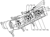
In this embodiment, the switching indicator 7 includes a switching indicator 71, a switching sleeve 72, a switching shaft 73, a fork 74, and a switching link 75, where the switching shaft 73 is fixed to the end surface of the circuit breaker housing 3 through the switching sleeve 72, one end of the switching shaft 73 is connected to the switching indicator 71, the other end of the switching shaft 73 extends into the pole body 41 and is connected to the fork 74, the switching link 75 is connected to the synchronizing shaft 53, and a switching post 76 located in the fork 74 is provided at the end of the switching link 75.
In this embodiment, the end surface of the circuit breaker housing 3 is further provided with an emergency opening device 9, the emergency opening device 9 includes an opening handle 91, an opening shaft sleeve 92, an opening connecting shaft 93, an opening connecting rod 94 and a return spring 95, the opening connecting shaft 93 is fixed on the end surface of the circuit breaker housing 3 through the opening shaft sleeve 92, one end of the opening connecting shaft 93 is connected with the opening handle 91, the other end of the opening connecting shaft 93 extends into the pole body 41 and is connected with one end of the return spring 95, the other end of the return spring 95 is fixed on the end surface of the circuit breaker housing 3 through a pin column, the opening connecting rod 94 is connected with the synchronizing shaft 53, and the tail end of the opening connecting rod 94 is connected with the tail end of the opening connecting shaft 93; in case of emergency, the magnetic control mechanism 6 can be switched off by directly pulling downwards and rotating the switching-off handle 91 clockwise, and after switching-off is completed, the switching-off handle 91 is released and returns to the initial position through the return spring 95.
In this embodiment, the two ends of the synchronizing shaft 53 are further provided with an auxiliary switch pressing block 57, the two inner side walls of the circuit breaker housing 3 are respectively provided with an auxiliary switch 58 which is matched with the auxiliary switch pressing block 57 in a left-right mode, the synchronizing shaft 53 rotates clockwise or anticlockwise to drive the auxiliary switch pressing block 57, the auxiliary switch pressing block 57 can press or not press the auxiliary switch 58, and the auxiliary switch 58 outputs a dry node signal.
In this embodiment, the automatic terminal device 2 is further internally provided with an FTU controller and a backup power supply, the power supply part has two modes of external power supply and lithium battery power supply, the external power supply is converted into a power supply used by the FTU controller and the magnetic controller through a power-taking capacitor 8, the lithium battery power supply is used as the backup power supply, the backup power supply is electrically connected with the FTU controller, and the FTU controller is used for remote control, remote measurement, remote signaling and fault detection; the magnetic controller comprises a power management system, a main module and a discharging loop, wherein a charging management system is arranged in the power management system and used for charging management and protection management, after charging is completed, the main module performs operation and outputs a closing or opening instruction through external closing or opening instruction and position signal input, and the discharging loop outputs voltage to change an electromagnetic field in the magnetic control mechanism 6 to realize opening and closing actions of the magnetic control mechanism.
In this embodiment, circuit breaker casing 3 is bent by the stainless steel and is welded and form, 3 protection levels of circuit breaker casing can reach IP67, can the absolute protection the components and parts life of installation in the circuit breaker casing 3, the outside welding of circuit breaker casing 3 has lug 32, the both sides limit welding of circuit breaker casing 3 has handle 33, the inboard of circuit breaker casing 3 is provided with the sealing strip.
The pole-mounted switch is applied to the technical field of overhead line pole-mounted switches of power distribution networks.
While the embodiments of the present invention have been described in terms of practical embodiments, they are not to be construed as limiting the meaning of the present invention, and modifications of the embodiments and combinations with other embodiments will be apparent to those skilled in the art in light of the present description.
Claims (10)
1. The utility model provides a magnetic control circuit breaker on secondary degree of depth fusion kit post which characterized in that: it is including installing automatic terminal device (2) and circuit breaker casing (3) on shaft tower (1), be provided with three solid utmost point post (4) that seals on circuit breaker casing (3), circuit breaker casing (3) inside be provided with synchronizing shaft subassembly (5) and three all with magnetic control mechanism (6) that synchronizing shaft subassembly (5) are connected, three gu seal the inside lower extreme of utmost point post (4) and be fixed in three respectively in magnetic control mechanism (6), the outer end of circuit breaker casing (3) be provided with deciliter indicating device (7) that synchronizing shaft subassembly (5) are connected, automatic terminal device (2) embeds there is the magnetic controller, the magnetic controller is with three magnetic control mechanism (6) electricity is all connected, gu seal in utmost point post (4) admittedly have and get electric capacitor (8), get electric capacitor (8) with automatic terminal device (2) connection of electric wire.
2. The primary and secondary deep fusion set column magnetic control circuit breaker according to claim 1, characterized in that: the solid-sealed pole (4) comprises a pole body (41), a vacuum arc-extinguishing chamber (42), a conductive clamp (43), a flexible connection (44), a connector (45), an insulating pull rod (46), an adjusting head (47), a conductive rod (48), an incoming line wiring terminal (49) and an outgoing line wiring terminal (410), an inner cavity (411) is arranged in the pole body (41), the vacuum arc-extinguishing chamber (42) is installed at the upper end of the inner cavity (411), the static end of the vacuum arc-extinguishing chamber (42) penetrates out the inner cavity (411) and is fixed on the top of the pole body (41) through a nut, the incoming line wiring terminal (49) is installed at the static end of the vacuum arc-extinguishing chamber (42), the moving end of the vacuum arc-extinguishing chamber (42) penetrates through the conductive clamp (43) and is fixed on the moving end of the vacuum arc-extinguishing chamber (42) through a bolt, one end of the flexible connection (44) is connected with the conductive clamp (43), the conductive rod (48) is connected with the outgoing line terminal (48) through a screw thread (48), and one end of the movable end of the conductive rod (42) is connected with the outgoing line wiring terminal (410), the other end of the connector (45) penetrates through the flexible connection (44) and is connected with the upper end of the insulating pull rod (46), the lower portion of the insulating pull rod (46) is fixedly connected with the adjusting head (47) through threads, and the tail end of the insulating pull rod (46) penetrates through the magnetic control mechanism (6) and is fixed to the lower end of the magnetic control mechanism (6) through a nut.
3. The primary and secondary deep fusion set column magnetic control circuit breaker according to claim 2, characterized in that: the breaker is characterized in that a mounting plate (31) is arranged inside the breaker shell (3), the magnetic control mechanisms (6) are mounted on the mounting plate (31), each magnetic control mechanism (6) comprises a static iron core (61), a movable iron core (62), a switching-off coil (63), a switching-off spring (64), an over-travel spring (65) and a fixing plate (66), the static iron cores (61) are mounted on the mounting plate (31), the movable iron cores (62) are mounted on the fixing plates (66), the fixing plates (66) are connected with the synchronous shaft assembly (5), magnet control is arranged in the static iron cores (61) and wound with the switching-off coil (63), the switching-off springs (64) are located between the static iron cores (61) and the movable iron cores (62), and the over-travel springs (65) are arranged inside the switching-off springs (64); the end of insulating pull rod (46) passes in proper order mounting panel (31), quiet iron core (61) separating brake spring (64) movable iron core (62) with stationary blade (66) to be fixed in through flange hexagon nut (461) the lower extreme of stationary blade (66), just adjust head (47) and be used for adjusting the compression the stroke of overtravel spring (65).
4. The primary and secondary deep fusion set column magnetic control circuit breaker according to claim 2, characterized in that: still sealed admittedly in utmost point post body (41) have electronic type voltage sensor (412) and electronic type current sensor (413), electronic type current sensor (413) are sealed admittedly and are installed the side of being qualified for the next round of competitions at utmost point post body (41), electronic type voltage sensor (412) are sealed admittedly and are installed the inlet wire side or the side of being qualified for the next round of competitions of utmost point post body (41), it installs to get electric capacitor (8) and seal admittedly the side of being qualified for the next round of competitions of utmost point post body (41).
5. The primary and secondary deep fusion set column magnetic control circuit breaker according to claim 3, characterized in that: synchronizing shaft subassembly (5) including install in installation cover (51) of the inside both sides of circuit breaker casing (3), all install bearing (52), two in installation cover (51) install synchronizing shaft (53) between bearing (52), the lower extreme both sides of stationary blade (66) all are provided with fixed ear (661), be provided with on synchronizing shaft (53) with connection piece (55) that fixed ear (661) are connected, connection piece (55) with fixed ear (661) are fixed mutually through cylindric lock (56).
6. The primary-secondary deep-fusion column-mounted magnetic control circuit breaker according to claim 5, characterized in that: the on-off indicating device (7) comprises an on-off indicating needle (71), an on-off shaft sleeve (72), an on-off connecting shaft (73), a shifting fork (74) and an on-off connecting rod (75), the on-off connecting shaft (73) is fixed on the end face of the circuit breaker shell (3) through the on-off shaft sleeve (72), one end of the on-off connecting shaft (73) is connected with the on-off indicating needle (71), the other end of the on-off connecting shaft (73) extends into the pole body (41) and is connected with the shifting fork (74), the on-off connecting rod (75) is connected with the synchronizing shaft (53), and the tail end of the on-off connecting rod (75) is provided with an on-off column (76) located in the shifting fork (74).
7. The primary and secondary deep fusion set column magnetic control circuit breaker of claim 6, wherein: the terminal surface of circuit breaker casing (3) still is provided with urgent separating brake device (9), urgent separating brake device (9) are including separating brake handle (91), separating brake axle sleeve (92), separating brake even axle (93), separating brake connecting rod (94) and reset spring (95), separating brake even axle (93) are fixed in through separating brake axle sleeve (92) on the terminal surface of circuit breaker casing (3), just the one end of separating brake even axle (93) is connected with separating brake handle (91), the other end of separating brake even axle (93) stretches into in utmost point post body (41) and with the one end of reset spring (95) is connected, the other end of reset spring (95) is fixed in on the terminal surface of circuit breaker casing (3) through the pin post, separating brake connecting rod (94) with synchronizing shaft (53) are connected, the end of separating brake connecting rod (94) with the end of separating brake even axle (93) is connected.
8. The primary and secondary deep fusion set column magnetic control circuit breaker according to claim 5, characterized in that: auxiliary switch briquetting (57) are still installed at the both ends of synchronizing shaft (53), about two inside walls of circuit breaker casing (3) all establish with auxiliary switch (58) of auxiliary switch briquetting (57) looks adaptation, synchronizing shaft (53) clockwise or anticlockwise rotation drive auxiliary switch briquetting (57), and auxiliary switch briquetting (57) can be pushed down or not push down auxiliary switch (58), and auxiliary switch (58) output is dry node signal.
9. The primary and secondary deep fusion set column magnetic control circuit breaker according to claim 1, characterized in that: the automatic terminal device (2) is also internally provided with an FTU controller and a backup power supply, the backup power supply is electrically connected with the FTU controller, and the FTU controller is used for remote control, remote measurement, remote signaling and fault detection functions; the magnetic controller comprises a power supply management system, a main module and a discharging loop, wherein a charging management system is arranged in the power supply management system and used for charging management and protection management, after charging is completed, a switching-on or switching-off command and a position signal are input through the outside, the main module performs operation and outputs the switching-on or switching-off command, and the discharging loop outputs voltage to control the switching-on and switching-off of the magnetic control mechanism (6).
10. The primary and secondary deep fusion set column magnetic control circuit breaker according to claim 1, characterized in that: the circuit breaker casing (3) are bent by the stainless steel and are welded, lifting lugs (32) are welded on the outer side of the circuit breaker casing (3), handles (33) are welded on two side edges of the circuit breaker casing (3), and sealing strips are arranged on the inner side of the circuit breaker casing (3).
Priority Applications (1)
| Application Number | Priority Date | Filing Date | Title |
|---|---|---|---|
| CN202211065014.2A CN115274349A (en) | 2022-09-01 | 2022-09-01 | Magnetic control circuit breaker on primary and secondary deep fusion complete column |
Applications Claiming Priority (1)
| Application Number | Priority Date | Filing Date | Title |
|---|---|---|---|
| CN202211065014.2A CN115274349A (en) | 2022-09-01 | 2022-09-01 | Magnetic control circuit breaker on primary and secondary deep fusion complete column |
Publications (1)
| Publication Number | Publication Date |
|---|---|
| CN115274349A true CN115274349A (en) | 2022-11-01 |
Family
ID=83755079
Family Applications (1)
| Application Number | Title | Priority Date | Filing Date |
|---|---|---|---|
| CN202211065014.2A Pending CN115274349A (en) | 2022-09-01 | 2022-09-01 | Magnetic control circuit breaker on primary and secondary deep fusion complete column |
Country Status (1)
| Country | Link |
|---|---|
| CN (1) | CN115274349A (en) |
Cited By (4)
| Publication number | Priority date | Publication date | Assignee | Title |
|---|---|---|---|---|
| CN117253741A (en) * | 2023-10-08 | 2023-12-19 | 石家庄科林电气设备有限公司 | Three-phase split main shaft magnetic control switch |
| CN117748746A (en) * | 2024-02-21 | 2024-03-22 | 国网辽宁省电力有限公司电力科学研究院 | Switching-on and switching-off control system, method and device of deep fusion column circuit breaker |
| CN117877908A (en) * | 2024-02-28 | 2024-04-12 | 常有电气有限公司 | Production process of pole-mounted circuit breaker and pole-mounted circuit breaker produced by adopting production process |
| CN118588492A (en) * | 2024-08-06 | 2024-09-03 | 长园电力技术有限公司 | Outdoor high-voltage alternating-current magnetic control vacuum circuit breaker with built-in isolation disconnecting link |
-
2022
- 2022-09-01 CN CN202211065014.2A patent/CN115274349A/en active Pending
Cited By (7)
| Publication number | Priority date | Publication date | Assignee | Title |
|---|---|---|---|---|
| CN117253741A (en) * | 2023-10-08 | 2023-12-19 | 石家庄科林电气设备有限公司 | Three-phase split main shaft magnetic control switch |
| CN117253741B (en) * | 2023-10-08 | 2024-05-07 | 石家庄科林电气设备有限公司 | Three-phase main shaft magnetic control switch |
| CN117748746A (en) * | 2024-02-21 | 2024-03-22 | 国网辽宁省电力有限公司电力科学研究院 | Switching-on and switching-off control system, method and device of deep fusion column circuit breaker |
| CN117748746B (en) * | 2024-02-21 | 2024-06-07 | 国网辽宁省电力有限公司电力科学研究院 | Switching-on and switching-off control system, method and device of deep fusion column circuit breaker |
| CN117877908A (en) * | 2024-02-28 | 2024-04-12 | 常有电气有限公司 | Production process of pole-mounted circuit breaker and pole-mounted circuit breaker produced by adopting production process |
| CN117877908B (en) * | 2024-02-28 | 2024-09-10 | 常有电气有限公司 | Production process of pole-mounted circuit breaker and pole-mounted circuit breaker produced by adopting production process |
| CN118588492A (en) * | 2024-08-06 | 2024-09-03 | 长园电力技术有限公司 | Outdoor high-voltage alternating-current magnetic control vacuum circuit breaker with built-in isolation disconnecting link |
Similar Documents
| Publication | Publication Date | Title |
|---|---|---|
| CN115274349A (en) | Magnetic control circuit breaker on primary and secondary deep fusion complete column | |
| CN107171431B (en) | Uninterrupted power regulating equipment, uninterrupted power regulating system and uninterrupted power regulating control method | |
| CN2859791Y (en) | Outdoor high-voltage AC vacuum breaker | |
| CN101877289B (en) | Seal vacuum circuit breaker of outdoor high-voltage permanent-magnetic mechanism | |
| CN112017905A (en) | Quick-acting magnetic control vacuum circuit breaker | |
| CN201060794Y (en) | Vacuum breaker | |
| CN114899033A (en) | Miniaturized degree of depth once and twice fuses circuit breaker on post | |
| CN202172230U (en) | Medium-voltage double-power combined electrical apparatus | |
| CN202405170U (en) | Adjustable-overtravel vacuum circuit breaker of permanent magnet mechanism | |
| CN216671484U (en) | 12kV degree of depth once or twice fuses circuit breaker | |
| CN212517024U (en) | Quick-acting magnetic control vacuum circuit breaker | |
| CN201673852U (en) | Outdoor high-voltage solidified vacuum circuit breaker with permanent magnet mechanism | |
| CN102169776A (en) | Medium-voltage integrated intelligent circuit breaker | |
| CN218351369U (en) | Magnetic control circuit breaker on primary and secondary deep fusion complete column | |
| CN203351490U (en) | Permanent magnet drive oil immersion vacuum circuit breaker arranged in 10 kV oil immersion transformer | |
| CN113161206A (en) | Breaker on outdoor degree of depth fusion post | |
| CN117059433A (en) | Secondary depth fusion magnetic control column circuit breaker with traveling wave fault distance measurement | |
| CN217822557U (en) | Capacitor step-by-step switching device based on permanent magnet vacuum contactor | |
| CN207834190U (en) | A kind of one or two fusion permanent magnetic vacuum breakers of Standard type fixed sealing type | |
| CN209607678U (en) | A kind of 10kV pole-mounted circuit breaker | |
| CN101477915A (en) | Light controlled vacuum switch module | |
| CN113936951A (en) | Novel pole-mounted circuit breaker | |
| CN203218168U (en) | Environment-friendly intelligent outdoor vacuum circuit breaker on post | |
| CN202978079U (en) | Intelligent-type vacuum circuit breaker | |
| CN202394795U (en) | Indoor solid-sealed pole type vacuum breaker |
Legal Events
| Date | Code | Title | Description |
|---|---|---|---|
| PB01 | Publication | ||
| PB01 | Publication | ||
| SE01 | Entry into force of request for substantive examination | ||
| SE01 | Entry into force of request for substantive examination |