CN115265343A - Flatness measuring device for building engineering construction - Google Patents
Flatness measuring device for building engineering construction Download PDFInfo
- Publication number
- CN115265343A CN115265343A CN202210865965.1A CN202210865965A CN115265343A CN 115265343 A CN115265343 A CN 115265343A CN 202210865965 A CN202210865965 A CN 202210865965A CN 115265343 A CN115265343 A CN 115265343A
- Authority
- CN
- China
- Prior art keywords
- wall
- rack
- injector
- casing
- vertical plate
- Prior art date
- Legal status (The legal status is an assumption and is not a legal conclusion. Google has not performed a legal analysis and makes no representation as to the accuracy of the status listed.)
- Withdrawn
Links
Images


Classifications
-
- G—PHYSICS
- G01—MEASURING; TESTING
- G01B—MEASURING LENGTH, THICKNESS OR SIMILAR LINEAR DIMENSIONS; MEASURING ANGLES; MEASURING AREAS; MEASURING IRREGULARITIES OF SURFACES OR CONTOURS
- G01B5/00—Measuring arrangements characterised by the use of mechanical techniques
- G01B5/28—Measuring arrangements characterised by the use of mechanical techniques for measuring roughness or irregularity of surfaces
-
- G—PHYSICS
- G01—MEASURING; TESTING
- G01B—MEASURING LENGTH, THICKNESS OR SIMILAR LINEAR DIMENSIONS; MEASURING ANGLES; MEASURING AREAS; MEASURING IRREGULARITIES OF SURFACES OR CONTOURS
- G01B13/00—Measuring arrangements characterised by the use of fluids
- G01B13/22—Measuring arrangements characterised by the use of fluids for measuring roughness or irregularity of surfaces
Abstract
The invention discloses a flatness measuring device for construction of constructional engineering, which comprises a shell, wherein the bottom of the shell is provided with an opening, and two sides of the opening are provided with first rollers; the flatness measuring mechanism comprises an abutting part, the top of the abutting part is connected with a vertical plate, the bottom of the abutting part can be in contact with the ground, the top end of the vertical plate is connected with the inner top wall of the casing through a height adjusting assembly, a spring is sleeved on the vertical plate, the top end of the spring is connected with the vertical plate, and the bottom end of the spring is connected with the bottom wall of the casing; the marking mechanism comprises a first gear which is rotatably connected with the front wall and the rear wall of the machine shell, the first gear is respectively meshed with a first rack and a second rack, the second rack is connected with a first injector filled with lime water, the first injector is fixedly connected with the inner wall of the machine shell through a first connecting rod, and an outlet of the first injector is communicated with a first through hole formed in the bottom wall of the machine shell. The flatness detection device can detect the flatness and mark the ground or wall surface with the measured flatness not reaching the standard.
Description
Technical Field
The invention relates to the technical field of constructional engineering construction, in particular to a flatness measuring device for constructional engineering construction.
Background
The building construction refers to production activities in the engineering construction implementation stage, is a construction process of various buildings, and can also be a process of changing various lines on a design drawing into a real object in a specified place. The method comprises foundation engineering construction, main structure construction, roofing engineering construction, decoration engineering construction and the like. However, no matter in foundation engineering construction, main structure construction, roofing engineering construction or decoration engineering construction, flatness detection needs to be performed according to the damage degree of the ground and the wall surface after the construction is finished. The construction quality can be ensured, and the method is used for evaluating the use quality and the construction quality of the ground and the wall surface.
When flatness detection is carried out, the most commonly used tool in the prior art is a level bar, the level bar is tiled on the ground or a wall surface, then a gap between the level bar and the ground or the wall surface is measured, and then marking is carried out by hands, although the method can also meet flatness measurement to a certain extent, a worker needs to gradually measure the level bar, the labor intensity of the worker is increased, the detection efficiency is low, the method is not suitable for large-area detection, in order to improve the detection efficiency and improve the detection accuracy, the flatness measuring device for building engineering construction (application publication No. CN 113155001A) in the prior art can solve the problem that the level bar detects the levelness, but the flatness measuring device can drive a fixed rod to rotate through a rotating shaft, so as to drive a measuring dial indicator to rotate, the purpose of detecting the flatness of the ground is achieved by reading the distance between a bottom firing pin of the measuring dial indicator and the ground, the detection accuracy is high by people as a measure, but the detection can not mark the place where the flatness of the bottom surface or the wall surface can not be problematic, so that the flatness needs to be corrected, and the flatness needs to be supplemented while measuring.
Disclosure of Invention
The invention aims to overcome the problems in the prior art and provide a flatness measuring device for building engineering construction, which can measure the flatness and mark the ground or wall surface with the measured flatness not meeting the standard.
The invention provides a flatness measuring device for building engineering construction, which comprises: the bottom of the shell is provided with an opening, and two sides of the opening are symmetrically provided with first rollers; the flatness measuring mechanism comprises an abutting part, the top of the abutting part is connected with a vertical plate penetrating out of an opening, the bottom of the abutting part can be in contact with the ground, the top end of the vertical plate is connected with the inner top wall of the casing through a height adjusting assembly, a spring is sleeved on the vertical plate, the top end of the spring is connected with the vertical plate, and the bottom end of the spring is connected with the bottom wall of the casing; the marking mechanism comprises a first gear which is rotatably connected with the front wall and the rear wall of the machine shell through a first rotating shaft, the first gear is respectively meshed with a first rack which is longitudinally arranged on a vertical plate and a second rack which is longitudinally and slidably connected with the inner wall of the machine shell, the second rack is connected with a first injector filled with lime water, the first injector is fixedly connected with the inner wall of the machine shell through a first connecting rod, and an outlet of the first injector is communicated with a first through hole formed in the bottom wall of the machine shell.
Preferably, the vertical plate is further provided with a third rack symmetrical to the first rack, the third rack is engaged with a second gear, the second gear is connected to a second rotating shaft in a key manner, the second rotating shaft is rotatably connected with the front and rear side walls of the casing, the second gear is engaged with a third gear, the third gear is connected to a third rotating shaft in a key manner, the third rotating shaft is rotatably connected with the front and rear side walls of the casing, the second rotating shaft and the third rotating shaft are at the same height and parallel to each other, the third gear is engaged with a fourth rack longitudinally sliding along the inner wall of the casing, the fourth rack is connected with a second injector filled with lime water, the second injector is fixedly connected with the inner wall of the casing through a second connecting rod, and an outlet of the second injector is communicated with a second through hole formed in the bottom wall of the casing.
Preferably, the top of the vertical plate is symmetrically provided with support rods, the two support rods are inverted-splayed, the high end of each support rod is hinged to a slider, each slider is connected with the inner top wall of the casing in a sliding manner along the horizontal direction, the low end of each support rod is hinged to the top end of the vertical plate, each slider is fixedly connected with an injection handle of a third injector fixed on the inner top wall of the casing along the horizontal direction, each third injector is filled with gas, and a gas outlet of each third injector is hermetically connected with a balloon filled with a small amount of gas.
Preferably, the abutting part is a second roller, and the diameter of the second roller is 5-20mm.
Preferably, the height adjusting assembly comprises a first sleeve and a first loop bar, the first sleeve is sleeved outside the first loop bar, the first loop bar is connected with the top end of the vertical plate in a sliding mode along the length direction of the first sleeve, and the first sleeve is connected with the inner top wall of the casing.
Preferably, a sealing door is arranged on the front side wall of the casing.
Preferably, a handle is arranged at the top of the casing.
Preferably, the side wall of the housing is provided with a handrail.
Preferably, the casing, the riser, the height adjustment assembly, the first gear, the first rotation shaft, the first rack, the second rack, and the first syringe are made of a resin material.
Compared with the prior art, the invention has the beneficial effects that:
1. the device solves the problem that the flatness measuring device provided by the prior art can only measure flatness and cannot mark the bulge or the recess of a measured plane, when the device is used, the device needs to be placed on the plane to be measured, then the abutting piece and the vertical plate connected with the abutting piece move upwards, the spring compresses, the height adjusting component shortens, the first rack moves upwards, the first gear rotates, the second rack is driven to slide downwards, the injection handle of the first injector is driven, lime water in the first injector is pushed out for marking, in order to mark the recess, the spring stretches, the abutting piece and the vertical plate connected with the abutting piece move downwards, the height adjusting component moves downwards, the first rack moves downwards, the second gear rotates, the second gear drives the third gear to rotate, the fourth rack is driven to slide downwards, the injection handle of the second injector is driven, the lime water in the second injector is pushed out for marking, the recess and the raised mark are not marked on the same side, and the distinction and the targeted finishing is convenient.
2. The invention can also realize the push-pull action of the injection handle of the third injector by moving the vertical plate up and down, extending and shortening the height adjusting component and pushing the sliding block to move left and right by the supporting rod, thereby inflating or sucking the ball body in the balloon, and visually observing the measurement results of the plane depression and the plane protrusion.
Drawings
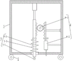
FIG. 1 is a schematic view of the overall structure of a flatness measuring apparatus for use in construction of constructional engineering according to the present invention;
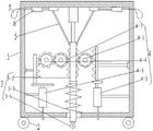
FIG. 2 is a cross-sectional view of a flatness measuring apparatus for construction of a construction work according to the present invention;
FIG. 3 is a cross-sectional view of a flatness measuring apparatus for construction of construction engineering according to the present invention;
FIG. 4 is a cross-sectional view of a flatness measuring apparatus for construction of a construction work according to the present invention;
fig. 5 is a plan view of a flatness measuring apparatus for construction of a construction work according to the present invention.
Description of the reference numerals:
1. the automatic measuring device comprises a machine shell, 2 parts of a first roller, 3 parts of a flatness measuring mechanism, 3-1 parts of a butting part, 3-2 parts of a vertical plate, 3-3 parts of a spring, 4 parts of a marking mechanism, 4-1 parts of a first gear, 4-2 parts of a first injector, 4-3 parts of a second gear, 4-4 parts of a third gear, 4-5 parts of a second injector, 5 parts of a supporting rod, 6 parts of a third injector, 7 parts of a balloon and 8 parts of a handle.
Detailed Description
The following detailed description of the present invention is provided in conjunction with the accompanying drawings, but it should be understood that the scope of the present invention is not limited to the specific embodiments. All other embodiments, which can be obtained by a person skilled in the art without any inventive step based on the embodiments of the present invention, are within the scope of the present invention.
Examples
As shown in fig. 1 to 5, the flatness measuring device for construction of a construction project provided by the present invention comprises: the bottom of the machine shell 1 is provided with an opening, and two sides of the opening are symmetrically provided with first rollers 2; the flatness measuring mechanism 3 comprises an abutting part 3-1, the top of the abutting part 3-1 is connected with a vertical plate 3-2 penetrating through an opening, the bottom of the abutting part 3-1 can be in contact with the ground, the top end of the vertical plate 3-2 is connected with the inner top wall of the machine shell 1 through a height adjusting assembly, a spring 3-3 is sleeved on the vertical plate 3-2, the top end of the spring 3-3 is connected with the vertical plate 3-2, and the bottom end of the spring 3-3 is connected with the bottom wall of the machine shell 1; the marking mechanism 4 comprises a first gear 4-1 which is rotatably connected with the front wall and the rear wall of the machine shell 1 through a first rotating shaft, the first gear 4-1 is respectively meshed with a first rack which is longitudinally arranged on a vertical plate 3-2 and a second rack which is longitudinally connected with the inner wall of the machine shell 1 in a sliding manner, the second rack is connected with a first injector 4-2 filled with lime water, the first injector 4-2 is fixedly connected with the inner wall of the machine shell 1 through a first connecting rod, and an outlet of the first injector 4-2 is communicated with a first through hole formed in the bottom wall of the machine shell 1. Wherein the height adjusting component is a telescopic rod with adjustable length.
In order to solve the problems that the flatness measuring device for building engineering construction in the prior art cannot mark the ground or the wall surface with the flatness which is detected to be not up to the standard when measuring the flatness and needs to correct the flatness, the flatness measuring device for building engineering construction needs to measure and supplement the ground or the wall surface at the same time.
When in use, a constructor can hold the flatness measuring device for the construction of the building engineering and place the device on the ground or the wall surface to be detected, at the moment, the two first rollers 2 at the bottom of the casing 1 contact the ground or the wall surface, when no bulge appears on the ground or the wall surface, the abutting part 3-1 below the opening also contacts the ground or the wall surface like the two first rollers 2, the spring 3-3 is in an original state and does not deform, at the moment, no mark is needed, when the bulge appears on the ground or the wall surface, the abutting part 3-1 moves to the bulge, under the action of the bulge, the abutting part 3-1 moves upwards, the vertical plate 3-2 fixedly connected with the abutting part 3-1 also moves upwards from the opening along the longitudinal direction, at the moment, the spring 3-3 is compressed, the length of the height adjusting component (telescopic rod) is shortened, when the vertical plate 3-2 moves upwards, the first rack longitudinally fixed on the vertical plate 3-2 also moves upwards, and the first rack is meshed with the first gear, so that the first gear 4-1 positioned on the left side of the vertical plate 3-2 is driven to rotate clockwise, or the first rack also moves upwards to drive the first gear 4-1 positioned on the right side of the vertical plate 3-2 to rotate anticlockwise, the first gear 4-1 is meshed with the second rack, and the second rack is connected with the inner wall of the casing 1 along the longitudinal sliding mode through the connecting piece, so that the second rack moves downwards, so that the injection handle of the first injector 4-2 is pushed, lime water of the first injector 4-2 is sprayed out, and the bulge of the first injector is marked. The working efficiency is improved.
Example 2
In embodiment 2, based on embodiment 1, in order to improve the application range of the device, the device can detect and mark the protrusion of the ground or the wall and the recess of the ground or the wall, so a vertical plate 3-2 is further provided with a third rack symmetrical to the first rack, the third rack is engaged with a second gear 4-3, the second gear 4-3 is connected to a second rotating shaft in a key manner, the second rotating shaft is rotatably connected to the front and rear side walls of the housing 1, the second gear 4-3 is engaged with a third gear 4-4, the third gear 4-4 is connected to a third rotating shaft in a key manner, the third rotating shaft is rotatably connected to the front and rear side walls of the housing 1, the second rotating shaft and the third rotating shaft are at the same height and parallel, the third gear 4-4 is engaged with a fourth rack longitudinally sliding along the inner wall of the housing 1, the fourth rack is connected to a second injector 4-5 containing lime water, the second injector 4-5 is fixedly connected to the inner wall of the housing 1 through a second connecting rod, and an outlet of the second injector 4-5 is communicated with a second through hole formed in the bottom wall of the housing 1.
The working principle is as follows: when a depression appears on the ground or the wall surface and the depression needs to be marked, the device needs to be placed on the ground or the wall surface, then the abutting part 3-1 is located in the depression, at the moment, the spring is stretched by 3-3 times, the vertical plate 3-2 penetrates out of the opening and moves downwards, the height adjusting component extends, at the moment, the first rack located on one side of the vertical plate 3-2 and the third rack located on the other side of the vertical plate 3-2 and symmetrical to the first rack both move downwards, so that the first gear 4-1 meshed with the first rack rotates anticlockwise, the second gear 4-3 meshed with the third rack rotates clockwise, the second gear 4-3 is meshed with the third gear 4-4 which is located at the same height in parallel with the second gear, so that the third gear 4-4 rotates anticlockwise, further, the fourth rack meshed with the third gear 4-4 slides downwards, the injection handle of the second injector 4-5 is pushed to move downwards, the injection handle of the lime water is sprayed to be marked, the mark provided by the mark of the depression and the mark can be marked at the same time, the convex degree and the mark can be measured by using a simple mark mechanism which does not accord with the measurement of the measurement structure of the flatness side, and the measurement of the flatness.
In order to facilitate more visual observation of the measurement result of the flatness, the top of the vertical plate 3-2 is symmetrically provided with support rods 5, the two support rods 5 are inverted splayed, the high end of each support rod 5 is hinged with a slide block, each slide block is connected with the inner top wall of the casing 1 in a sliding manner along the horizontal direction, the low end of each support rod 5 is hinged at the top end of the vertical plate 3-2, each slide block is fixedly connected with an injection handle of a third injector 6 fixed on the inner top wall of the casing 1 along the horizontal direction, each third injector 6 is filled with gas, and the gas outlet of each third injector 6 is hermetically connected with a balloon 7 filled with a small amount of gas.
The working principle is as follows: when no projection or recess exists on the ground or the wall surface and the flatness meets the requirement, the balloons 7 on the left side and the right side of the casing 1 are kept in an original state of being filled with a small amount of gas, when the projection appears on the ground or the wall surface, the abutting parts 3-1 and the vertical plates 3-2 move upwards at the moment, so that the height adjusting components are shortened, the supporting rods 5 hinged on the vertical plates 3-2 and the sliding blocks drive the sliding blocks to move in the direction away from the vertical plates 3-2, the third injectors 6 are pushed, the gas in the third injectors 6 is filled into the balloons 7, the balloons 7 are further expanded, when the recess appears on the ground or the wall surface, the abutting parts 3-1 and the vertical plates 3-2 move downwards at the moment, the height adjusting components are extended, the supporting rods 5 hinged on the vertical plates 3-2 and the sliding blocks are driven to move in the direction close to the vertical plates 3-2, injection handles of the third injectors 6 are pulled, the gas in the balloons 7 is sucked into the third injectors 6 again, and the balloons 7 are reduced. The measurement result of the concavity or convexity of the ground or wall surface is visually given by the change of the size of the balloon 7.
The specific structure of the abutting part 3-2 is given, and the specific size is given for enabling the abutting part 3-2 to meet the measurement requirement, the abutting part 3-1 is a second roller, and the diameter of the second roller is 5-20mm
Furthermore, a specific structure of the height adjusting assembly is provided, wherein the height adjusting assembly comprises a first sleeve and a first sleeve rod, the first sleeve rod is sleeved outside the first sleeve rod and is connected with the top end of the vertical plate 3-2 in a sliding mode along the length direction of the first sleeve rod, and the first sleeve is connected with the inner top wall of the casing 1.
Furthermore, a sealing door is arranged on the front side wall of the casing 1, so that lime water can be conveniently and timely supplemented into the first injector 4-2 and the second injector 4-5, or maintenance is convenient.
Further, a handle 8 is arranged at the top of the casing 1. The handheld device is convenient to carry out flatness measurement and marking.
Furthermore, the side wall of the casing 1 is provided with handrails, so that the handrails can be held by hands conveniently, and the device is moved slowly by controlling the moving speed of the device, so that the flatness measurement and marking can be carried out.
Further, in order to be more portable and to reduce weight, the casing 1, the riser 3-2, the height adjusting assembly, the first gear 4-1, the first rotation shaft, the first rack, the second rack, and the first injector 4-2 are made of a resin material, which may be one of PP or PE.
Although embodiments of the present invention have been shown and described, it will be appreciated by those skilled in the art that changes, modifications, substitutions and alterations can be made in these embodiments without departing from the principles and spirit of the invention, the scope of which is defined in the appended claims and their equivalents.
Claims (9)
1. The utility model provides a roughness measuring device is used in building engineering construction which characterized in that includes:
the bottom of the shell (1) is provided with an opening, and two sides of the opening are symmetrically provided with first rollers (2);
the flatness measuring mechanism (3) comprises an abutting part (3-1), the top of the abutting part (3-1) is connected with a vertical plate (3-2) penetrating out of an opening, the bottom of the abutting part (3-1) can be in contact with the ground, the top end of the vertical plate (3-2) is connected with the inner top wall of the machine shell (1) through a height adjusting assembly, a spring (3-3) is sleeved on the vertical plate (3-2), the top end of the spring (3-3) is connected with the vertical plate (3-2), and the bottom end of the spring (3-3) is connected with the bottom wall of the machine shell (1);
the marking mechanism (4) comprises a first gear (4-1) which is rotatably connected with the front wall and the rear wall of the machine shell (1) through a first rotating shaft, the first gear (4-1) is respectively meshed with a first rack which is longitudinally arranged on a vertical plate (3-2) and a second rack which is longitudinally and slidably connected with the inner wall of the machine shell (1), the second rack is connected with a first injector (4-2) filled with lime water, the first injector (4-2) is fixedly connected with the inner wall of the machine shell (1) through a first connecting rod, and an outlet of the first injector (4-2) is communicated with a first through hole formed in the bottom wall of the machine shell (1).
2. The flatness measuring device for building engineering construction according to claim 1, wherein a third rack symmetrical to the first rack is further provided on the vertical plate (3-2), the third rack is engaged with a second gear (4-3), the second gear (4-3) is keyed onto a second rotating shaft, the second rotating shaft is rotatably connected to the front and rear side walls of the casing (1), the second gear (4-3) is engaged with a third gear (4-4), the third gear (4-4) is keyed onto a third rotating shaft, the third rotating shaft is rotatably connected to the front and rear side walls of the casing (1), the second rotating shaft and the third rotating shaft are at the same height and parallel, the third gear (4-4) is engaged with a fourth rack longitudinally sliding along the inner wall of the casing (1), the fourth rack is connected with a second injector (4-5) filled with lime water, the second injector (4-5) is fixedly connected to the inner wall of the casing (1) through a second connecting rod, and an outlet of the second injector (4-5) is provided in communication with the bottom wall of the casing (1).
3. The flatness measuring device for construction of building engineering according to claim 1 or 2, wherein the top of the vertical plate (3-2) is symmetrically provided with support rods (5), two support rods (5) are in an inverted splayed shape, the high end of each support rod (5) is hinged with a slide block, each slide block is connected with the inner top wall of the casing (1) in a sliding manner along the horizontal direction, the low end of each support rod (5) is hinged with the top end of the vertical plate (3-2), each slide block is respectively fixedly connected with the injection handle of a third injector (6) fixed on the inner top wall of the casing (1) along the horizontal direction, each third injector (6) is filled with gas, and the gas outlet of each third injector (6) is hermetically connected with a balloon (7) filled with a small amount of gas.
4. The flatness measuring device for construction of building engineering according to claim 1, wherein said abutment member (3-1) is a second roller, and the diameter of the second roller is 5-20mm.
5. The flatness measuring device for building engineering construction according to claim 1, wherein the height adjusting component comprises a first sleeve and a first sleeve rod, the first sleeve is sleeved outside the first sleeve rod, the first sleeve rod is connected in a sliding manner along the length direction of the first sleeve, the first sleeve rod is connected with the top end of the vertical plate (3-2), and the first sleeve is connected with the inner top wall of the casing (1).
6. The flatness measuring device for construction of building engineering according to claim 1, wherein a sealing door is provided on a front side wall of the casing (1).
7. The flatness measuring device for construction of building engineering according to claim 1, wherein a grip (8) is provided at the top of the casing (1).
8. The flatness measuring device for construction of building engineering according to claim 1, wherein handrails are provided on the side walls of the casing (1).
9. The flatness measuring device for construction of construction engineering according to claim 1, wherein the casing (1), the riser (3-2), the height adjusting assembly, the first gear (4-1), the first rotation shaft, the first rack, the second rack, and the first injector (4-2) are made of a resin material.
Priority Applications (1)
| Application Number | Priority Date | Filing Date | Title |
|---|---|---|---|
| CN202210865965.1A CN115265343A (en) | 2022-07-22 | 2022-07-22 | Flatness measuring device for building engineering construction |
Applications Claiming Priority (1)
| Application Number | Priority Date | Filing Date | Title |
|---|---|---|---|
| CN202210865965.1A CN115265343A (en) | 2022-07-22 | 2022-07-22 | Flatness measuring device for building engineering construction |
Publications (1)
| Publication Number | Publication Date |
|---|---|
| CN115265343A true CN115265343A (en) | 2022-11-01 |
Family
ID=83767275
Family Applications (1)
| Application Number | Title | Priority Date | Filing Date |
|---|---|---|---|
| CN202210865965.1A Withdrawn CN115265343A (en) | 2022-07-22 | 2022-07-22 | Flatness measuring device for building engineering construction |
Country Status (1)
| Country | Link |
|---|---|
| CN (1) | CN115265343A (en) |
Cited By (1)
| Publication number | Priority date | Publication date | Assignee | Title |
|---|---|---|---|---|
| CN117781829A (en) * | 2024-02-23 | 2024-03-29 | 云南建研建设工程检测鉴定有限公司 | Building engineering quality flatness detection device |
-
2022
- 2022-07-22 CN CN202210865965.1A patent/CN115265343A/en not_active Withdrawn
Cited By (2)
| Publication number | Priority date | Publication date | Assignee | Title |
|---|---|---|---|---|
| CN117781829A (en) * | 2024-02-23 | 2024-03-29 | 云南建研建设工程检测鉴定有限公司 | Building engineering quality flatness detection device |
| CN117781829B (en) * | 2024-02-23 | 2024-04-30 | 云南建研建设工程检测鉴定有限公司 | Building engineering quality flatness detection device |
Similar Documents
| Publication | Publication Date | Title |
|---|---|---|
| CN113404325B (en) | Single-opening intelligent grouting joint filling machine for wall cracks and construction method | |
| CN108729631B (en) | Vertical automatic wall tile sticking device for building construction | |
| CN107300351A (en) | One kind building monitoring plank rapid size detection device | |
| CN111829420A (en) | Device for automatically detecting wall surface flatness | |
| CN115265343A (en) | Flatness measuring device for building engineering construction | |
| CN107322391A (en) | A kind of building wall automatically grinding equipment | |
| CN109211187A (en) | A kind of plotting board and mapping method | |
| CN112097598B (en) | Soil layer thickness detector rolls that water conservancy construction was used | |
| CN114216399A (en) | Building quality detection device and method | |
| CN210533270U (en) | Wall that engineering was managed and was used levels measuring device | |
| CN111412817A (en) | Simple and easy type concrete thickness detection instrument for building engineering | |
| CN218864979U (en) | Building energy conservation engineering quality flatness detection device | |
| CN216361586U (en) | Building material's for building engineering roughness check out test set | |
| CN211346677U (en) | Be used for engineering flatness measuring apparatu | |
| CN210689477U (en) | Road bridge degree of depth measuring device | |
| CN211042074U (en) | Detection device for detecting marble flatness | |
| CN211668972U (en) | Building material intensity detection device convenient to remove | |
| CN214040673U (en) | Crack detection equipment for building engineering construction | |
| CN210923415U (en) | Building engineering quality detection device | |
| CN213902222U (en) | Fitment roughness measuring device | |
| CN208914083U (en) | A kind of idler wheel lineation device | |
| CN205898107U (en) | Hemisphere apolegamy device | |
| CN207103183U (en) | The device of Belt Length is surveyed using robot single shaft arm | |
| CN220623443U (en) | Tunnel construction measuring device | |
| CN214037641U (en) | Supporting structure for installation of chemical equipment |
Legal Events
| Date | Code | Title | Description |
|---|---|---|---|
| PB01 | Publication | ||
| PB01 | Publication | ||
| SE01 | Entry into force of request for substantive examination | ||
| SE01 | Entry into force of request for substantive examination | ||
| WW01 | Invention patent application withdrawn after publication | ||
| WW01 | Invention patent application withdrawn after publication |
Application publication date: 20221101 |