CN115265319B - Detection tool and detection method for height of bevel gear clamp spring groove - Google Patents
Detection tool and detection method for height of bevel gear clamp spring groove Download PDFInfo
- Publication number
- CN115265319B CN115265319B CN202211186290.4A CN202211186290A CN115265319B CN 115265319 B CN115265319 B CN 115265319B CN 202211186290 A CN202211186290 A CN 202211186290A CN 115265319 B CN115265319 B CN 115265319B
- Authority
- CN
- China
- Prior art keywords
- measuring
- gauge
- positioning
- bevel gear
- face
- Prior art date
- Legal status (The legal status is an assumption and is not a legal conclusion. Google has not performed a legal analysis and makes no representation as to the accuracy of the status listed.)
- Active
Links
Images


Classifications
-
- G—PHYSICS
- G01—MEASURING; TESTING
- G01B—MEASURING LENGTH, THICKNESS OR SIMILAR LINEAR DIMENSIONS; MEASURING ANGLES; MEASURING AREAS; MEASURING IRREGULARITIES OF SURFACES OR CONTOURS
- G01B5/00—Measuring arrangements characterised by the use of mechanical techniques
- G01B5/02—Measuring arrangements characterised by the use of mechanical techniques for measuring length, width or thickness
Abstract
The invention relates to the technical field of detection tools, in particular to a detection tool and a detection method for the height of a bevel gear circlip groove, wherein the detection tool comprises a middle detection body, a first detection body and a second detection body, the middle detection body is arranged on the reference end surface of a bevel gear, and a reference surface is arranged on the middle detection body; the first sample is arranged on the reference surface of the middle sample, and a through end measuring end surface is arranged on the first sample and used for approaching the surface to be detected so as to detect whether the distance to be detected between the reference end surface and the surface to be detected is larger than the minimum limit size; the second specimen is arranged on a reference surface of the middle specimen, the second specimen is provided with a stop end measuring end surface, and the stop end measuring end surface is used for approaching the surface to be detected to detect whether the distance to be detected between the reference end surface and the surface to be detected is smaller than the maximum limit size.
Description
Technical Field
The invention relates to the technical field of detection tools, in particular to a detection tool and a detection method for the height of a bevel gear clamp spring groove.
Background
Gears are common mechanical parts, and most of the mechanical parts which move by rotation are installed in a positioning way by inner holes. A clamping spring groove is usually arranged in an inner hole of a gear matched with some precision machinery, and the clamping spring groove is matched with a clamping spring matched with a shaft to perform axial limiting. For example, a side gear bore in an automotive differential has a snap spring groove, and the snap spring groove in the bore is dimensionally restricted from the outer end face of the gear (the outer end face of the gear is a mounting face and is a locating face and is a reference for axial dimensions). As shown in fig. 1, since the height L ± δ of the jump ring groove (the distance between the outer end surface and the bottom surface of the jump ring groove) is an indirect dimension, a commercially available length measuring instrument cannot be directly used for detection.
A contour gauge and a three-dimensional coordinate measuring instrument in modern detection equipment can be used for precision measurement, but cannot be used for direct measurement, the distances from a clamp spring groove and an outer end face to a workpiece shaft end face need to be measured respectively, then the difference is calculated for the two distances, the distance from the bottom face of the clamp spring groove to the outer end face is indirectly converted, and errors are prone to occurring. In addition, the precision instrument has high requirement on the inspection condition and low detection efficiency, is only suitable for verification and inspection in a precision measurement room and cannot be used for inspection on a production site. For example, the patent with the application number of CN201910616105.2 discloses a detection tool and a detection method for measuring the groove width of an inner hole ring and the distance between the inner hole ring and a relative outer shoulder, and the measurement is also carried out by means of a dial indicator, a gauge block and the like.
Disclosure of Invention
In order to solve the problem that the quality deviation of a product cannot be found in time by means of a measuring device in the prior art, the invention provides a convenient and fast checking fixture and a convenient and fast detecting method for the height of a bevel gear clamp spring groove, which can be used in a workshop.
The technical scheme adopted by the invention for solving the technical problems is as follows:
the utility model provides an examine utensil of bevel gear jump ring groove height, wherein, bevel gear has the reference terminal surface and waits to detect the face with the reference terminal surface is parallel, examines whether the distance that awaits measuring that is used for detecting between reference terminal surface and the face of waiting to detect accords with the requirement, examine the utensil and include:
the bottom end face of the middle sample is arranged on the reference end face of the bevel gear, and a reference face is arranged on the middle sample;
the first sample is arranged on a reference surface of the middle sample, and is provided with a through end measuring end surface which is used for approaching the surface to be detected so as to detect whether the distance to be detected between the reference end surface and the surface to be detected is larger than the minimum limit size;
the second sample is arranged on the reference surface of the middle sample, and a stop end measuring end surface is arranged on the second sample and used for approaching the surface to be detected so as to detect whether the distance to be detected between the reference end surface and the surface to be detected is smaller than the maximum limit size.
Furthermore, the surface to be detected is the groove bottom surface of a clamp spring groove on the peripheral surface of the bevel gear, one side of the through end measuring end surface of the first sample body is provided with a first measuring lug, one side of the dead end measuring end surface of the second sample body is provided with a second measuring lug, the thicknesses of the first measuring lug and the second measuring lug are both smaller than the size of the clamp spring groove, and the first measuring lug or the second measuring lug can extend into the clamp spring groove by a rotation set angle so as to detect the distance to be detected between the groove bottom surface and the reference end surface.
Furthermore, the benchmark terminal surface be located the outside of bevel gear, the jump ring groove is located the inboard of bevel gear, middle sample on be equipped with the through-hole that supplies logical gauge pole or no-go gauge pole to stretch into, the through-hole include eccentric orfice and the slotted hole that supplies first measurement lug and second measurement lug to pass through, the eccentric orfice is for being greater than semicircle hole, first measurement lug or second measurement lug can stretch into in the jump ring groove after rotating the settlement angle around the central line of eccentric orfice in order to detect the distance to be measured between groove bottom surface and the benchmark terminal surface. The eccentric orfice is greater than the semicircle orifice, can not deviate from the eccentric orfice when first measuring staff or second measuring staff are rotatory like this to realize first measuring staff or second measuring staff and rotate around the central line of eccentric orfice, the operation of being convenient for.
Further, the reference end face is located between the reference surface and the surface to be detected, the first sample body is provided with a through end reference surface matched with the reference surface of the middle sample body, the distance between the through end reference surface and the through end measuring end face is a designed through end size HT, and the calculation formula of the designed through end size HT is as follows:
HT=L-δ+H, (1)
wherein H is the distance L between the reference surface and the bottom end surface of the middle sample, which is the basic design size of the distance to be measured, and delta is the design tolerance of the distance to be measured;
the second sample is provided with a stop end reference surface matched with the reference surface of the middle sample, the distance between the stop end reference surface and the stop end measuring end surface is a designed stop end size HZ, and the calculation formula of the designed stop end size HZ is as follows:
HZ=L+δ+H (2)
wherein H is the distance between the reference surface and the bottom end surface of the intermediate sample, L is the basic design dimension of the distance to be measured, and delta is the design tolerance of the distance to be measured.
Furthermore, the middle sample comprises a positioning shaft sleeve, the bottom end face of the positioning shaft sleeve is arranged on the reference end face, and the center line of the positioning shaft sleeve is superposed with the center line of the bevel gear.
Furthermore, the first sample body comprises a through gauge rod, the through gauge rod comprises a first positioning table and a first gauge rod, the first positioning table is used for being installed on the positioning shaft sleeve, the first gauge rod extends into an inner hole of the bevel gear, the through end reference surface is arranged on the first positioning table, and the through end measuring end surface is arranged at the through end, far away from the first positioning table, of the first gauge rod; the second sample comprises a no-go gauge rod, the no-go gauge rod comprises a second positioning table and a second gauge rod, the second positioning table is used for being installed on the positioning shaft sleeve, the second gauge rod is used for extending into an inner hole of the bevel gear, a no-go end datum plane is arranged on the second positioning table, and a no-go end measuring end face is arranged at a no-go end of the second gauge rod, which is far away from the second positioning table.
The gauge further comprises a positioning mechanism, and the positioning mechanism comprises a first positioning mechanism for circumferential pre-positioning after the gauge rod or the no-gauge rod is arranged in the positioning shaft sleeve, and a second positioning mechanism for circumferential measurement and positioning after the gauge rod or the no-gauge rod rotates for a set angle around the central line of the eccentric hole.
Furthermore, first positioning mechanism and second positioning mechanism all include the locating pin, general gage measuring staff and no-go gage measuring staff on be equipped with the pinhole that matches with the locating pin, be equipped with the locating hole that matches with the locating pin on the location axle sleeve.
A detection method for the checking fixture for the height of the bevel gear clamp spring groove comprises the following steps of measuring a go gauge and a no-go gauge:
the general gauge measurement comprises the following steps:
s11: firstly, mounting a positioning shaft sleeve to ensure that the bottom end surface of the positioning shaft sleeve is attached to the reference end surface of the bevel gear;
s12: the through gauge rod is plugged into the inner hole of the bevel gear from the through hole of the positioning shaft sleeve,
s13: the gauge rod drives the first measuring lug thereon to rotate around the central line of the eccentric hole by a set angle, and then the circumferential positioning between the gauge rod and the positioning shaft sleeve is carried out through the positioning pin;
s14, observing whether the through end reference surface of the through gauge measuring rod abuts against the reference surface of the positioning shaft sleeve or not, wherein if the through end reference surface abuts against the reference surface of the positioning shaft sleeve, the through end measuring end surface of the through gauge measuring rod is not contacted with the plane to be measured, the through gauge is qualified in measurement, and otherwise, the through gauge is unqualified in measurement;
the no-go measurement comprises the following steps:
s21: firstly, mounting a positioning shaft sleeve to ensure that the bottom end surface of the shaft sleeve is attached to the reference end surface of the bevel gear;
s22: the non-stop gauge rod is plugged into the inner hole of the bevel gear from the through hole of the positioning shaft sleeve,
s23: the non-return gauge measuring rod drives the second measuring lug to rotate around the center line of the eccentric hole by a set angle, the non-return end measuring end face of the non-return gauge measuring rod is made to be in contact with the plane to be measured, and then the non-return gauge measuring rod and the positioning shaft sleeve are circumferentially positioned through the positioning pin;
and S24, observing whether the stop end reference surface of the stop gauge measuring rod abuts against the reference surface of the positioning shaft sleeve or not, wherein if the stop end reference surface does not abut against the reference surface of the positioning shaft sleeve, the stop gauge is qualified in measurement, and otherwise, the stop gauge is unqualified in measurement.
Preferably, after the through gauge rod or the no-gauge rod is plugged into the inner hole of the bevel gear from the through hole of the positioning shaft sleeve, circumferential pre-positioning between the through gauge rod or the no-gauge rod and the positioning shaft sleeve is firstly carried out, and then the through gauge rod or the no-gauge rod rotates around the center line of the eccentric hole for a set angle.
Has the advantages that:
(1) The device adopts a mechanical measurement structure, and the middle sample, the first sample and the second sample are matched, so that whether the distance between a certain surface to be detected and a reference end surface meets the requirement or not can be measured;
(2) The method has the advantages that the height of the clamp spring groove to be measured in the hole (the distance between the bottom surface of the groove and the reference end surface) is converted into an external measurement structure through the positioning shaft sleeve, so that the problem that the indirect measurement of the height of the clamp spring groove in the inner hole of the bevel gear is inaccurate is solved;
(3) According to the gauge, the second measuring lug is arranged on the go gauge rod, the second measuring lug is arranged on the no-go gauge rod and is matched with the eccentric hole and the slotted hole in the positioning shaft sleeve, and the go gauge rod or the no-go gauge rod rotates around the central line of the eccentric hole, so that the first measuring lug or the second measuring lug can extend into the clamp spring slot, the distance between the slot bottom surface and the reference end surface is detected, and the problem that the conventional gauge is difficult to extend into the clamp spring slot for measurement is solved;
(4) This application leads to the eccentric orfice and is greater than the semicircle orifice, can not deviate from the eccentric orfice when first measuring staff or second measuring staff are rotatory like this to realize that first measuring staff or second measuring staff rotate around the central line of eccentric orfice, further improve the convenience of operation.
(5) The size of the lead gauge measuring rod and the no-go gauge measuring rod is correlated with the distance to be measured, and the actual reading is not needed when testing, and only the position relation between the lead end datum plane or the no-go end datum plane and the reference plane needs to be observed, the quantitative index is converted into the sensory index, the operation and the realization are easy for workers, and the deviation caused by reading habits of different people is solved simultaneously.
Drawings
In order to more clearly illustrate the technical solutions of the embodiments of the present invention, the drawings needed to be used in the description of the embodiments are briefly introduced below, and it is obvious that the drawings in the following description are only some embodiments of the present invention, and it is obvious for those skilled in the art to obtain other drawings based on the drawings without creative efforts.
FIG. 1 is a structural section view of a tested bevel gear;
FIG. 2 is an elevation view of the fit relationship of the gauge rod, the locating boss and the bevel gear;
FIG. 3 is a top view of the fit relationship of the gauge rod, the locating bushing and the bevel gear;
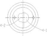
FIG. 4 is an elevation view of the mating relationship of the non-stop gauge stem, the locating bushing and the bevel gear;
FIG. 5 is a top view of the mating relationship of the non-stop gauge stem, the locating bushing and the bevel gear;
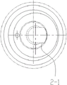
FIG. 6 is a front view of the gauge stem;
FIG. 7 is a bottom view of the gauge stem;
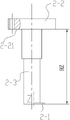
FIG. 8 is a front view of the non-stop gauge stem;
FIG. 9 is a bottom view of the non-stop gauge bar;
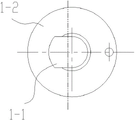
FIG. 10 is a cross-sectional view of the locating boss;
fig. 11 is a top view of the locating boss.
The device comprises a reference surface, a reference end, a bevel gear, 5-1, a reference end surface, 5-2, a clamp spring groove, 5-21, a groove bottom surface, HT, a design through end size, HZ, a design end stop size, H, a distance between the reference surface and a bottom end surface of an intermediate sample, L, a basic design size of a distance to be measured, delta, and a design tolerance of the distance to be measured.
Detailed Description
The technical solutions in the embodiments of the present invention will be clearly and completely described below with reference to the drawings in the embodiments of the present invention, and it is obvious that the described embodiments are only a part of the embodiments of the present invention, and not all of the embodiments. The following description of at least one exemplary embodiment is merely illustrative in nature and is in no way intended to limit the invention, its application, or uses. All other embodiments, which can be derived by a person skilled in the art from the embodiments given herein without making any creative effort, shall fall within the protection scope of the present invention.
It is noted that the terminology used herein is for the purpose of describing particular embodiments only and is not intended to be limiting of example embodiments according to the present application. As used herein, the singular forms "a", "an" and "the" are intended to include the plural forms as well, and it should be understood that when the terms "comprises" and/or "comprising" are used in this specification, they specify the presence of stated features, steps, operations, devices, components, and/or combinations thereof, unless the context clearly indicates otherwise.
The relative arrangement of the components and steps, the numerical expressions and numerical values set forth in these embodiments do not limit the scope of the present invention unless specifically stated otherwise. Meanwhile, it should be understood that the sizes of the respective portions shown in the drawings are not drawn in an actual proportional relationship for the convenience of description. Techniques, methods, and apparatus known to those of ordinary skill in the relevant art may not be discussed in detail but are intended to be part of the specification where appropriate. In all examples shown and discussed herein, any particular value should be construed as merely illustrative, and not limiting. Thus, other examples of the exemplary embodiments may have different values. It should be noted that: like reference numbers and letters refer to like items in the following figures, and thus, once an item is defined in one figure, it need not be discussed further in subsequent figures.
In the description of the present invention, it is to be understood that the directions or positional relationships indicated by the directional terms such as "front, rear, upper, lower, left, right", "lateral, vertical, horizontal" and "top, bottom", etc., are generally based on the directions or positional relationships shown in the drawings, and are for convenience of description and simplicity of description only, and in the case of not making a reverse description, these directional terms do not indicate and imply that the device or element referred to must have a particular orientation or be constructed and operated in a particular orientation, and therefore, should not be considered as limiting the scope of the present invention; the terms "inner and outer" refer to the inner and outer relative to the profile of the respective component itself.
For ease of description, spatially relative terms such as "above … …", "above … …", "above … … upper surface", "above", etc. may be used herein to describe the spatial positional relationship of one device or feature to other devices or features as shown in the figures. It will be understood that the spatially relative terms are intended to encompass different orientations of the device in use or operation in addition to the orientation depicted in the figures. For example, if a device in the figures is turned over, devices described as "above" or "on" other devices or configurations would then be oriented "below" or "under" the other devices or configurations. Thus, the exemplary term "above … …" may include both orientations of "above … …" and "below … …". The device may be otherwise variously oriented (rotated 90 degrees or at other orientations) and the spatially relative descriptors used herein interpreted accordingly.
It should be noted that the terms "first", "second", and the like are used to define the components, and are only used for convenience of distinguishing the corresponding components, and the terms have no special meanings unless otherwise stated, and therefore, the scope of the present invention should not be construed as being limited.
As shown in fig. 1, an object to be measured is a bevel gear 5, the bevel gear comprises a gear part and a gear shaft part, the bevel gear 5 is provided with a reference end surface 5-1 and a surface to be detected, and the surface to be detected is required to be parallel to the reference end surface 5-1, the invention provides a checking fixture for the height of a circlip groove of the bevel gear, as shown in fig. 2 to 11, the checking fixture is used for detecting whether a distance to be detected between the reference end surface 5-1 and the surface to be detected meets the requirement or not, the checking fixture comprises a middle checking body, a first checking body and a second checking body, the middle checking body is arranged on the reference end surface 5-1 of the bevel gear 5, and a reference surface 4-4 is arranged on the middle checking body; the first sample is arranged on a reference surface 4-4 of the middle sample, and a through end measuring end surface is arranged on the first sample and is used for approaching the surface to be detected so as to detect whether the distance to be detected between the reference end surface 5-1 and the surface to be detected is larger than the minimum limit size or not; the second sample is arranged on the reference surface 4-4 of the middle sample, and the second sample is provided with a stop end measuring end surface which is used for approaching the surface to be detected so as to detect whether the distance to be detected between the reference end surface 5-1 and the surface to be detected is smaller than the maximum limit size.
The surface to be detected is a groove bottom surface 5-21 of a clamp spring groove 5-2 on the peripheral surface of the bevel gear 5, a first measuring lug 1-1 is arranged on one side of a through end measuring end surface of the first detecting body, a second measuring lug 2-1 is arranged on one side of a stop end measuring end surface of the second detecting body, the thicknesses of the first measuring lug 1-1 and the second measuring lug 2-1 are both smaller than the size of the clamp spring groove 5-2, and the first measuring lug 1-1 or the second measuring lug 2-1 can extend into the clamp spring groove 5-2 by rotating a set angle so as to detect the distance to be detected between the groove bottom surface 5-21 and a reference end surface 5-1.
As an embodiment of the invention, the reference end face 5-1 and the surface to be detected can be both positioned on the inner side of the bevel gear 5, or can be both positioned on the outer side of the bevel gear 5, or one of the reference end face 5-1 and the surface to be detected is positioned on the inner side of the bevel gear 5, or the other one is positioned on the inner side and the outer side of the bevel gear 5, a through hole into which the go-no-go gauge rod 1 or the no-go gauge rod 2 extends is arranged on the middle sample body, the through hole comprises an eccentric hole 4-1 and a slotted hole 4-2 through which the first measuring lug 1-1 and the second measuring lug 2-1 pass, and the first measuring lug 1-1 or the second measuring lug 2-1 can extend into the clamp spring slot 5-2 after rotating for a set angle around the central line of the eccentric hole 4-1 to detect the distance between the slot bottom face 5-21 and the reference end face 5-1. The eccentric hole 4-1 is communicated with the slotted hole 4-2, in the invention, the size is slightly larger than the first measuring rod 1-3 or the second measuring rod 2-3 (the first measuring rod 1-3 and the second measuring rod 2-3 can be designed into the same diameter), the slotted hole 4-2 is matched with the shape of the first measuring lug 1-1 or the second measuring lug 1-2 (the first measuring lug 1-1 and the second measuring lug 1-2 can be designed into the same size), and certainly can be larger than the size of the first measuring lug 1-1 or the second measuring lug 1-2, in addition, the eccentric hole 4-1 is larger than the semicircular hole, so that the first measuring rod 1-3 or the second measuring rod 2-3 can not be separated from the eccentric hole 4-1 when rotating, thereby realizing that the first measuring rod 1-3 or the second measuring rod 2-3 rotates around the central line of the eccentric hole 4-1, and facilitating the operation.
In the invention, the end face of the positioning shaft sleeve 4 far away from the reference end face of the bevel gear is a reference face 4-4, the reference end face 5-1 is positioned between the reference face 4-4 and a surface to be detected, the first sample body is provided with a through end reference face 1-21 matched with the reference face 4-4 of the middle sample body, the distance between the through end reference face 1-21 and the through end measuring end face is a designed through end size HT, and the calculation formula of the designed through end size HT is as follows:
HT=L-δ+H, (1)
wherein H is the distance between the reference surface 4-4 and the bottom end surface of the middle sample, L is the basic design size of the distance to be measured, and delta is the design tolerance of the distance to be measured;
the second sample is provided with a stop end reference surface 2-21 matched with the reference surface 4-4 of the middle sample, the distance between the stop end reference surface 2-21 and the stop end measuring end surface is a designed stop end size HZ, and the calculation formula of the designed stop end size HZ is as follows:
HZ=L+δ+H (2)
wherein H is the distance between the reference surface 4-4 and the bottom end surface of the intermediate sample, L is the basic design size of the distance to be measured, and delta is the design tolerance of the distance to be measured.
The distance H between the reference surface 4-4 and the reference end surface 5-1, the basic design dimension L of the distance to be measured and the design tolerance delta of the distance to be measured are all design values.
The middle sample comprises a positioning shaft sleeve 4, the bottom end face of the positioning shaft sleeve 4 is arranged on a reference end face 5-1, a reference surface 4-4 of the middle sample is positioned at the top, and the center line of the positioning shaft sleeve 4 is superposed with the center line of the bevel gear 5, and the specific realization mode is as follows: the positioning shaft sleeve 4 is provided with a matching hole matched with the peripheral surface of a gear shaft of the bevel gear 5, and the positioning shaft sleeve 4 is sleeved outside the gear shaft.
The first sample body comprises a through gauge measuring rod 1, the through gauge measuring rod 1 comprises a first positioning table 1-2 used for being installed on a positioning shaft sleeve 4 and a first measuring rod 1-3 used for extending into an inner hole of a bevel gear 5, a through end reference surface 1-21 is arranged on the first positioning table 1-2, and a through end measuring end surface is arranged at a through end T of the first measuring rod 1-3 far away from the first positioning table.
The second test body comprises a no-go gauge rod 2, the no-go gauge rod 2 comprises a second positioning table 2-2 installed on the positioning shaft sleeve 4 and a second gauge rod 2-3 extending into an inner hole of the bevel gear 5, a no-go end reference surface 2-21 is arranged on the second positioning table 2-2, and a no-go end measuring end surface is arranged at a no-go end Z of the second gauge rod 2-3 far away from the second positioning table.
The gauge also comprises a positioning mechanism, and the positioning mechanism comprises a first positioning mechanism and a second positioning mechanism, wherein the first positioning mechanism is used for carrying out circumferential pre-positioning after the gauge rod 1 or the gauge rod 2 is arranged in the positioning shaft sleeve 4, and the second positioning mechanism is used for carrying out circumferential measurement and positioning after the gauge rod 1 or the gauge rod 2 rotates around the center line of the eccentric hole 4-1 by a set angle.
The first positioning mechanism and the second positioning mechanism both comprise positioning pins 3, pin holes matched with the positioning pins 3 are formed in the go gauge rod 1 and the no-go gauge rod 2, and positioning holes 4-3 matched with the positioning pins 3 are formed in the positioning shaft sleeve 4. The number of the positioning holes 4-3 on the positioning shaft sleeve 4 is two, one is used for circumferential pre-positioning of the go gauge rod 1 or the no-go gauge rod 2, the other is used for circumferential measurement positioning after the go gauge rod 1 or the no-go gauge rod 2 rotates by a set angle, and when the circumferential pre-positioning or the circumferential measurement positioning is needed, the positioning pin 3 penetrates through a pin hole of the go gauge rod 1 or the no-go gauge rod 2 and then is inserted into the corresponding positioning hole 4-3.
A detection method for the bevel gear jump ring groove height detection tool comprises the following steps of go gauge measurement and no-go gauge measurement:
the general gauge measurement comprises the following steps:
s11: firstly, mounting a positioning shaft sleeve 4 to ensure that the bottom end surface of the positioning shaft sleeve 4 is attached to a reference end surface 5-1 of a bevel gear 5;
s12: the through gauge rod 1 is plugged into an inner hole of the bevel gear 5 from a through hole of the positioning shaft sleeve 4,
s13: the gauge rod 1 drives a first measuring lug 1-1 on the gauge rod to rotate around the center line of the eccentric hole 4-1 by a set angle, and then circumferential measuring and positioning between the gauge rod 1 and the positioning shaft sleeve 4 are carried out through the positioning pin 3;
s14, observing whether the through end reference surfaces 1-21 of the through gauge measuring rod 1 abut against the reference surfaces 4-4 of the positioning shaft sleeve 4 or not, wherein if the through end reference surfaces 1-21 abut against the reference surfaces 4-4 of the positioning shaft sleeve 4, the through gauge measuring end surface of the through gauge measuring rod 1 is not contacted with the plane to be measured, the through gauge is qualified in measurement, otherwise, the through gauge is unqualified in measurement;
the no-go measurement comprises the following steps:
s21: firstly, installing a positioning shaft sleeve 4 to ensure that the bottom end surface of the shaft sleeve is attached to a reference end surface 5-1 of a bevel gear 5;
s22: the non-stop gauge rod 2 is inserted into the inner hole of the bevel gear 5 from the through hole of the positioning shaft sleeve 4,
s23: the no-go gauge rod 2 drives a second measuring lug 2-1 on the no-go gauge rod to rotate around the central line of the eccentric hole 4-1 by a set angle, the end-stop measuring end face of the no-go gauge rod 2 is made to contact with a plane to be measured, and then circumferential measuring and positioning between the no-go gauge rod 2 and the positioning shaft sleeve 4 are carried out through the positioning pin 3;
s24, observing whether the no-go end reference surface 2-21 of the no-go gauge rod 2 abuts against the reference surface 4-4 of the positioning shaft sleeve 4 or not, if the no-go end reference surface 2-21 does not abut against the reference surface 4-4 of the positioning shaft sleeve 4, namely a uniform gap (capable of transmitting light) is formed between the no-go end reference surface 2-21 and the reference surface 4-4 of the positioning shaft sleeve 4, the no-go gauge is qualified in measurement, and otherwise the no-go gauge is unqualified in measurement.
In the invention, only if both the go gauge measurement and the no-go gauge measurement meet the requirements, the distance to be measured from the reference end face 5-1 to the groove bottom face 5-21 is qualified, otherwise, one or both of the go gauge measurement and the no-go gauge measurement do not meet the requirements, and the distance to be measured is unqualified.
After the through gauge rod 1 or the no-gauge rod 2 is plugged into an inner hole of the bevel gear 5 from a through hole of the positioning shaft sleeve 4, circumferential pre-positioning between the through gauge rod 1 or the no-gauge rod 2 and the positioning shaft sleeve 4 is firstly carried out, and then the eccentric hole 4-1 is rotated for a set angle around the central line. Because the through-hole of location axle sleeve 4 has size restriction, go to gauge rod 1 or no-go gauge rod 2 and insert behind the location axle sleeve 4 condition of can't seeing inside, so need carry out prepositioning to go to gauge rod 1 or no-go gauge rod 2, and use this position to carry out subsequent rotatory angle of setting for rotatory initial position, prevent that go to gauge rod 1 or no-go gauge rod 2 and receive external force or other reasons after packing into location axle sleeve 4 and take place to rotate by oneself, thereby can't confirm rotatory initial position.
According to the invention, firstly, a through gauge rod 1 or a no-go gauge rod 2 is plugged into an inner hole of a bevel gear 5 from a through hole of a positioning shaft sleeve 4, a first measuring lug 1-1 or a second measuring lug 2-1 does not extend into a clamp spring groove 5-2 when the through gauge rod 1 or the no-go gauge rod 2 is plugged in, and the height from a reference end surface 5-1 to a groove bottom surface 5-21 cannot be measured at this moment, then the first measuring lug 1-1 or the second measuring lug 2-1 can extend into the clamp spring groove 5-2 after the through gauge rod 1 or the no-go gauge rod 2 rotates for a set angle, theoretically, measurement can be realized as long as a part of the first measuring lug 1-1 or the second measuring lug 2-1 is positioned in the clamp spring groove 5-2, preferably, the set angle is 180 degrees, so that the position of the positioning hole 4-3 on the positioning shaft sleeve 4 is conveniently positioned, and simultaneously, the through gauge rod 1 or the no-go gauge rod 2 can extend into the clamp spring groove 5-2 to a greater degree after the eccentric hole of the positioning shaft sleeve 4 rotates for 180 degrees, and thus the measurement is more accurate.
The through-stop detection tool for detecting the height of the inner hole clamp spring groove is used for qualitative measurement in the production process, and even accurate check and inspection are carried out by using a contourgraph. The gauge is simple in structure, easy to implement and capable of achieving effective production.
The above description is only for the preferred embodiment of the present invention, but the scope of the present invention is not limited thereto, and any person skilled in the art should be able to cover the technical scope of the present invention and the equivalent alternatives or modifications according to the technical solution and the inventive concept of the present invention within the technical scope of the present invention.
Claims (4)
1. The utility model provides a utensil is examined to bevel gear jump ring groove height which characterized in that:
the bevel gear (5) is provided with a reference end face (5-1) and a surface to be detected parallel to the reference end face (5-1), the checking fixture is used for detecting whether the distance to be detected between the reference end face (5-1) and the surface to be detected meets the requirement or not, and the checking fixture comprises:
the bottom end surface of the middle sample is arranged on a reference end surface (5-1) of a bevel gear (5), and a reference surface (4-4) is arranged on the middle sample;
the first sample is arranged on a reference surface (4-4) of the middle sample, and a through end measuring end surface is arranged on the first sample and is used for approaching the surface to be detected so as to detect whether the distance to be detected between the reference end surface (5-1) and the surface to be detected is larger than the minimum limit size or not;
the second sample is arranged on a reference surface (4-4) of the middle sample, and a stop end measuring end surface is arranged on the second sample and used for approaching the surface to be detected so as to detect whether the distance to be detected between the reference end surface (5-1) and the surface to be detected is smaller than the maximum limit size;
the surface to be detected is a groove bottom surface (5-21) of a clamp spring groove (5-2) on the peripheral surface of the bevel gear (5), one side of a through end measuring end surface of the first detector is provided with a first measuring lug (1-1), one side of a dead end measuring end surface of the second detector is provided with a second measuring lug (2-1), the thicknesses of the first measuring lug (1-1) and the second measuring lug (2-1) are both smaller than the size of the clamp spring groove (5-2), and the first measuring lug (1-1) or the second measuring lug (2-1) can extend into the clamp spring groove (5-2) by rotating a set angle so as to detect the distance to be detected between the groove bottom surface (5-21) and a reference end surface (5-1);
the test device comprises a bevel gear (5), a reference end face (5-1), a clamp spring groove (5-2), a middle test body and a clamp spring, wherein the reference end face (5-1) is positioned on the outer side of the bevel gear (5), the clamp spring groove (5-2) is positioned on the inner side of the bevel gear (5), the middle test body is provided with a through hole for a gauge rod (1) or a gauge rod (2) to extend into, the through hole comprises an eccentric hole (4-1) and a slotted hole (4-2) for a first measuring lug (1-1) and a second measuring lug (2-1) to pass through, the eccentric hole (4-1) is a hole larger than a semicircle, and the first measuring lug (1-1) or the second measuring lug (2-1) can extend into the clamp spring groove (5-2) after rotating for a set angle around the central line of the eccentric hole (4-1) so as to detect the distance to be detected between the groove bottom face (5-21) and the reference end face (5-1);
the reference end face (5-1) is positioned between the reference face (4-4) and the face to be detected, the first sample body is provided with a through end reference face (1-21) matched with the reference face (4-4) of the middle sample body, the distance between the through end reference face (1-21) and the through end measuring end face is a designed through end size HT, and the calculation formula of the designed through end size HT is as follows:
HT=L-δ+H, (1)
wherein H is the distance between the reference surface (4-4) and the bottom end surface of the middle sample, L is the basic design size of the distance to be measured, and delta is the design tolerance of the distance to be measured;
the second sample is provided with a stop end reference surface (2-21) matched with a reference surface (4-4) of the middle sample, the distance between the stop end reference surface (2-21) and the stop end measuring end surface is a designed stop end size HZ, and the calculation formula of the designed stop end size HZ is as follows:
HZ=L+δ+H (2)
wherein H is the distance between the reference surface (4-4) and the bottom end surface of the middle sample, L is the basic design size of the distance to be measured, and delta is the design tolerance of the distance to be measured;
the middle sample comprises a positioning shaft sleeve (4), the bottom end face of the positioning shaft sleeve (4) is installed on a reference end face (5-1), and the center line of the positioning shaft sleeve (4) is superposed with the center line of the bevel gear (5);
the first sample body comprises a through gauge measuring rod (1), the through gauge measuring rod (1) comprises a first positioning table (1-2) installed on a positioning shaft sleeve (4) and a first measuring rod (1-3) extending into an inner hole of a bevel gear (5), a through end reference surface (1-21) is arranged on the first positioning table (1-2), and a through end measuring end surface is arranged at a through end (T) of the first measuring rod (1-3) far away from the first positioning table (1-2); the second test body comprises a no-go gauge rod (2), the no-go gauge rod (2) comprises a second positioning table (2-2) installed on the positioning shaft sleeve (4) and a second gauge rod (2-3) extending into an inner hole of the bevel gear (5), the no-go end datum plane (2-21) is arranged on the second positioning table (2-2), and the no-go end measuring end face is arranged at the no-go end (Z) of the second gauge rod (2-3) far away from the second positioning table (2-2);
the gauge is characterized by further comprising a positioning mechanism, wherein the positioning mechanism comprises a first positioning mechanism and a second positioning mechanism, the first positioning mechanism is used for carrying out circumferential pre-positioning after a go gauge rod (1) or a no-go gauge rod (2) is installed in a positioning shaft sleeve (4), and the second positioning mechanism is used for carrying out circumferential measurement and positioning after the go gauge rod (1) or the no-go gauge rod (2) rotates around the center line of the eccentric hole (4-1) for a set angle.
2. The checking fixture for the height of the circlip groove of the bevel gear according to claim 1, wherein: first positioning mechanism and second positioning mechanism all include locating pin (3), logical rule gauge rod (1) and no-go gauge rod (2) on be equipped with the pinhole that matches with locating pin (3), be equipped with locating hole (4-3) that match with locating pin (3) on the location axle sleeve (4).
3. The method for detecting the tool for detecting the height of the circlip groove of the bevel gear according to claim 2 is characterized in that: the method comprises the following steps of go gauge measurement and no-go gauge measurement:
the general gauge measurement comprises the following steps:
s11: firstly, a positioning shaft sleeve (4) is installed, so that the bottom end face of the positioning shaft sleeve (4) is attached to a reference end face (5-1) of a bevel gear (5);
s12: the through gauge rod (1) is plugged into an inner hole of the bevel gear (5) from the through hole of the positioning shaft sleeve (4),
s13: the gauge rod (1) drives a first measuring lug (1-1) on the gauge rod to rotate around the central line of the eccentric hole (4-1) for a set angle, and then circumferential measuring and positioning between the gauge rod (1) and the positioning shaft sleeve (4) are carried out through the positioning pin (3);
s14, observing whether a through end reference surface (1-21) of the through gauge measuring rod (1) abuts against a reference surface (4-4) of the positioning shaft sleeve (4) or not, wherein if the through end reference surface (1-21) abuts against the reference surface (4-4) of the positioning shaft sleeve (4), the through gauge measuring end surface of the through gauge measuring rod (1) is not contacted with a plane to be measured, the through gauge measuring is qualified, and otherwise, the through gauge measuring is unqualified;
the no-go measurement comprises the following steps:
s21: firstly, a positioning shaft sleeve (4) is installed, so that the bottom end face of the shaft sleeve is attached to a reference end face (5-1) of a bevel gear (5);
s22: the non-stop gauge rod (2) is plugged into an inner hole of the bevel gear (5) from the through hole of the positioning shaft sleeve (4),
s23: the no-go gauge rod (2) drives a second measuring lug (2-1) on the no-go gauge rod to rotate around the central line of the eccentric hole (4-1) for a set angle, the end-stop measuring end face of the no-go gauge rod (2) is made to be in contact with a plane to be measured, and then circumferential measuring and positioning between the no-go gauge rod (2) and the positioning shaft sleeve (4) are carried out through the positioning pin (3);
s24, observing whether the no-go end reference surface (2-21) of the no-go gauge rod (2) is close to the reference surface (4-4) of the positioning shaft sleeve (4), if the no-go end reference surface (2-21) is not close to the reference surface (4-4) of the positioning shaft sleeve (4), the no-go gauge is qualified in measurement, and otherwise, the no-go gauge is unqualified in measurement.
4. The method for detecting the check tool for the height of the bevel gear jump ring groove according to claim 3, characterized in that: after the go gauge rod (1) or the no-go gauge rod (2) is plugged into the inner hole of the bevel gear (5) from the through hole of the positioning shaft sleeve (4), circumferential prepositioning between the go gauge rod (1) or the no-go gauge rod (2) and the positioning shaft sleeve (4) is carried out, and then the go gauge rod or the no-go gauge rod rotates for a set angle around the center line of the eccentric hole (4-1).
Priority Applications (2)
| Application Number | Priority Date | Filing Date | Title |
|---|---|---|---|
| CN202211186290.4A CN115265319B (en) | 2022-09-28 | 2022-09-28 | Detection tool and detection method for height of bevel gear clamp spring groove |
| PCT/CN2023/104801 WO2024066605A1 (en) | 2022-09-28 | 2023-06-30 | Height gauge and gauging method for circlip groove of bevel gear |
Applications Claiming Priority (1)
| Application Number | Priority Date | Filing Date | Title |
|---|---|---|---|
| CN202211186290.4A CN115265319B (en) | 2022-09-28 | 2022-09-28 | Detection tool and detection method for height of bevel gear clamp spring groove |
Publications (2)
| Publication Number | Publication Date |
|---|---|
| CN115265319A CN115265319A (en) | 2022-11-01 |
| CN115265319B true CN115265319B (en) | 2022-12-27 |
Family
ID=83756620
Family Applications (1)
| Application Number | Title | Priority Date | Filing Date |
|---|---|---|---|
| CN202211186290.4A Active CN115265319B (en) | 2022-09-28 | 2022-09-28 | Detection tool and detection method for height of bevel gear clamp spring groove |
Country Status (2)
| Country | Link |
|---|---|
| CN (1) | CN115265319B (en) |
| WO (1) | WO2024066605A1 (en) |
Families Citing this family (1)
| Publication number | Priority date | Publication date | Assignee | Title |
|---|---|---|---|---|
| CN115265319B (en) * | 2022-09-28 | 2022-12-27 | 江苏太平洋精锻科技股份有限公司 | Detection tool and detection method for height of bevel gear clamp spring groove |
Family Cites Families (16)
| Publication number | Priority date | Publication date | Assignee | Title |
|---|---|---|---|---|
| CH516372A (en) * | 1969-04-21 | 1971-12-15 | Deckel Ag Friedrich | Centering device |
| JP3656508B2 (en) * | 2000-03-13 | 2005-06-08 | 三菱自動車工業株式会社 | Ring groove width measuring device |
| CN203286948U (en) * | 2012-04-12 | 2013-11-13 | 江苏太平洋精锻科技股份有限公司 | Bevel gear height detection device |
| CN202885719U (en) * | 2012-10-29 | 2013-04-17 | 江苏太平洋精锻科技股份有限公司 | Bevel gear tooth end height detecting tool |
| CN105157522A (en) * | 2015-07-22 | 2015-12-16 | 贵州航太精密制造有限公司 | Measuring device for measuring height of conical surface of countersunk screw |
| CN105180877B (en) * | 2015-09-25 | 2017-05-10 | 江苏太平洋精锻科技股份有限公司 | Mechanical part inner bore adjacent sinking groove spacing metering measuring tool |
| CN207019598U (en) * | 2017-05-11 | 2018-02-16 | 浙江亚太机电股份有限公司 | Caliper jump-ring slot height detecting device |
| KR102598402B1 (en) * | 2018-07-24 | 2023-11-06 | 현대자동차 주식회사 | Gear inspection apparatus and gear inspection methode using the same |
| CN110132106A (en) * | 2019-06-18 | 2019-08-16 | 江苏太平洋齿轮传动有限公司 | It is a kind of for detecting the cubing of gear shaft deep hole length |
| CN110132095A (en) * | 2019-06-18 | 2019-08-16 | 江苏太平洋齿轮传动有限公司 | It is a kind of for detecting the cubing of bevel gear inner hole tooth small end chamfer height |
| CN110132096A (en) * | 2019-06-18 | 2019-08-16 | 江苏太平洋齿轮传动有限公司 | It is a kind of for detecting the cubing of bevel gear inner hole ball end chamfer height |
| CN110285743A (en) * | 2019-07-09 | 2019-09-27 | 江苏太平洋齿轮传动有限公司 | Measure that inner hole ring groove is wide and the cubing and detection method of relatively outer shoulder spacing |
| CN110425965A (en) * | 2019-08-28 | 2019-11-08 | 江苏太平洋齿轮传动有限公司 | Detect the comparison cubing of bevel gear inner hole jump-ring slot and outer end face distance |
| CN111795634A (en) * | 2020-07-06 | 2020-10-20 | 东风汽车车轮随州有限公司 | Device and method for detecting size of opening of taper hole of wheel nut seat |
| CN216558635U (en) * | 2021-12-06 | 2022-05-17 | 荆州环球汽车零部件制造有限公司 | Detection tool for rapidly detecting length of thrust surface of shaft workpiece |
| CN115265319B (en) * | 2022-09-28 | 2022-12-27 | 江苏太平洋精锻科技股份有限公司 | Detection tool and detection method for height of bevel gear clamp spring groove |
-
2022
- 2022-09-28 CN CN202211186290.4A patent/CN115265319B/en active Active
-
2023
- 2023-06-30 WO PCT/CN2023/104801 patent/WO2024066605A1/en unknown
Also Published As
| Publication number | Publication date |
|---|---|
| CN115265319A (en) | 2022-11-01 |
| WO2024066605A1 (en) | 2024-04-04 |
Similar Documents
| Publication | Publication Date | Title |
|---|---|---|
| CN115265319B (en) | Detection tool and detection method for height of bevel gear clamp spring groove | |
| CN109211055A (en) | A kind of combination instrument cubing | |
| CN207936891U (en) | A kind of instrument for measuring pitch diameter of internal thread | |
| CN204924122U (en) | Axle type part detection device | |
| CN110702006B (en) | Device for automatically detecting position precision of peripheral cloth holes | |
| CN210165868U (en) | Contrast gauge for detecting distance between inner hole clamp spring groove and outer end face of bevel gear | |
| CN212931291U (en) | Roundness detection device | |
| CN211120939U (en) | Hole size and shape and position comprehensive detection tool | |
| CN105043213A (en) | Three-claw centering type detection device for shaft-type parts | |
| CN211527254U (en) | Measuring device | |
| CN211042049U (en) | Utensil is examined to accurate measurement slot position | |
| CN210441792U (en) | Go-no-go detection device | |
| CN210346531U (en) | Detection tool for fender parts of automobile brake disc | |
| CN208366251U (en) | A kind of measuring tool of part taper hole angle and end face opening diameter | |
| CN203432496U (en) | Taper position gauge for accurately measuring big end diameter error of taper hole | |
| CN109724497B (en) | Method for online detecting radius value of inner sphere | |
| CN215766837U (en) | Taper hole depth measuring device | |
| CN219714208U (en) | Gauge for preventing assembly interference | |
| CN211373560U (en) | Crankshaft comprehensive checking fixture | |
| CN215725635U (en) | Key included angle checking fixture for chuck of electric tool | |
| CN219829686U (en) | Relative position degree gauge | |
| CN220751034U (en) | Tool for measuring arc precision of fan cover | |
| CN204739974U (en) | A examine utensil and control shifting block in and examine utensil for detecting shift fork work piece | |
| CN218443583U (en) | Special gauge for hole diameter of part spoke | |
| CN216283094U (en) | Utensil is examined to clutch sleeve inclined hole |
Legal Events
| Date | Code | Title | Description |
|---|---|---|---|
| PB01 | Publication | ||
| PB01 | Publication | ||
| SE01 | Entry into force of request for substantive examination | ||
| SE01 | Entry into force of request for substantive examination | ||
| GR01 | Patent grant | ||
| GR01 | Patent grant |