CN115255940A - Punching, milling and drilling integrated machine - Google Patents
Punching, milling and drilling integrated machine Download PDFInfo
- Publication number
- CN115255940A CN115255940A CN202210903612.6A CN202210903612A CN115255940A CN 115255940 A CN115255940 A CN 115255940A CN 202210903612 A CN202210903612 A CN 202210903612A CN 115255940 A CN115255940 A CN 115255940A
- Authority
- CN
- China
- Prior art keywords
- punching
- milling
- machining
- groove
- reaming
- Prior art date
- Legal status (The legal status is an assumption and is not a legal conclusion. Google has not performed a legal analysis and makes no representation as to the accuracy of the status listed.)
- Granted
Links
Images


Classifications
-
- B—PERFORMING OPERATIONS; TRANSPORTING
- B23—MACHINE TOOLS; METAL-WORKING NOT OTHERWISE PROVIDED FOR
- B23P—METAL-WORKING NOT OTHERWISE PROVIDED FOR; COMBINED OPERATIONS; UNIVERSAL MACHINE TOOLS
- B23P23/00—Machines or arrangements of machines for performing specified combinations of different metal-working operations not covered by a single other subclass
- B23P23/04—Machines or arrangements of machines for performing specified combinations of different metal-working operations not covered by a single other subclass for both machining and other metal-working operations
-
- Y—GENERAL TAGGING OF NEW TECHNOLOGICAL DEVELOPMENTS; GENERAL TAGGING OF CROSS-SECTIONAL TECHNOLOGIES SPANNING OVER SEVERAL SECTIONS OF THE IPC; TECHNICAL SUBJECTS COVERED BY FORMER USPC CROSS-REFERENCE ART COLLECTIONS [XRACs] AND DIGESTS
- Y02—TECHNOLOGIES OR APPLICATIONS FOR MITIGATION OR ADAPTATION AGAINST CLIMATE CHANGE
- Y02P—CLIMATE CHANGE MITIGATION TECHNOLOGIES IN THE PRODUCTION OR PROCESSING OF GOODS
- Y02P70/00—Climate change mitigation technologies in the production process for final industrial or consumer products
- Y02P70/10—Greenhouse gas [GHG] capture, material saving, heat recovery or other energy efficient measures, e.g. motor control, characterised by manufacturing processes, e.g. for rolling metal or metal working
Landscapes
- Physics & Mathematics (AREA)
- Optics & Photonics (AREA)
- Engineering & Computer Science (AREA)
- Mechanical Engineering (AREA)
- Drilling And Boring (AREA)
- Perforating, Stamping-Out Or Severing By Means Other Than Cutting (AREA)
Abstract
The invention discloses a punching, milling and drilling integrated machine which comprises a cabinet, a vibration feeding mechanism, a multi-azimuth punching mechanism, a movable clamping mechanism, a milling mechanism, a movable feeding mechanism, a hole expanding mechanism, a blanking mechanism and an electric cabinet, wherein the vibration feeding mechanism is arranged on the cabinet and is used for carrying out vibration feeding on accessories, the accessories to be processed are conveyed to a clamping position through a feeding channel, the movable clamping mechanism is used for clamping the accessories to be processed and conveying the accessories to the multi-azimuth punching mechanism for punching processing, then the accessories are conveyed to the milling mechanism for processing a plurality of milling grooves and a straight groove, the processed accessories are conveyed to the hole expanding mechanism through the movable feeding mechanism for carrying out end face hole expanding operation, and then the blanking mechanism is used for carrying out automatic blanking operation. The invention realizes synchronous processing of punching, milling and chambering of the accessories, improves the processing efficiency and reduces the processing cost.
Description
Technical Field
The invention relates to the field of machining, in particular to a punching, milling and drilling integrated machine.
Background
Atomizing core accessory structure is as shown in fig. 13, need punch a hole and the processing of notching all around the accessory when adding man-hour, and the form of slotted hole has circularly, special-shaped hole, the single double flute of opening etc., the processing in its surperficial hole is realized through the piercing press to conventional operation, the processing of notch is carried out to the rethread flat milling machine, then carry out tip reaming operation through the reamer, so the processing of this accessory needs to adopt solitary three to four equipment to accomplish, processing all need carry out artifical material loading at every turn, artifical unloading, then artifical the transfer, need the secondary positioning after the transfer, it is loaded down with trivial details to lead to whole process flow, low efficiency, the cost of labor is high.
Disclosure of Invention
The invention aims to provide a punching, milling and drilling integrated machine aiming at the problems in the prior art, which adopts a multi-station synchronous punching mechanism, a milling mechanism and a hole expanding mechanism to synchronously process the parts for punching, milling and drilling, realizes full-automatic processing, improves the processing efficiency and reduces the processing cost.
In order to achieve the purpose, the invention adopts the following technical scheme:
the utility model provides a dash and mill brill processing all-in-one, includes the rack, installs vibration feed mechanism in the frame, and diversified mechanism of punching a hole removes and presss from both sides material mechanism, mills the mechanism, removes feeding mechanism, reaming mechanism and unloading mechanism, wherein:
the vibration feeding mechanism comprises a vibration disc and a feeding track, one end of the feeding track is transversely arranged in the vibration disc, the other end of the feeding track extends to the position of the movable material clamping mechanism, and accessories are fed into the multi-directional punching mechanism one by one;
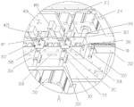
the multi-directional punching mechanism comprises a mounting plate, a plurality of punching components, a die seat and a die core, wherein the die seat is provided with one or more processing stations, a groove for accommodating the die core is formed in the center of each processing station, processing grooves are formed in the periphery of the groove, the die core is embedded in the die seat, a part groove for placing accessories is formed in the middle of the die seat, each punching component is provided with a punching driving piece, a connecting block and a punching knife, the punching driving pieces are arranged on side plates, the connecting pieces are embedded in the processing grooves and controlled to move along the processing grooves by the punching driving pieces, and the punching knives are arranged at the front ends of the connecting pieces and penetrate through the die cores to extend into the part grooves to synchronously punch the accessories;
the movable material clamping mechanism comprises a cross beam, an XZ axis moving platform arranged on the cross beam, a back plate arranged on the XZ axis moving platform, and a plurality of pneumatic clamping jaws arranged on the back plate, so that the movable material clamping of the accessories among different processing stations is realized;
the milling mechanism is positioned behind the multidirectional punching mechanism and comprises a machining position switching assembly, a groove milling assembly and a linear groove machining assembly, the machining position switching assembly comprises a linear sliding table which is arranged on the machine cabinet and is linearly arranged with a machining station of the multidirectional punching mechanism, the groove milling assembly and the linear groove machining assembly are arranged on one side or two sides of the linear sliding table at intervals, a milling die for loading accessories is arranged on the linear sliding table, and sequential switching is carried out among a loading position, a groove milling position, a linear groove machining position and a blanking position through the linear sliding table;
the reaming mechanism comprises a bearing assembly and a reaming assembly, the bearing assembly is positioned on one side of the linear sliding table and is provided with a pneumatic chuck for clamping accessories and a material ejecting cylinder for ejecting the accessories out, the pneumatic chuck and the returned milling mold are in the same straight line, the reaming function assembly is provided with a lifting cylinder and a drill bit for realizing reaming, and the reaming depth is adjusted up and down by controlling the drill bit through the lifting cylinder;
the movable feeding mechanism comprises a bidirectional adjusting mechanism, a feeding plate and a second pneumatic clamping jaw, the feeding plate is fixed on the bidirectional adjusting mechanism, and the second pneumatic clamping jaw is installed on the back of the feeding plate and clamps and conveys accessories in the milling die to the pneumatic chuck;
the blanking mechanism comprises a blanking track obliquely arranged on the machine cabinet and a blowing air pipe positioned on the pneumatic chuck and opposite to the blanking track.
Preferably, the mold core is embedded in the groove, a part groove for placing accessories is formed in the center of the mold core, openings for the punching knife to insert are formed in the periphery of the mold core corresponding to the machining groove, the openings penetrate through the side wall of the part groove, the accessories are placed in the part groove, and the punching knife penetrates through the openings to realize punching synchronous forming of the side wall of the part.
Preferably, the stamping assembly comprises a first stamping assembly and a second stamping assembly, the first stamping assembly is arranged in the longitudinal processing groove of the die base, and the second stamping assembly is arranged in the transverse processing groove of the die base.
Preferably, the first stamping component comprises a first stamping driving piece, a first connecting block and a stamping knife, the first stamping driving piece is installed on the side plates on two sides of the die base, the first connecting block is embedded in the longitudinal machining groove of the die base, and the first stamping driving piece drives the first connecting block to move along the machining groove in a telescopic mode.
Preferably, the second punching press subassembly includes second punching press driving piece, the linkage board, second connecting block and die cutter, second punching press driving piece is installed on the curb plate, with first punching press driving piece dislocation set, the linkage board alternates and is located between two machining-position progressive in the mould seat, second punching press driving piece is connected to linkage board one end, other end both sides are equipped with the wedge structure, the second connecting block inlays the dress in the horizontal processing inslot of mould seat, the society is owing to linkage board wedge structure complex slant groove on the second connecting block, second punching press driving piece drives the linkage board flexible, make the second connecting block round trip movement in horizontal processing inslot.
Preferably, in the movable clamping mechanism, a plurality of pneumatic clamping jaws are installed on the back plate at intervals through fixing blocks, elastic pressing parts are arranged on the fixing blocks, and the elastic pressing parts are located between the two clamping jaws of the pneumatic clamping jaws.
Preferably, in the movable material clamping mechanism, a long strip-shaped fixing strip is mounted on the back plate, assembling blocks are arranged on the fixing strip at intervals, and the pneumatic clamping jaw is clamped on the assembling blocks.
Preferably, bearing assembly includes the mount pad among the reaming mechanism, and liftout cylinder, pneumatic chuck, and the mount pad is fixed on the rack, and pneumatic chuck is fixed in the mount pad, and the liftout cylinder is located the mount pad bottom, and its liftout pole passes mount pad and pneumatic chuck, and the accessory that will process the completion is ejecting, reaming functional component includes the lift cylinder, installs the fixed plate on the lift cylinder, vertical reaming motor of installing on the fixed plate, and installs the drill bit at reaming motor front end, and directly over the drill bit was located pneumatic chuck, and reaming motor drive drill bit is rotatory in order to carry out reaming processing to the accessory in the pneumatic chuck.
Preferably, the reaming motor is transversely installed, the saw blade or the chamfering tool is installed at the front end of the reaming motor, and the cross groove machining or the chamfering machining is carried out on the accessory
Preferably, bearing assembly among the reaming mechanism includes the second mount pad, and pneumatic rotatory chuck, second liftout cylinder, driving motor, and the second mount pad is fixed on the rack, and pneumatic rotatory chuck cooperation rotating member is fixed on the second mount pad, and driving motor fixes on the second mount pad, and its output shaft passes through the belt to be connected with the rotating member for driving motor drives pneumatic rotatory chuck rotatory, second liftout cylinder is fixed at the second mounting panel back, and its liftout pole passes the rotating member when stretching out and inserts in the pneumatic rotatory chuck, and the accessory that will process is ejecting, the reaming subassembly includes lift cylinder, fixed plate, drill bit mounting bracket and drill bit, and the fixed plate is installed on lift cylinder, and the drill bit passes through the drill bit mounting bracket to be fixed on the fixed plate, lift cylinder control drill bit reciprocates, and pneumatic rotatory chuck centre gripping accessory is rotatory, realizes the reaming processing.
Compared with the prior art, the invention has the following beneficial effects:
the flexibility, one or more processing stations can be selected for punching processing according to the processing complexity of the accessories for continuous processing, so that the processing flexibility of the punching machine is improved;
the punching air cylinders can be arranged in two directions by adopting the inclined grooves matched with the wedge-shaped structure, punching power is provided in four directions, and the problem that the air cylinders are difficult to be arranged in four directions by a plurality of processing stations is effectively solved;
the punching mechanism and the milling mechanism are in a linear compact layout, seamless switching of accessories from a punching station to a milling station can be realized through a group of pneumatic clamping jaws, an intermediate transition structure is not needed, and the machining efficiency is improved;
elastic pressing parts are arranged in the pneumatic clamping jaws, downward pressing of the placed accessories is achieved, the accessories are completely placed in the part grooves, and therefore accuracy of machining size is guaranteed;
the complex parts are subjected to decomposition of processing grooves by adopting a plurality of stations, holes in different directions are processed by different stations, and then the integrated processing of punching, milling and chambering is realized by combining milling groove structures in a plurality of positions and a drilling mechanism, so that not only is the processing of the complex parts realized, but also the continuous high-efficiency processing is realized, the reaming mechanism at the tail end can be replaced according to the processing requirements, and various processing such as grooving or chamfering can be realized by matching with different processing heads;
the design of various hole expanding structures can realize the processing of different holes, and the comprehensiveness of equipment processing is improved;
adopt vibration dish cooperation material loading track to realize automatic feeding operation, adopt unloading mechanism to realize automatic unloading, adopt a plurality of cylinders cooperation electric cabinet to realize the automatic control that punches a hole, promote the automation of whole equipment, reduce manual operation's potential safety hazard, promote machining efficiency.
Drawings
FIG. 1 is a first schematic structural diagram according to an embodiment of the present invention;
FIG. 2 is a second schematic structural diagram according to an embodiment of the present invention;
FIG. 3 is a third schematic structural diagram according to an embodiment of the present invention;
FIG. 4 is an enlarged view of FIG. 1 at C;
FIG. 5 is an enlarged view of FIG. 1 at D;
FIG. 6 is an enlarged view of the point A in FIG. 2;
FIG. 7 is an enlarged view of the point B in FIG. 2;
FIG. 8 is an exploded view of the assembly of the linkage plate ends in an embodiment of the present invention;
FIG. 9 is a block diagram of a tooling position switching assembly in an embodiment of the present invention;
FIG. 10 is a partial schematic view of an alternative form of mounting of the pneumatic clamp jaws of the disclosed embodiment;
FIG. 11 is a first block diagram of another reaming assembly in accordance with an embodiment of the present invention;
FIG. 12 is a block diagram of another alternative reaming assembly in accordance with an embodiment of the present invention;
FIG. 13 is a variation of the process for machining a part.
In the figure: 1-cabinet, 2-vibration feeding mechanism, 3-multidirectional punching mechanism, 4-movable clamping mechanism, 5-milling mechanism, 6-movable feeding mechanism, 7-hole expanding mechanism, 8-blanking mechanism, 9-electric cabinet, 10-fittings, 201-vibration disc, 202-feeding track, 203-limiting air cylinder, 301-mounting plate, 302-first punching component, 303-second punching component, 304-die seat, 305-die core, 306-support column, 307-processing groove, 308-slotted hole, 309-parts groove, 310-first punching driving piece, 311-first connecting block, 312-punching knife, 313-side plate, 314-second punching driving piece, 315-linkage plate, 316-second connecting block, 317-wedge structure, 318-oblique groove, 319-third material ejecting cylinder, 401-beam, 402-XZ axis moving platform, 403-back plate, 404-pneumatic clamping jaw, 405-upright post, 406-first linear module, 407-transverse moving cylinder, 408-second linear module, 409-vertical moving cylinder, 410-fixed block, 411-elastic material pressing piece, 412-fixed strip, 413-assembly block, 501-linear sliding table, 502-milling mould, 503-second part groove, 504-notch, 505-first YZ axis moving platform, 506-milling groove motor, 507-milling cutter, 508-second YZ axis moving platform, 509-linear groove processing motor, 510-saw blade, 601-second lifting cylinder, 602-second linear sliding table, 603-a feeding plate, 604-a second pneumatic clamping jaw, 701-a mounting seat, 702-a material ejecting cylinder, 703-a pneumatic chuck, 704-a cross fine adjustment mechanism, 705-a lifting cylinder, 706-a fixing plate, 707-a hole expanding motor, 708-a drill bit, 709-a second mounting seat, 710-a pneumatic rotary chuck, 711-a second material ejecting cylinder, 712-a driving motor, 713-a rotating member, 714-a second gear, 715-a drill bit mounting frame, 801-a material blowing air pipe and 802-a blanking track.
Detailed Description
The technical solutions in the embodiments of the present invention will be clearly and completely described below with reference to the drawings in the embodiments of the present invention, and it is obvious that the described embodiments are only a part of the embodiments of the present invention, and not all of the embodiments.
The invention discloses a punching, milling and drilling integrated machine, which can realize synchronous processing of a plurality of directional holes, grooves and chambering on the side wall of an atomizing core accessory and realize automatic feeding and discharging operations, the processing change of the accessory is shown in figure 13, the structure of the integrated machine is shown in figures 1-10, the integrated machine comprises a cabinet 1, a vibration feeding mechanism 2 installed on the cabinet, a multidirectional punching mechanism 3, a movable clamping mechanism 4, a milling mechanism 5, a movable feeding mechanism 6, a chambering mechanism 7, a blanking mechanism 8 and an electric cabinet 9, the vibration feeding mechanism carries out vibration feeding on the accessory 10, the movable clamping mechanism clamps and sends the accessory to be processed to the multidirectional punching mechanism for punching processing, then the movable clamping mechanism transfers the accessory subjected to hole punching to a station switching mechanism, the plurality of milling mechanisms are switched through the station switching mechanism to process different milling grooves, the milled accessory is sent to the chambering position through the movable feeding mechanism for chambering, the blanking mechanism carries out automatic discharging operations after chambering is finished, and the multidirectional punching mechanism, the vibration feeding mechanism, the punching mechanism, the station, the switching mechanism, the chambering mechanism and the blanking mechanism are designed in a straight line on the cabinet, and the integrated machine can realize linear processing of the accessories.
Specifically speaking, the rack can select horizontal or vertical as required, vibration feed mechanism includes vibration dish 201 and material loading track 202, the vibration dish is through fixing on the rack, material conveying channel is equipped with to material loading track inside, and its one end transversely extends to in the vibration dish, and the accessory of being convenient for in the vibration dish gets into gradually, and the other end extends to removal clamping mechanism department, is a sharp setting with diversified mechanism of punching a hole, and material loading track side is provided with spacing cylinder 203, through spacing cylinder's flexible control, ensures that only one accessory gets into material conveying channel top at every turn to the smoothness nature of the material of guaranteeing to clamp at every turn.
The multidirectional punching mechanism comprises a mounting plate 301, a plurality of first punching assemblies 302, a plurality of second punching assemblies 303, a die seat 304 and a die core 305, wherein the mounting plate is fixed on a cabinet through a support 306, the die seat is fixed on the mounting plate, one machining station or a plurality of machining stations are set on the die seat as required, a groove for accommodating the die core is formed in the center of each machining station, machining grooves 307 are formed in the periphery of the groove, the two longitudinal groups of machining grooves extend to the side face of the die seat and are communicated with each other, slotted holes 308 penetrating in the longitudinal direction are formed in the die seat and are located on the two transverse sides of the groove, the die core is embedded in the groove, a part groove 309 for placing accessories is formed in the center of the die core, openings for the punching assemblies to insert are formed in the positions, corresponding to the machining grooves, of the die core are communicated with the side walls of the part groove, the accessories are placed in the part groove, punching and are clamped by the punching assemblies in order to move the clamping mechanism after punching is completed, a third ejecting cylinder 319 is arranged in the position corresponding to the back of the mounting plate, and the parts groove for ejecting the completed.
First punching press subassembly includes first punching drive spare 310, first connecting block 311 and die cutter 312, the curb plate 313 outside at the die holder both sides is installed to first punching drive spare, and its flexible end is connected with the die cutter through first connecting block, and just first connecting block inlays the dress and makes a round trip to slide along the processing groove in two vertical processing inslots that the recess corresponds, and through first punching drive spare control it, drives the flexible vertical punching operation that carries out the accessory of die cutter, the die cutter can be changed according to the shape in punching a hole or groove, the driving piece that punches a hole can select cylinder, hydro-cylinder or motor drive cam to realize according to accessory material hardness, thickness difference.
The second punching component comprises a second punching driving piece 314, a linkage plate 315, a second connecting block 316 and a punching knife, the second punching driving piece is installed on the inner side of a side plate and is arranged in a staggered mode with the first punching driving piece, one end of the linkage plate is connected with the telescopic end of the second punching driving piece, the other end of the linkage plate is inserted into a slotted hole 308 of the die holder, wedge-shaped structures 317 are arranged on two sides of the front end of the linkage plate, the second connecting block is embedded in two transverse machining grooves corresponding to the grooves, an inclined groove 318 is arranged at one end of the second connecting block and matched with the wedge-shaped structures on the linkage plate, the punching knife is arranged at the other end of the linkage plate, and the second punching driving piece controls the telescopic wedge-shaped structures of the linkage plate to enable the second connecting block to transversely move, so that transverse punching operation of accessories is achieved. Due to the design of the linkage plate oblique sliding structure, the punching cylinders can be arranged in two directions, punching power is provided in four directions, and the problem that the cylinders are difficult to arrange in four directions in multiple machining processes is effectively solved.
The die base can be used for selecting different stations according to the number, the direction and the form of the holes and grooves on the surface of the accessory, if the processing mode is simpler (for example, only one or two surfaces are used for processing the holes and grooves), the die base of one processing station is selected, and the corresponding stamping assembly is fixed according to the direction of the holes and grooves. And to the comparatively complicated processing form of structure (for example three more than carry out slotted hole processing, perhaps will carry out two slotted hole processing etc. on one face), just need to set up a plurality of processing stations, utilize different stations to carry out the slotted hole processing in different position, this kind of continuous stamping, can avoid the problem that the slotted hole in a plurality of positions can't be processed simultaneously to less part, to other more complicated structures, only need carry out the change of different position punching press subassemblies according to position condition and the mutual position condition of slotted hole to realize the processing of complex structure.
The movable clamping mechanism 4 comprises a cross beam 401, an XZ-axis moving platform 402, a back plate 403 and a plurality of pneumatic clamping jaws 404, wherein the cross beam is installed on an installation plate through two upright posts 405, the XZ-axis moving platform is installed on the cross beam, the XZ-axis moving platform belongs to the existing conventional structure and generally comprises a first linear module 406 and a transverse moving cylinder 407 which can realize transverse movement, a second linear module 408 and a vertical moving cylinder 409 which can realize lifting, the first linear module is installed on the cross beam, the second linear module is installed on a sliding block of the first linear module, the back plate is installed on a sliding block of the second linear module, the plurality of pneumatic clamping jaws are installed on the back plate at intervals through intermediate pieces, the interval distance between each other is consistent with the interval distance between a plurality of processing stations on a multi-directional punching mechanism, the switching between the processing stations and clamping positions is realized through the transverse moving cylinder during use, so that the accessories are transferred, and the vertical moving cylinder realizes the operation of clamping and discharging up and down.
The mounting mode of pneumatic clamping jaw can have a variety, for example through fixed block 410 installation, every pneumatic clamping jaw is furnished with a fixed block, in order to ensure that the accessory gets into the part groove completely after pneumatic clamping jaw loosens, set up elasticity pressure material piece 411 additionally on the fixed block, make it be located between two clamping jaws of pneumatic clamping jaw, realize pressing down the supplementary of accessory, the structure of specific elasticity pressure material piece includes presses material piece and spring, presses material piece slidable mounting on the fixed block, the spring is as for pressing between material piece and the pneumatic clamping jaw, this structure is conventional elasticity swager to construct.
The pneumatic clamping device can also be provided with a long fixing strip 412, the fixing strip is provided with assembling blocks 413 at intervals, and the pneumatic clamping jaws are clamped in the assembling blocks, so that the fixing strip is suitable for the condition that the number of stations is large (more than four stations), and the stability of transverse movement can be guaranteed (as shown in fig. 9).
The quantity of pneumatic clamping jaw is one more than machining position number all the time, can realize like this that the station of punching a hole gets to the direct clamp of milling the station and gets and transport, avoids middle transition region, has promoted the effect of transporting, ensures the continuity work of machine simultaneously
Processing position switching subassembly realizes the switching of processing position in this mechanism, and is initial, the milling mold removes to foremost (material loading level), the accessory clamp that has washed the hole in with the mold core by removing the pneumatic clamping jaw that presss from both sides material mechanism presss from both sides and gets and put into the second part inslot, synchronous motion sharp slip table, make the milling mold remove in proper order and carry out corresponding processing to milling groove subassembly (milling groove position) and a line groove processing subassembly (a line groove adds the station) department, processing is accomplished back sharp slip table and will be milled the mold and remove to rearmost (unloading position), send the accessory that mills the completion to reaming mechanism department through removing feeding mechanism and process.
The reaming mechanism is located at one side of the tail end of the linear sliding table and comprises a bearing component and a reaming component, wherein the bearing component is used for loading a to-be-reamed accessory, the reaming component is used for drilling the accessory, the reaming component is arranged at one end of a rotary drive for the conventional straight cylinder hole, the bearing component only achieves the clamping effect, the specific structure is shown in figures 1-2, the bearing component comprises an installation seat 701, a material ejecting cylinder 702 and a pneumatic chuck 703, the installation seat is fixed on a machine cabinet, the pneumatic chuck is fixed in the installation seat, the clamping or loosening of the accessory is achieved, the material ejecting cylinder is located at the bottom of the installation seat, an ejecting rod of the material ejecting cylinder penetrates through the installation seat and the pneumatic chuck, the machined accessory is ejected out, the blanking is facilitated, the pneumatic chuck and a milling die behind the pneumatic chuck are located on the same straight line, and the feeding mechanism can be conveniently moved to achieve the straight line feeding.
The reaming functional component comprises a cross fine adjustment mechanism 704, a lifting cylinder 705, a fixing plate 706, a reaming motor 707 and a drill bit 708, wherein the lifting cylinder is installed on the cross fine adjustment mechanism, the fixing plate is installed on the lifting cylinder and is controlled to lift, the reaming motor is installed on the fixing plate, the drill bit is installed at the front end of the reaming motor, the drill bit drilling position is adjusted through the cross fine adjustment mechanism, the drill bit is located right above a pneumatic chuck, the reaming motor is controlled to drive the drill bit to rotate, the lifting cylinder is synchronously controlled to lift, and reaming processing is carried out on accessories in the pneumatic chuck.
The processing of a non-straight cylindrical hole such as a stepped hole needs to be realized by adopting the structure shown in fig. 11 to 12, the bearing component includes a second mounting seat 709, a pneumatic rotating chuck 710, a second material ejecting cylinder 711, a driving motor 712, the second mounting seat is fixed on the cabinet, the pneumatic rotating chuck is fixed on the second mounting seat in cooperation with a rotating member 714, the rotating driving member is a hollow rotating shaft, a gear is sleeved on the rotating shaft, the driving motor is fixed on the second mounting seat, a second gear 715 is sleeved on an output shaft of the driving motor, the second gear is connected with the gear on the rotating shaft through a belt (not shown), so that the driving motor drives the pneumatic rotating chuck to rotate, the second material ejecting cylinder is fixed on the back of the second mounting plate, and an ejecting rod of the second material ejecting cylinder penetrates through the rotating shaft to be inserted into the pneumatic rotating chuck when extending out, so as to eject out a processed accessory.
The reaming subassembly includes cross fine-tuning 704, lift cylinder 705, fixed plate 706, drill bit mounting bracket 716 and drill bit 708, the lift cylinder is installed on cross fine-tuning, the fixed plate is installed on the lift cylinder, by its control lift operation, the drill bit passes through the drill bit mounting bracket to be fixed on the fixed plate, carry out drill bit drilling position control through cross fine-tuning, make it be located pneumatic rotatory chuck directly over, lift cylinder control drill bit reciprocates during processing, and driving motor drives pneumatic rotatory chuck and rotates, realize the rotatory reaming of accessory, the regulation of drilling position can be realized to this kind of structure, thereby realize the processing in other types of hole.
The movable feeding mechanism is located at the tail end of the machining position switching assembly, accessory clamping in the milling mold is conveyed to a pneumatic chuck, the movable feeding mechanism structurally comprises a second lifting cylinder 601, a second linear sliding table 602, a feeding plate 603 and a second pneumatic clamping jaw 604, the feeding plate is fixed on the second linear sliding table on which the second lifting cylinder is installed, the second pneumatic clamping jaw is installed on the back face of the feeding plate, the whole process is that the second linear sliding table controls the second pneumatic clamping jaw to move to the position right above the milling mold, the second lifting cylinder lifts and enables the second pneumatic clamping jaw to clamp and lift the accessory downwards, then the second linear sliding table controls the second pneumatic clamping jaw to move to the position right above the pneumatic chuck, the second lifting cylinder controls the second pneumatic clamping jaw to transfer the accessory, and the accessory is conveyed at two positions in a reciprocating mode.
The unloading mechanism is installed at the end, realizes the unloading to the accessory after processing, and it can be set for multiple form according to the accessory characteristic, if blow the unloading form, perhaps this embodiment is the initial stage unloading form, including blowing material trachea 801 and installing in pneumatic chuck department, still include that unloading track 802 is located the relative direction of blowing the material trachea, and the accessory that the processing was accomplished is ejecting through the liftout cylinder, blows the material trachea and blows out high-pressure gas, blows the accessory and carries out the unloading in the unloading track.
The electric cabinet is arranged on the frame and used for controlling different cylinders to work correspondingly.
The invention discloses a punching, milling and drilling integrated machine, which has the working principle that: the accessories are vibrated in a vibration disc and enter a feeding rail, one accessory is pushed to the end of the feeding rail, a transverse moving cylinder moves a pneumatic clamping jaw to a first position, namely, the rightmost pneumatic clamping jaw is positioned above the tail end of the feeding rail, the leftmost mechanical jaw is positioned above the leftmost processing station, a vertical moving cylinder drives the pneumatic clamping jaw to move downwards to clamp the accessory, the transverse moving cylinder moves to a second position, the clamped accessory is sent into the processing station to be punched, then the pneumatic clamping jaw is transferred into the left processing station to be punched in other directions, after punching is completed, the pneumatic clamping jaw on the transverse moving cylinder gradually sends the punched accessory into a second part groove of a milling die, a linear sliding table moves horizontally, the milling die is gradually sent to each milling cutter or a word groove to be milled, after milling is completed, the linear sliding table moves to the tail, the accessory is sent to be reamed by a movable feeding mechanism to be reamed and processed, blanking is achieved by a blanking mechanism after reaming processing is completed, the whole processing process is achieved, and the line arrangement is reasonable, and multiple processing forms of full-automatic punching and drilling can be achieved.
The above description is only for the preferred embodiment of the present invention, but the scope of the present invention is not limited thereto, and any person skilled in the art should be considered to be within the technical scope of the present invention, and the technical solutions and the inventive concepts thereof according to the present invention should be equivalent or changed within the scope of the present invention.
Claims (10)
1. The utility model provides a dash and mill processing all-in-one that bores which characterized in that: including the rack, install vibration feed mechanism in the frame, diversified punching mechanism removes clamping mechanism, mills the mechanism, removes feeding mechanism, reaming mechanism and unloading mechanism, wherein:
the vibration feeding mechanism comprises a vibration disc and a feeding track, one end of the feeding track is transversely arranged in the vibration disc, the other end of the feeding track extends to the position of the movable material clamping mechanism, and accessories are fed into the multi-directional punching mechanism one by one;
the multi-directional punching mechanism comprises a mounting plate, a plurality of punching components, a die seat and a die core, wherein the die seat is provided with one or more processing stations, a groove for accommodating the die core is formed in the center of each processing station, processing grooves are formed in the periphery of the groove, the die core is embedded in the die seat, a part groove for placing accessories is formed in the middle of the die seat, each punching component is provided with a punching driving piece, a connecting block and a punching knife, the punching driving pieces are arranged on side plates, the connecting pieces are embedded in the processing grooves and controlled to move along the processing grooves by the punching driving pieces, and the punching knives are arranged at the front ends of the connecting pieces and penetrate through the die cores to extend into the part grooves to synchronously punch the accessories;
the movable material clamping mechanism comprises a cross beam, an XZ axis moving platform arranged on the cross beam, a back plate arranged on the XZ axis moving platform, and a plurality of pneumatic clamping jaws arranged on the back plate, so that the movable material clamping of the accessories among different processing stations is realized;
the milling mechanism is positioned behind the multidirectional punching mechanism and comprises a machining position switching assembly, a groove milling assembly and a linear groove machining assembly, the machining position switching assembly comprises a linear sliding table which is arranged on the machine cabinet and is linearly arranged with a machining station of the multidirectional punching mechanism, the groove milling assembly and the linear groove machining assembly are arranged on one side or two sides of the linear sliding table at intervals, a milling die for loading accessories is arranged on the linear sliding table, and sequential switching is carried out among a feeding position, a groove milling position, a linear groove machining position and a discharging position through the linear sliding table;
the reaming mechanism comprises a bearing assembly and a reaming assembly, the bearing assembly is positioned on one side of the linear sliding table and is provided with a pneumatic chuck for clamping accessories and a material ejecting cylinder for ejecting the accessories, the pneumatic chuck and the returned milling die are positioned on the same straight line, the reaming functional assembly is provided with a lifting cylinder and a drill bit for realizing reaming, and the reaming depth is adjusted up and down by controlling the drill bit through the lifting cylinder;
the movable feeding mechanism comprises a bidirectional adjusting mechanism, a feeding plate and a second pneumatic clamping jaw, the feeding plate is fixed on the bidirectional adjusting mechanism, and the second pneumatic clamping jaw is installed on the back of the feeding plate and clamps and conveys accessories in the milling die to the pneumatic chuck;
the blanking mechanism comprises a blanking track obliquely arranged on the machine cabinet and a blowing air pipe positioned on the pneumatic chuck and opposite to the blanking track.
2. The punching, milling, drilling and machining all-in-one machine as claimed in claim 1, wherein: the die core is embedded in the groove, the center of the die core is provided with a part groove for placing accessories, the periphery of the die core corresponds to the processing groove and is provided with an opening for the punching knife to insert, the opening penetrates through the side wall of the part groove, the accessories are placed in the part groove, and the punching knife penetrates through the opening to realize punching synchronous forming of the side wall of the part.
3. The punching, milling, drilling and machining all-in-one machine as claimed in claim 1, wherein: the stamping assembly comprises a first stamping assembly and a second stamping assembly, the first stamping assembly is installed in a longitudinal machining groove of the die base, and the second stamping assembly is installed in a transverse machining groove of the die base.
4. The punching, milling, drilling and machining all-in-one machine as claimed in claim 3, wherein: the first stamping assembly comprises a first stamping driving piece, a first connecting block and a stamping knife, the first stamping driving piece is installed on the side plates on two sides of the die seat, the first connecting block is embedded in a longitudinal machining groove of the die seat, and the first stamping driving piece drives the first connecting block to move along the machining groove in a telescopic mode.
5. The punching, milling, drilling and machining all-in-one machine as claimed in claim 4, wherein: the second punching press subassembly includes second punching press driving piece, the linkage board, second connecting block and stamping knife, second punching press driving piece is installed on the curb plate, with first punching press driving piece dislocation set, the linkage board alternates and is located between two machining-position in the mould seat, second punching press driving piece is connected to linkage board one end, the other end both sides are equipped with the wedge structure, the second connecting block inlays the dress and in the horizontal processing inslot of mould seat, the society is because linkage board wedge structure complex slant groove on the second connecting block, second punching press driving piece drives the linkage board flexible, make the second connecting block at horizontal processing inslot round trip movement.
6. The punching, milling, drilling and machining all-in-one machine as claimed in claim 1, wherein: in the movable clamping mechanism, a plurality of pneumatic clamping jaws are installed on a back plate at intervals through fixing blocks, elastic pressing parts are arranged on the fixing blocks, and the elastic pressing parts are located between the two clamping jaws of the pneumatic clamping jaws.
7. The punching, milling, drilling and machining all-in-one machine as claimed in claim 1, wherein: in the movable material clamping mechanism, a back plate is provided with a strip-shaped fixing strip, assembling blocks are arranged on the fixing strip at intervals, and a pneumatic clamping jaw is clamped on the assembling blocks.
8. The punching, milling, drilling and machining all-in-one machine as claimed in claim 1, wherein: bearing assembly includes the mount pad among the reaming mechanism, and the liftout cylinder, pneumatic chuck, the mount pad is fixed on the rack, and pneumatic chuck is fixed in the mount pad, and the liftout cylinder is located the mount pad bottom, and its liftout pole passes mount pad and pneumatic chuck, and the accessory that will process the completion is ejecting, reaming functional component includes the lift cylinder, installs the fixed plate on the lift cylinder, vertically installs the reaming motor on the fixed plate, and installs the drill bit at reaming motor front end, directly over the drill bit is located pneumatic chuck, and reaming motor drive drill bit is rotatory in order to carry out reaming processing to the accessory in the pneumatic chuck.
9. The punching, milling, drilling and machining all-in-one machine of claim 8, wherein: the reaming motor is transversely installed, the front end of the reaming motor is provided with a saw blade or a chamfering tool, and the accessory is subjected to cross groove machining or chamfering machining.
10. The punching, milling, drilling and machining all-in-one machine as claimed in claim 1, wherein: bearing assembly among the reaming mechanism includes the second mount pad, and pneumatic rotatory chuck, second liftout cylinder, driving motor, second mount pad are fixed on the rack, and pneumatic rotatory chuck cooperation rotating member is fixed on the second mount pad, and driving motor fixes on the second mount pad, and its output shaft passes through the belt to be connected with the rotating member for driving motor drives pneumatic rotatory chuck rotatory, second liftout cylinder is fixed at the second mounting panel back, and its liftout pole passes the rotating member when stretching out and inserts in the pneumatic rotatory chuck, and the accessory that will process is ejecting, the reaming subassembly includes lift cylinder, fixed plate, drill bit mounting bracket and drill bit, and the fixed plate is installed on lift cylinder, and the drill bit passes through the drill bit mounting bracket to be fixed on the fixed plate, lift cylinder control drill bit reciprocates, and pneumatic rotatory chuck centre gripping accessory is rotatory, realizes the reaming processing.
Priority Applications (1)
| Application Number | Priority Date | Filing Date | Title |
|---|---|---|---|
| CN202210903612.6A CN115255940B (en) | 2022-07-28 | 2022-07-28 | Punching, milling and drilling integrated machine |
Applications Claiming Priority (1)
| Application Number | Priority Date | Filing Date | Title |
|---|---|---|---|
| CN202210903612.6A CN115255940B (en) | 2022-07-28 | 2022-07-28 | Punching, milling and drilling integrated machine |
Publications (2)
| Publication Number | Publication Date |
|---|---|
| CN115255940A true CN115255940A (en) | 2022-11-01 |
| CN115255940B CN115255940B (en) | 2023-06-20 |
Family
ID=83771091
Family Applications (1)
| Application Number | Title | Priority Date | Filing Date |
|---|---|---|---|
| CN202210903612.6A Active CN115255940B (en) | 2022-07-28 | 2022-07-28 | Punching, milling and drilling integrated machine |
Country Status (1)
| Country | Link |
|---|---|
| CN (1) | CN115255940B (en) |
Cited By (1)
| Publication number | Priority date | Publication date | Assignee | Title |
|---|---|---|---|---|
| CN116276125A (en) * | 2023-05-17 | 2023-06-23 | 长玲自动化装备(常州)有限公司 | Full-automatic production line and production process for handlebar upright rods |
Citations (5)
| Publication number | Priority date | Publication date | Assignee | Title |
|---|---|---|---|---|
| WO1997010071A1 (en) * | 1995-09-14 | 1997-03-20 | Wenyuan Shao | A composite-machining center |
| CN108788751A (en) * | 2018-07-05 | 2018-11-13 | 东莞市克诺五金有限公司 | Full-automatic cun five mainboards scrape burr machine |
| CN210306710U (en) * | 2019-11-23 | 2020-04-14 | 苏州网宏自动化设备有限公司 | Automatic punching, milling and drilling integrated equipment for communication product shell |
| CN213105525U (en) * | 2020-04-09 | 2021-05-04 | 佛山市顺德区宣美机械设备有限公司 | Saw is dashed brill and is milled turn-up all-in-one |
| CN114210852A (en) * | 2021-12-21 | 2022-03-22 | 深圳市正良制品有限公司 | Punching and milling integrated machine |
-
2022
- 2022-07-28 CN CN202210903612.6A patent/CN115255940B/en active Active
Patent Citations (5)
| Publication number | Priority date | Publication date | Assignee | Title |
|---|---|---|---|---|
| WO1997010071A1 (en) * | 1995-09-14 | 1997-03-20 | Wenyuan Shao | A composite-machining center |
| CN108788751A (en) * | 2018-07-05 | 2018-11-13 | 东莞市克诺五金有限公司 | Full-automatic cun five mainboards scrape burr machine |
| CN210306710U (en) * | 2019-11-23 | 2020-04-14 | 苏州网宏自动化设备有限公司 | Automatic punching, milling and drilling integrated equipment for communication product shell |
| CN213105525U (en) * | 2020-04-09 | 2021-05-04 | 佛山市顺德区宣美机械设备有限公司 | Saw is dashed brill and is milled turn-up all-in-one |
| CN114210852A (en) * | 2021-12-21 | 2022-03-22 | 深圳市正良制品有限公司 | Punching and milling integrated machine |
Cited By (2)
| Publication number | Priority date | Publication date | Assignee | Title |
|---|---|---|---|---|
| CN116276125A (en) * | 2023-05-17 | 2023-06-23 | 长玲自动化装备(常州)有限公司 | Full-automatic production line and production process for handlebar upright rods |
| CN116276125B (en) * | 2023-05-17 | 2023-08-18 | 长玲自动化装备(常州)有限公司 | Full-automatic production line and production process for handlebar upright rods |
Also Published As
| Publication number | Publication date |
|---|---|
| CN115255940B (en) | 2023-06-20 |
Similar Documents
| Publication | Publication Date | Title |
|---|---|---|
| CN111890051B (en) | High efficiency digit control machine tool | |
| CN201070684Y (en) | Lock body punch | |
| CN209223665U (en) | Digital-control two-head composite processing machine tool | |
| CN114210852A (en) | Punching and milling integrated machine | |
| CN116937285B (en) | Pin molding equipment and method thereof | |
| CN115255940B (en) | Punching, milling and drilling integrated machine | |
| CN216420874U (en) | Punching and milling integrated machine | |
| CN111843514A (en) | Continuous processing equipment for probe | |
| CN205660388U (en) | Axle class beveler that radially punches | |
| CN215697268U (en) | Automatic punching machine | |
| CN113414286B (en) | Automatic punching machine | |
| CN210413461U (en) | Drilling and tapping combined machining machine tool | |
| CN212665422U (en) | Continuous processing equipment for probe | |
| CN218533521U (en) | Punching, milling and drilling integrated machine | |
| CN211916072U (en) | Integrated equipment for precision engraving, drilling and milling | |
| CN117245742A (en) | Double-five-axis machining center for machining strip-shaped materials into special-shaped pieces | |
| CN214053713U (en) | High-efficient type double-screw hole drilling equipment | |
| CN212019481U (en) | Precision punching machine for round shaft type grinding parts | |
| CN215091468U (en) | Multi-station multi-material-level bracket connecting piece production line | |
| CN218136276U (en) | Atomizing core accessory integration processing equipment | |
| CN219881881U (en) | Hinge type clamping tool | |
| CN115846509A (en) | Multifunctional integrated processing equipment | |
| CN217700954U (en) | Device for simultaneously processing window holes of different specifications | |
| CN219633064U (en) | Automatic rack inserting machine component | |
| CN218427156U (en) | Feeding device of contact tube perforating machine and perforating machine |
Legal Events
| Date | Code | Title | Description |
|---|---|---|---|
| PB01 | Publication | ||
| PB01 | Publication | ||
| SE01 | Entry into force of request for substantive examination | ||
| SE01 | Entry into force of request for substantive examination | ||
| GR01 | Patent grant | ||
| GR01 | Patent grant |