CN115231814A - Original tempered glass sheet opening device - Google Patents
Original tempered glass sheet opening device Download PDFInfo
- Publication number
- CN115231814A CN115231814A CN202210864600.7A CN202210864600A CN115231814A CN 115231814 A CN115231814 A CN 115231814A CN 202210864600 A CN202210864600 A CN 202210864600A CN 115231814 A CN115231814 A CN 115231814A
- Authority
- CN
- China
- Prior art keywords
- plate
- spring
- sliding
- rotating
- toughened glass
- Prior art date
- Legal status (The legal status is an assumption and is not a legal conclusion. Google has not performed a legal analysis and makes no representation as to the accuracy of the status listed.)
- Granted
Links
- 239000005341 toughened glass Substances 0.000 title claims abstract description 83
- 230000002146 bilateral effect Effects 0.000 claims abstract description 4
- 230000007246 mechanism Effects 0.000 claims description 65
- 238000001125 extrusion Methods 0.000 claims description 2
- 239000011521 glass Substances 0.000 claims description 2
- 239000002243 precursor Substances 0.000 claims 4
- 230000000694 effects Effects 0.000 description 6
- 230000009471 action Effects 0.000 description 5
- 230000000903 blocking effect Effects 0.000 description 3
- 230000008859 change Effects 0.000 description 1
- 230000008878 coupling Effects 0.000 description 1
- 238000010168 coupling process Methods 0.000 description 1
- 238000005859 coupling reaction Methods 0.000 description 1
- 230000007547 defect Effects 0.000 description 1
- 230000003028 elevating effect Effects 0.000 description 1
- 230000001771 impaired effect Effects 0.000 description 1
- 238000000034 method Methods 0.000 description 1
- 230000008569 process Effects 0.000 description 1
Images


Classifications
-
- C—CHEMISTRY; METALLURGY
- C03—GLASS; MINERAL OR SLAG WOOL
- C03B—MANUFACTURE, SHAPING, OR SUPPLEMENTARY PROCESSES
- C03B33/00—Severing cooled glass
- C03B33/02—Cutting or splitting sheet glass or ribbons; Apparatus or machines therefor
- C03B33/023—Cutting or splitting sheet glass or ribbons; Apparatus or machines therefor the sheet or ribbon being in a horizontal position
- C03B33/03—Glass cutting tables; Apparatus for transporting or handling sheet glass during the cutting or breaking operations
-
- C—CHEMISTRY; METALLURGY
- C03—GLASS; MINERAL OR SLAG WOOL
- C03B—MANUFACTURE, SHAPING, OR SUPPLEMENTARY PROCESSES
- C03B33/00—Severing cooled glass
- C03B33/02—Cutting or splitting sheet glass or ribbons; Apparatus or machines therefor
- C03B33/023—Cutting or splitting sheet glass or ribbons; Apparatus or machines therefor the sheet or ribbon being in a horizontal position
- C03B33/037—Controlling or regulating
-
- C—CHEMISTRY; METALLURGY
- C03—GLASS; MINERAL OR SLAG WOOL
- C03B—MANUFACTURE, SHAPING, OR SUPPLEMENTARY PROCESSES
- C03B33/00—Severing cooled glass
- C03B33/10—Glass-cutting tools, e.g. scoring tools
-
- Y—GENERAL TAGGING OF NEW TECHNOLOGICAL DEVELOPMENTS; GENERAL TAGGING OF CROSS-SECTIONAL TECHNOLOGIES SPANNING OVER SEVERAL SECTIONS OF THE IPC; TECHNICAL SUBJECTS COVERED BY FORMER USPC CROSS-REFERENCE ART COLLECTIONS [XRACs] AND DIGESTS
- Y02—TECHNOLOGIES OR APPLICATIONS FOR MITIGATION OR ADAPTATION AGAINST CLIMATE CHANGE
- Y02P—CLIMATE CHANGE MITIGATION TECHNOLOGIES IN THE PRODUCTION OR PROCESSING OF GOODS
- Y02P40/00—Technologies relating to the processing of minerals
- Y02P40/50—Glass production, e.g. reusing waste heat during processing or shaping
- Y02P40/57—Improving the yield, e-g- reduction of reject rates
Abstract
The invention relates to a medium opening device, in particular to a medium opening device for a toughened glass original sheet. The toughened glass original piece opening device can adjust the position of the cutting knife and is more convenient for people to use. A tempered glass original piece opening device comprises a placing plate, a supporting frame, a sliding block, a first spring, a cross rod and the like; place board downside bilateral symmetry and be connected with the support frame, place the board about the equal slidingtype in both parts be connected with the carriage, all slidingtype are connected with the slider on the carriage, all are connected with first spring between slider and the adjacent carriage, control and be connected with the horizontal pole between two sliders. The former piece of toughened glass is put on placing the board, compresses tightly it through the clamp plate, then staff control cutting knife lapse and the former piece contact of toughened glass, slides forward through driving motor control carriage, and then the drive cutting knife moves forward and cuts the former piece of toughened glass, and because the cutting knife can carry out the horizontal slip, can adjust the cutting position as required.
Description
Technical Field
The invention relates to a medium opening device, in particular to a medium opening device for a toughened glass original sheet.
Background
The original tempered glass sheet is cut into pieces, namely glass is cut, the original tempered glass sheet needs to be cut in the process of processing the tempered glass, the tempered glass sheet is processed into tempered glass with a certain specification, and when the original tempered glass sheet is cut, a medium opening device needs to be used.
Patent grant publication number is CN 216738068U's patent has announced a toughened glass cutting device, and this cutting device includes the cutting equipment body, fixed mounting has the connecting rod on the cutting equipment body, and pole in the inside sliding connection of connecting rod has, and the inside fixed mounting of interior pole has the axis of rotation, and the cutting knife has been cup jointed in the surface rotation of axis of rotation, and the top fixed mounting of interior pole has the slide, slide sliding connection on the inner wall of connecting rod. This toughened glass cutting device, interior pole resets through reset spring, and then makes the cutting knife all the time with toughened glass's surface contact, and then cuts wave toughened glass, and the convenience is cut wavy toughened glass, and then improve device's application scope, improves the effect to the toughened glass cutting, can also cushion with the toughened glass contact suddenly at the cutting knife simultaneously, and then prevents that the cutting knife from breaking toughened glass, avoids toughened glass broken. But this cutting device can not adjust the position of cutting knife, can't adjust the position of cutting the rule according to people's needs, and it is inconvenient to use.
Therefore, the position of the cutting knife can be adjusted, and the toughened glass original piece opening device is convenient for people to use.
Disclosure of Invention
In order to overcome the defects that the position of a cutting knife cannot be adjusted by the existing cutting device, the position of a cutting line cannot be adjusted according to the needs of people, and the use is inconvenient, the technical problem of the invention is as follows: the toughened glass original piece opening device can adjust the position of the cutting knife and is more convenient for people to use.
The utility model provides a device is situated between to former piece of toughened glass, including placing the board, the support frame, the carriage, the slider, first spring, the horizontal pole, the cutting knife, the second spring, hold-down mechanism and actuating mechanism, place board downside bilateral symmetry and be connected with the support frame, it is connected with the carriage to place the equal slidingtype in two portions about the board, it is connected with the slider all to slidingtype on the carriage, all be connected with first spring between slider and the adjacent carriage, it is connected with the horizontal pole to control between two sliders, the slidingtype is connected with the cutting knife on the horizontal pole, be connected with the second spring between cutting knife and the horizontal pole, it is equipped with the hold-down mechanism who is used for compressing tightly the former piece of toughened glass to place on the board, it is equipped with actuating mechanism to place between board and the carriage, actuating mechanism slides around being used for driving the carriage.
In a preferred embodiment of the invention, the pressing mechanism comprises a first sliding rod, a third spring and a pressing plate, the left part and the right part of the placing plate are symmetrically connected with the first sliding rod in a sliding manner, the third spring is connected between the first sliding rod and the placing plate, the pressing plate is connected between the upper parts of the two first sliding rods on the left side and the right side, and the pressing plate moves downwards to press the original piece of tempered glass.
In a preferred embodiment of the invention, the driving mechanism comprises a driving motor, a screw rod and a connecting rod, the driving motor is connected to the front part of the lower side of the placing plate, the screw rod is connected to an output shaft of the driving motor, the connecting rod is connected between the lower sides of the left sliding frame and the right sliding frame, the connecting rod is connected with the screw rod through threads, and the screw rod rotates to drive the connecting rod to move back and forth, so that the sliding frames are driven to slide back and forth.
In a preferred embodiment of the invention, the cutting device further comprises a fixing mechanism for fixing the position of the cutting knife, the fixing mechanism comprises a connecting plate, fixing blocks, a transverse plate, a fourth spring and a stop block, the connecting plate is connected between the left slider and the right slider, a row of fixing blocks are uniformly connected to the connecting plate at intervals, the transverse plate is connected between the rear sides of the row of fixing blocks, the fourth spring is connected between the transverse plate and the connecting plate at the left part and the right part, the stop block is connected to the lower part of the rear side of the sliding frame, the transverse plate moves downwards to be in contact with the stop block, and then is extruded by the stop block to move forwards.
In a preferred embodiment of the invention, the device further comprises a rotating mechanism for driving the toughened glass original sheet to rotate, the rotating mechanism comprises a rotating block, a rotating disc, a gear, a sliding block, a fifth spring, a rack and an L-shaped plate, the rotating block is rotatably connected to the central position of the placing plate, the rotating disc is connected to the upper part of the rotating block, the gear is connected to the lower part of the rotating block through an overrunning clutch, the sliding block is slidably connected to a position on the left side of the placing plate, the fifth spring is connected between the sliding block and the placing plate, the rack is connected to the right part of the sliding block, the rack is meshed with the gear, the L-shaped plate is connected to the left part of the sliding block, and the connecting rod moves forwards to be in contact with the L-shaped plate so as to extrude the L-shaped plate to move forwards.
In a preferred embodiment of the invention, the device further comprises a downward pressing mechanism for automatically moving the pressing plate downward, the downward pressing mechanism comprises a mounting plate, a lower pressing block and a sixth spring, the mounting plate is connected to the lower portion of the sliding frame, the lower pressing blocks are connected to the mounting plate in a sliding manner, the lower pressing blocks move forward and are in contact with the adjacent pressing plates, the pressing plates are further pushed to move downward to press the toughened glass original sheet, and the sixth spring is connected between the lower pressing block and the adjacent mounting plate.
In a preferred embodiment of the present invention, the lifting mechanism is further included for pushing the slider to slide downwards, the lifting mechanism includes a contact rod, a second slide rod, a lifting plate, a seventh spring, a rotating plate and a rotating frame, the contact rod is connected to the slider on the right side, the second slide rod is connected to the right front portion of the placing plate in a sliding manner, the lifting plate is connected to the upper end of the second slide rod, the rear end of the lifting plate is in contact with the contact rod, the seventh spring is connected between the second slide rod and the placing plate, the rotating plate is connected to the right front portion of the placing plate in a rotating manner, the rotating frame is connected to the left portion of the rotating plate, the lifting plate passes through the rotating frame, and the rotating frame rotates to extrude the lifting plate to move downwards.
In a preferred embodiment of the invention, the device further comprises a rubber pad, and the rubber pads are connected to the lower sides of the pressing plates.
The invention has the following advantages: 1. the former piece of toughened glass is put on placing the board, and the clamp plate lapse is compressed tightly it, then staff control cutting knife lapse and the former piece contact of toughened glass, then slide forward through driving motor control carriage, and then the drive cutting knife lapse cuts the former piece of toughened glass, and because the cutting knife can carry out the horizontal slip, can adjust the cutting position as required.
2. After the cutting knife moves to a proper position, the fixing block slides forwards to clamp the cutting knife through the transverse plate and the cooperation of the stop block, and then the position of the cutting knife is fixed.
3. After the cutting knife finishes primary cutting, the connecting rod and the L-shaped plate are matched to enable the rack to drive the gear to rotate, and then the rotating disc drives the toughened glass sheet to rotate to reverse.
4. The lower pressing block moves forwards to be matched with the pressing plate, so that the pressing plate is pushed to move downwards to compress the original toughened glass sheet, and the lower pressing block can upwards slide, so that the device can adapt to the original toughened glass sheets with different thicknesses under the action of the sixth spring.
5. The rotor plate upwards rotates and can make lifter plate extrusion contact pole downstream, and then drives the slider lapse, so, can make things convenient for the staff to control the cutting knife downstream and cut.
Drawings
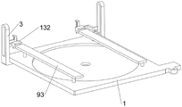
Fig. 1 is a schematic perspective view of the present invention.
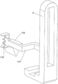
Fig. 2 is a partial perspective view of the present invention.
Fig. 3 is a schematic perspective view of the pressing mechanism of the present invention.
Fig. 4 is a schematic perspective view of the driving mechanism of the present invention.
Fig. 5 is a schematic perspective view of the fixing mechanism of the present invention.
Fig. 6 is a schematic perspective view of a first rotating mechanism of the present invention.
Fig. 7 is a partial perspective view of the rotating mechanism of the present invention.
Fig. 8 is a schematic perspective view of a second rotating mechanism of the present invention.
Fig. 9 is a schematic perspective view of the slider, the rack and the L-shaped plate of the present invention.
Fig. 10 is a schematic perspective view of a first pressing mechanism according to the present invention.
Fig. 11 is a schematic perspective view of a second pressing mechanism according to the present invention.
Fig. 12 is a schematic perspective view of the lifting mechanism of the present invention.
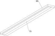
Fig. 13 is a schematic perspective view of the pressing plate and the rubber pad of the present invention.
The parts are numbered as follows: 1: place board, 2: support frame, 3: carriage, 4: slider, 5: first spring, 6: cross-bar, 7: cutting knife, 8: second spring, 9: pressing mechanism, 91: first slide bar, 92: third spring, 93: platen, 10: drive mechanism, 101: drive motor, 102: screw rod, 103: connecting rod, 11: fixing mechanism, 110: connection plate, 111: fixed block, 112: transverse plate, 113: fourth spring, 114: stopper, 12: rotating mechanism, 121: turning block, 122: rotating disk, 123: gear, 124: slider, 125: fifth spring, 126: rack, 127: l-shaped plate, 13: pressing mechanism, 131: mounting plate, 132: briquetting, 133: sixth spring, 14: elevating mechanism, 141: contact stem, 142: second slide bar, 143: lifter plate, 144: seventh spring, 145: rotating plate, 146: rotating frame, 15: and (7) a rubber pad.
Detailed Description
To make the objects, technical solutions and advantages of the present invention more apparent, the present invention will be described in further detail with reference to the accompanying drawings. It is only noted that the invention is intended to be limited to the specific forms set forth herein, including any reference to the drawings, as well as any other specific forms of embodiments of the invention.
Example 1
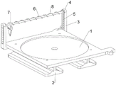
A tempered glass original sheet cutting device is shown in figures 1-4 and comprises a placing plate 1, a supporting frame 2, a sliding frame 3, sliding blocks 4, first springs 5, cross rods 6, cutting knives 7, second springs 8, a pressing mechanism 9 and a driving mechanism 10, wherein the supporting frame 2 is welded on the left side and the right side of the placing plate 1 in a bilateral symmetry mode, the sliding frame 3 is connected to the left side and the right side of the placing plate 1 in a sliding mode, the sliding blocks 4 are connected to the sliding frame 3 in a sliding mode, the first springs 5 are connected between the sliding blocks 4 and the adjacent sliding frame 3, the cross rods 6 are welded between the left sliding blocks 4 and the right sliding blocks 4, the cutting knives 7 are connected to the cross rods 6 in a sliding mode, the second springs 8 are connected between the cutting knives 7 and the cross rods 6, the pressing mechanism 9 is arranged on the placing plate 1, the pressing mechanism 9 can press original tempered glass sheets tightly, the driving mechanism 10 is arranged between the placing plate 1 and the sliding frame 3, and the driving mechanism 10 can drive the sliding frame 3 to slide back and forth.
When the device is used, a worker places an original toughened glass sheet on a placing plate 1, then the worker compresses the original toughened glass sheet through a compressing mechanism 9, then the worker pushes a sliding block 4 to slide downwards, a first spring 5 deforms, the sliding block 4 slides downwards to drive a cross rod 6 to move downwards, the cross rod 6 moves downwards to drive a cutting knife 7 to move downwards, the cutting knife 7 moves downwards to be in contact with the original toughened glass sheet, at the moment, the worker fixes the position of the sliding block 4 through a tool, then the worker drives a sliding frame 3 to slide forwards through a driving mechanism 10, the sliding frame 3 slides forwards to drive the cutting knife 7 to move forwards through the sliding block 4 and the cross rod 6, the cutting knife 7 moves forwards to cut the original toughened glass sheet, meanwhile, the cutting knife 7 can slide left and right on the cross rod 6, the cutting position can be adjusted as required, after cutting is completed, the worker drives the sliding frame 3 to slide backwards through the driving mechanism 10, the cutting knife 7 further enables the cutting knife 7 to move backwards to reset, after the cutting knife 7 moves backwards to reset, the sliding block 4 is loosened by the worker, under the reset action of the first spring 5, the sliding block 4 moves upwards along with the cross rod 6, the cutting knife 7, the other side of the original toughened glass sheet is upwards, and the original toughened glass sheet is loosened by the toughened glass, and the toughened glass sheet is loosened by the toughened glass repeatedly.
As shown in fig. 1 and fig. 3, the pressing mechanism 9 includes a first sliding rod 91, a third spring 92 and a pressing plate 93, the left and right portions of the placing plate 1 are connected with the first sliding rod 91 in a front-back symmetrical sliding manner, the third spring 92 is connected between the first sliding rod 91 and the placing plate 1, and the pressing plate 93 is welded between the two first sliding rods 91 on the left side and the two first sliding rods 91 on the right side.
As shown in fig. 13, a rubber pad 15 is further included, and the rubber pad 15 is connected to the lower side of the pressing plate 93.
When using the device, put the back when the former piece of toughened glass, the staff promotes clamp plate 93 downstream, clamp plate 93 downstream drives first slide bar 91 downslide, deformation takes place for third spring 92, clamp plate 93 compresses tightly the former piece of toughened glass after the downslide, conveniently cut work, under the effect of rubber pad 15, can avoid the former piece of toughened glass impaired, after the cutting is accomplished, the staff loosens clamp plate 93, under the effect that third spring 92 resets, first slide bar 91 drives clamp plate 93 rebound thereupon and resets and loosen the former piece of toughened glass.
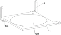
As shown in fig. 1 and 4, the driving mechanism 10 includes a driving motor 101, a lead screw 102 and a connecting rod 103, the driving motor 101 is bolted to the front part of the lower side of the placing plate 1, the output shaft of the driving motor 101 is connected with the lead screw 102 through a coupling, the connecting rod 103 is welded between the lower sides of the left and right sliding frames 3, and the connecting rod 103 is connected with the lead screw 102 through a thread.
When the device is used, the staff starts the driving motor 101, the output shaft of the driving motor 101 rotates to drive the screw rod 102 to rotate, the screw rod 102 rotates to drive the connecting rod 103 to move forwards, the connecting rod 103 moves forwards to drive the sliding frame 3 to slide forwards, and further the cutting knife 7 moves forwards to cut the original toughened glass sheet, after the cutting is completed, the staff controls the reverse rotation of the output shaft of the driving motor 101, the reverse rotation of the output shaft of the driving motor 101 drives the screw rod 102 to rotate backwards, the reverse rotation of the screw rod 102 drives the connecting rod 103 to move backwards, the backward movement of the connecting rod 103 drives the sliding frame 3 to slide backwards, and further the sliding frame 3 drives the cutting knife 7 to move backwards to reset, after the device is used and completed, the staff closes the driving motor 101.
Example 2
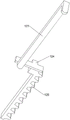
On the basis of embodiment 1, as shown in fig. 1 and 5, the cutting device further comprises a fixing mechanism 11, the fixing mechanism 11 can fix the position of the cutting knife 7, the fixing mechanism 11 comprises a connecting plate 110, fixing blocks 111, a transverse plate 112, a fourth spring 113 and a stop block 114, the connecting plate 110 is welded between the left slider 4 and the right slider 4, the connecting plate 110 is evenly connected with at least two fixing blocks 111 at intervals, the transverse plate 112 is connected between the rear sides of the fixing blocks 111, the fourth spring 113 is connected between the transverse plate 112 and the connecting plate 110 at the left side and the right side, the stop block 114 is installed on the lower portion of the rear side of the sliding frame 3 through bolts, and the transverse plate 112 moves downwards to be in contact with the stop block 114.
When the device is used, a worker pushes the cutting knife 7 to slide rightwards on the cross rod 6, the second spring 8 deforms, after the cutting knife 7 slides to a proper position on the cross rod 6, the worker pushes the slider 4 to slide downwards, the slider 4 slides downwards to enable the cross plate 112 to move downwards through the connecting plate 110 and the fixing block 111, when the cross plate 112 moves downwards to be in contact with the blocking block 114, the cross plate 112 continues to move downwards and can be extruded by the blocking block 114 to move forwards, the fourth spring 113 deforms, the cross plate 112 moves forwards to drive the fixing block 111 to slide forwards, the position of the cutting knife 7 is clamped after the fixing block 111 slides forwards, after cutting is completed, the slider 4 slides upwards to enable the cross plate 112 to move upwards and separate from the blocking block 114, at the moment, under the reset effect of the fourth spring 113, the cross plate 112 drives the cutting knife fixing block 111 to slide backwards along with the cross plate 112, so that the cutting knife 7 is not clamped any more, and at the moment, under the reset effect of the second spring 8, the cutting knife 7 slides leftwards and resets accordingly.
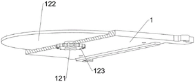
As shown in fig. 1, 6, 7, 8 and 9, the toughened glass sheet placing device further comprises a rotating mechanism 12, the rotating mechanism 12 can drive the toughened glass sheet to rotate, the rotating mechanism 12 comprises a rotating block 121, a rotating disc 122, a gear 123, a sliding block 124, a fifth spring 125, a rack 126 and an L-shaped plate 127, the rotating block 121 is rotatably connected to the central position of the placing plate 1, the rotating disc 122 is welded to the upper part of the rotating block 121, the gear 123 is connected to the lower part of the rotating block 121 through an overrunning clutch, the sliding block 124 is slidably connected to the position, on the left, of the placing plate 1, the fifth spring 125 is connected between the sliding block 124 and the placing plate 1, the rack 126 is welded to the right part of the sliding block 124, the rack sliding block 126 is meshed with the gear 123, the L-shaped plate 127 is welded to the left part of the sliding block 124, and the connecting rod 103 moves forward to be in contact with the L-shaped plate 127.
When the device is used, a worker places a toughened glass original sheet to be cut on the rotating disc 122, when the connecting rod 103 moves forwards to be in contact with the L-shaped plate 127, the cutting knife 7 cuts the toughened glass original sheet once, at the moment, the connecting rod 103 continues to move forwards to drive the L-shaped plate 127 to move forwards, the L-shaped plate 127 moves forwards to drive the sliding block 124 to slide forwards, the sliding block 125 deforms, the sliding block 124 slides forwards to drive the rack 126 to move forwards, the rack 126 moves forwards to drive the gear 123 to rotate, the gear 123 rotates to drive the rotating disc 122 to rotate through the rotating block 121, the rotating disc 122 rotates to drive the toughened glass original sheet to rotate and reverse, when the connecting rod 103 moves backwards, the sliding block 124 drives the rack 126 to move backwards under the reset action of the fifth spring 125, the rack 126 moves backwards to drive the gear 123 to reverse, and the gear 123 reverses under the action of the overrunning clutch and cannot drive the rotating block 121 to reverse, so that the toughened glass original sheet can be automatically reversed after one-time cutting is completed.
As shown in fig. 1, 10 and 11, the device further includes a pressing mechanism 13, the pressing mechanism 13 can automatically move the pressing plate 93 downward, the pressing mechanism 13 includes a mounting plate 131, a pressing block 132 and a sixth spring 133, the mounting plate 131 is welded to the lower portion of the sliding frame 3, the pressing blocks 132 are slidably connected to the mounting plate 131, the pressing blocks 132 move forward and are all in contact with the adjacent pressing plates 93, and the sixth spring 133 is connected between the pressing blocks 132 and the adjacent mounting plate 131.
When the device is used, the sliding frame 3 slides forwards to drive the whole pressing mechanism 13 to move forwards, when the lower pressing block 132 moves forwards to be in contact with the pressing plate 93, the lower pressing block 132 continues to move forwards to push the pressing plate 93 to slide downwards to press a toughened glass original sheet, when the pressing plate 93 moves downwards to be in contact with the toughened glass original sheet, the lower pressing block 132 continues to move forwards and can be extruded by the pressing plate 93 to slide upwards, the sixth spring 133 is deformed, when the lower pressing block 132 moves forwards to be separated from the pressing plate 93, the cutting knife 7 cuts the toughened glass original sheet once, at this time, under the reset action of the sixth spring 133, the lower pressing block 132 slides downwards to reset, the pressing plate 93 also moves upwards to reset and release the toughened glass original sheet, the rotating disc 122 is convenient to drive the toughened glass original sheet to rotate and change over, when the sliding frame 3 slides backwards, the whole pressing mechanism 13 also moves backwards, when the pressing block 132 moves backwards to be in contact with the pressing plate 93, the lower pressing block 132 continues to move backwards to push the pressing plate 93 to slide downwards to press the toughened glass original sheet downwards, when the pressing block 132 moves backwards to be separated from the pressing plate 93, and can move upwards, and the toughened glass original sheet is matched with the toughened glass original sheet, and the toughened glass can be matched with the toughened glass original sheet when the toughened glass original sheet 93.
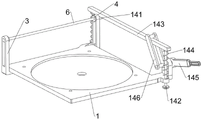
As shown in fig. 1 and 12, the lifting device 14 is further included, the lifting device 14 can push the slider 4 to slide downward, the lifting device 14 includes a contact rod 141, a second slide rod 142, a lifting plate 143, a seventh spring 144, a rotating plate 145 and a rotating frame 146, the contact rod 141 is welded on the slider 4 on the right side, the second slide rod 142 is connected to the right front portion of the placing plate 1 in a sliding manner, the lifting plate 143 is welded on the upper end of the second slide rod 142, the rear end of the lifting plate 143 is in contact with the contact rod 141, the seventh spring 144 is connected between the second slide rod 142 and the placing plate 1, the rotating plate 145 is connected to the right front portion of the placing plate 1 in a rotating manner, the rotating frame 146 is welded to the left portion of the rotating plate 145, and the lifting plate 143 passes through the rotating frame 146.
When the device is used, a worker pushes the rotating plate 145 to rotate upwards, the rotating frame 146 rotates downwards to extrude the lifting plate 143 to move downwards, the lifting plate 143 moves downwards to drive the second sliding rod 142 to slide downwards, the seventh spring 144 deforms, the lifting plate 143 moves downwards while extruding the contact rod 141, the contact rod 141 moves downwards to drive the sliding block 4 to slide downwards, and then the cutting knife 7 moves downwards, after cutting is completed, the worker loosens the rotating plate 145, under the reset effect of the seventh spring 144, the second sliding rod 142 drives the lifting plate 143 to move upwards, the lifting plate 143 moves upwards to not extrude the contact rod 141 any more, and then the cutting knife 7 moves upwards to reset, and therefore the cutting knife can be more convenient for the worker to control the downward movement of the cutting knife 7 to cut.
While the disclosure has been shown and described with reference to certain exemplary embodiments thereof, it will be understood by those skilled in the art that various changes in form and details may be made therein without departing from the spirit and scope of the disclosure as defined by the appended claims and their equivalents. Accordingly, the scope of the present disclosure should not be limited to the above-described embodiments, but should be defined not only by the appended claims, but also by equivalents thereof.
Claims (8)
1. The utility model provides a device is situated between to former piece of toughened glass, including placing board (1), support frame (2), carriage (3), slider (4), first spring (5), horizontal pole (6), cutting knife (7) and second spring (8), place board (1) downside bilateral symmetry and be connected with support frame (2), place board (1) left and right sides equal sliding connection of both parts have carriage (3), equal sliding connection has slider (4) on carriage (3), all be connected with between slider (4) and adjacent carriage (3) first spring (5), be connected with horizontal pole (6) between controlling two slider (4), sliding connection has cutting knife (7) on horizontal pole (6), be connected with second spring (8) between cutting knife (7) and horizontal pole (6), its characterized in that: the glass sheet placing device is characterized by further comprising a pressing mechanism (9) and a driving mechanism (10), the pressing mechanism (9) used for pressing the original toughened glass sheet is arranged on the placing plate (1), the driving mechanism (10) is arranged between the placing plate (1) and the sliding frame (3), and the driving mechanism (10) is used for driving the sliding frame (3) to slide back and forth.
2. The tempered glass precursor spacing device of claim 1, wherein: hold-down mechanism (9) are including first slide bar (91), third spring (92) and clamp plate (93), place board (1) left and right sides both parts front and back symmetry sliding connection have first slide bar (91), first slide bar (91) and place all be connected with third spring (92) between board (1), all be connected with clamp plate (93) between two first slide bar (91) upper portions on left two back right sides, clamp plate (93) downstream compresses tightly the former piece of toughened glass.
3. The tempered glass precursor spacing device of claim 2, wherein: the driving mechanism (10) comprises a driving motor (101), a screw rod (102) and a connecting rod (103), the front portion of the lower side of the placing plate (1) is connected with the driving motor (101), the output shaft of the driving motor (101) is connected with the screw rod (102), the connecting rod (103) is connected between the lower sides of the left sliding frame and the right sliding frame (3), the connecting rod (103) is in threaded connection with the screw rod (102), the screw rod (102) rotates to drive the connecting rod (103) to move back and forth, and then the sliding frame (3) is driven to slide back and forth.
4. The tempered glass precursor spacing device of claim 3, wherein: still including fixed establishment (11) that are used for fixed cutting knife (7) position, fixed establishment (11) are including connecting plate (110), fixed block (111), diaphragm (112), fourth spring (113) and stop block (114), be connected with connecting plate (110) between two sliders (4) about, even interval connection has one row of fixed block (111) on connecting plate (110), be connected with diaphragm (112) between one row of fixed block (111) rear side, both sides all are connected with fourth spring (113) about between diaphragm (112) and connecting plate (110), carriage (3) rear side lower part all is connected with blocks (114), diaphragm (112) move down and block (114) contact, and then by block (114) extrusion forward movement.
5. The tempered glass precursor spacing device of claim 4, wherein: the toughened glass original sheet rotating device is characterized by further comprising a rotating mechanism (12) used for driving a toughened glass original sheet to rotate, wherein the rotating mechanism (12) comprises a rotating block (121), a rotating disc (122), a gear (123), a sliding block (124), a fifth spring (125), a rack (126) and an L-shaped plate (127), the rotating block (121) is rotatably connected to the central position of the placing plate (1), the rotating disc (122) is connected to the upper portion of the rotating block (121), the gear (123) is connected to the lower portion of the rotating block (121) through an overrunning clutch, the sliding block (124) is slidably connected to the position, which is far to the left, of the placing plate (1), the fifth spring (125) is connected between the sliding block (124) and the placing plate (1), the rack (126) is connected to the right portion of the sliding block (124), the rack (126) is meshed with the gear (123), the L-shaped plate (127) is connected to the left portion of the sliding block (124), the connecting rod (103) moves forwards to be in contact with the L-shaped plate (127), and further extrudes the L-shaped plate (127) to move forwards.
6. The toughened glass original piece opening device as claimed in claim 5, wherein: still including being used for making pressing plate (93) lapse mechanism (13) of lapse that move down automatically, lapse mechanism (13) including mounting panel (131), briquetting (132) and sixth spring (133) down, carriage (3) sub-unit connection has mounting panel (131), all sliding type connection has briquetting (132) down on mounting panel (131), briquetting (132) are gone forward and are all contacted with adjacent pressing plate (93) down, and then promote pressing plate (93) lapse and compress tightly former piece of toughened glass, all be connected with sixth spring (133) between briquetting (132) and adjacent mounting panel (131) down.
7. The tempered glass original piece opening device as claimed in claim 6, wherein: the lifting mechanism (14) is used for pushing the sliding block (4) to slide downwards, the lifting mechanism (14) comprises a contact rod (141), a second sliding rod (142), a lifting plate (143), a seventh spring (144), a rotating plate (145) and a rotating frame (146), the contact rod (141) is connected to the sliding block (4) on the right side, the second sliding rod (142) is connected to the right front portion of the placing plate (1) in a sliding mode, the lifting plate (143) is connected to the upper end of the second sliding rod (142), the rear end of the lifting plate (143) is in contact with the contact rod (141), the seventh spring (144) is connected between the second sliding rod (142) and the placing plate (1), the rotating plate (145) is connected to the right front portion of the placing plate (1) in a rotating mode, the rotating frame (146) is connected to the left portion of the rotating plate (145), the lifting plate (143) penetrates through the rotating frame (146), and the rotating frame (146) rotates to extrude the lifting plate (143) to move downwards.
8. The toughened glass original piece opening device as claimed in claim 7, wherein: the pressing plate is characterized by further comprising a rubber pad (15), and the lower side of the pressing plate (93) is connected with the rubber pad (15).
Priority Applications (1)
| Application Number | Priority Date | Filing Date | Title |
|---|---|---|---|
| CN202210864600.7A CN115231814B (en) | 2022-07-21 | 2022-07-21 | Tempered glass original sheet medium opening device |
Applications Claiming Priority (1)
| Application Number | Priority Date | Filing Date | Title |
|---|---|---|---|
| CN202210864600.7A CN115231814B (en) | 2022-07-21 | 2022-07-21 | Tempered glass original sheet medium opening device |
Publications (2)
| Publication Number | Publication Date |
|---|---|
| CN115231814A true CN115231814A (en) | 2022-10-25 |
| CN115231814B CN115231814B (en) | 2024-02-06 |
Family
ID=83675707
Family Applications (1)
| Application Number | Title | Priority Date | Filing Date |
|---|---|---|---|
| CN202210864600.7A Active CN115231814B (en) | 2022-07-21 | 2022-07-21 | Tempered glass original sheet medium opening device |
Country Status (1)
| Country | Link |
|---|---|
| CN (1) | CN115231814B (en) |
Citations (11)
| Publication number | Priority date | Publication date | Assignee | Title |
|---|---|---|---|---|
| CN204434484U (en) * | 2015-01-15 | 2015-07-01 | 中江志诚钢化玻璃制品有限公司 | Can the sheet glass stationary installation of rapid adjustment cutting position |
| CN105060695A (en) * | 2015-08-21 | 2015-11-18 | 苏州凯锝微电子有限公司 | Glass cutting mechanism |
| CN105110616A (en) * | 2015-08-19 | 2015-12-02 | 苏州凯锝微电子有限公司 | Arc glass cutting device convenient for picking and placing glass |
| CN209890499U (en) * | 2019-06-03 | 2020-01-03 | 广州市环材玻璃有限公司 | Automatic cutting machine for glass plate products |
| CN112408764A (en) * | 2020-10-29 | 2021-02-26 | 郑自琴 | Beautiful glass quick cutting device for furniture |
| CN112429956A (en) * | 2020-11-24 | 2021-03-02 | 谭远茂 | Square scribing and cutting device for glass |
| CN113072296A (en) * | 2021-03-26 | 2021-07-06 | 刘剑锋 | Device for cutting round glass |
| CN214937019U (en) * | 2021-03-31 | 2021-11-30 | 常熟明阳玻璃制品有限公司 | Original sheet cutting device for production of toughened glass |
| CN114290080A (en) * | 2021-12-21 | 2022-04-08 | 邓丽琼 | Adjustable cutting equipment for plate processing |
| CN216337287U (en) * | 2021-12-15 | 2022-04-19 | 当阳市红安建材有限责任公司 | Former piece cutting device of glass |
| CN114378960A (en) * | 2021-12-27 | 2022-04-22 | 肖裔正 | Building material cutting device in building site |
-
2022
- 2022-07-21 CN CN202210864600.7A patent/CN115231814B/en active Active
Patent Citations (11)
| Publication number | Priority date | Publication date | Assignee | Title |
|---|---|---|---|---|
| CN204434484U (en) * | 2015-01-15 | 2015-07-01 | 中江志诚钢化玻璃制品有限公司 | Can the sheet glass stationary installation of rapid adjustment cutting position |
| CN105110616A (en) * | 2015-08-19 | 2015-12-02 | 苏州凯锝微电子有限公司 | Arc glass cutting device convenient for picking and placing glass |
| CN105060695A (en) * | 2015-08-21 | 2015-11-18 | 苏州凯锝微电子有限公司 | Glass cutting mechanism |
| CN209890499U (en) * | 2019-06-03 | 2020-01-03 | 广州市环材玻璃有限公司 | Automatic cutting machine for glass plate products |
| CN112408764A (en) * | 2020-10-29 | 2021-02-26 | 郑自琴 | Beautiful glass quick cutting device for furniture |
| CN112429956A (en) * | 2020-11-24 | 2021-03-02 | 谭远茂 | Square scribing and cutting device for glass |
| CN113072296A (en) * | 2021-03-26 | 2021-07-06 | 刘剑锋 | Device for cutting round glass |
| CN214937019U (en) * | 2021-03-31 | 2021-11-30 | 常熟明阳玻璃制品有限公司 | Original sheet cutting device for production of toughened glass |
| CN216337287U (en) * | 2021-12-15 | 2022-04-19 | 当阳市红安建材有限责任公司 | Former piece cutting device of glass |
| CN114290080A (en) * | 2021-12-21 | 2022-04-08 | 邓丽琼 | Adjustable cutting equipment for plate processing |
| CN114378960A (en) * | 2021-12-27 | 2022-04-22 | 肖裔正 | Building material cutting device in building site |
Also Published As
| Publication number | Publication date |
|---|---|
| CN115231814B (en) | 2024-02-06 |
Similar Documents
| Publication | Publication Date | Title |
|---|---|---|
| CN111374162B (en) | Automatic cake slicing equipment | |
| CN111331653B (en) | Lotus root starch processing is with section device | |
| CN111516049B (en) | Circular rubber pad intercepting device | |
| CN113558078B (en) | Automatic production machine for manufacturing round dough cover | |
| CN112547609A (en) | Flattening device for printing intelligent manufacturing | |
| CN113072296A (en) | Device for cutting round glass | |
| CN112810221A (en) | Ring-pull can batch flattening recovery device | |
| CN113319167B (en) | Metal building material bending equipment | |
| CN115231814A (en) | Original tempered glass sheet opening device | |
| CN113183195B (en) | Cutting device of square sponge | |
| CN112676397B (en) | Automatic change metal strip rotation molding equipment | |
| CN112935408A (en) | Industrial copper block slotting device | |
| CN113070592A (en) | Laser drilling equipment for sheet metal parts | |
| CN112759243A (en) | Industrial square glass cutting equipment | |
| CN114311058A (en) | Circuit board batch forming equipment for computer hardware research and development processing based on gear linkage | |
| CN112170960B (en) | Saw blade manufacturing device | |
| CN113618798B (en) | Dried bamboo shoot filament cutter with violently erect diversion function | |
| CN113967884A (en) | Pressing device for preventing deformation of plate during processing | |
| CN115723209B (en) | Quantitative cutting device for household fir ecological plate | |
| CN113290640A (en) | Plank slitting device for furniture production | |
| CN220462082U (en) | NTC resistance shearing mechanism | |
| CN216884137U (en) | Equidistant cutting device is used in production of glass intermediate coat | |
| CN115284348A (en) | Raw material slicing device for biological medicine | |
| CN220311437U (en) | Aluminum strip special-shaped profiling device | |
| CN217371435U (en) | Positioner is used in metal mesh processing |
Legal Events
| Date | Code | Title | Description |
|---|---|---|---|
| PB01 | Publication | ||
| PB01 | Publication | ||
| SE01 | Entry into force of request for substantive examination | ||
| SE01 | Entry into force of request for substantive examination | ||
| TA01 | Transfer of patent application right | ||
| TA01 | Transfer of patent application right |
Effective date of registration: 20240110 Address after: 411100 Phase II Workshop, No. 8 Xiangtan Avenue, Bantang Street, High tech Zone, Xiangtan City, Hunan Province Applicant after: Hunan Tancheng Glass Products Co.,Ltd. Address before: No. 519, Zhangyuan Avenue, Hengshui Town, Chongyi County, Ganzhou City, Jiangxi Province 341000 Applicant before: Chongyi Xinhao Glass Co.,Ltd. |
|
| GR01 | Patent grant | ||
| GR01 | Patent grant |