CN115214784A - Side wall assembly and car behind automobile body - Google Patents
Side wall assembly and car behind automobile body Download PDFInfo
- Publication number
- CN115214784A CN115214784A CN202210432064.3A CN202210432064A CN115214784A CN 115214784 A CN115214784 A CN 115214784A CN 202210432064 A CN202210432064 A CN 202210432064A CN 115214784 A CN115214784 A CN 115214784A
- Authority
- CN
- China
- Prior art keywords
- reinforcing
- assembly
- column
- vehicle body
- bracket
- Prior art date
- Legal status (The legal status is an assumption and is not a legal conclusion. Google has not performed a legal analysis and makes no representation as to the accuracy of the status listed.)
- Granted
Links
- 230000003014 reinforcing effect Effects 0.000 claims abstract description 321
- 230000002787 reinforcement Effects 0.000 claims description 32
- 238000010030 laminating Methods 0.000 claims description 4
- 230000005540 biological transmission Effects 0.000 abstract description 13
- 230000035945 sensitivity Effects 0.000 abstract description 9
- 230000029058 respiratory gaseous exchange Effects 0.000 abstract description 6
- 230000005284 excitation Effects 0.000 description 24
- 238000005452 bending Methods 0.000 description 6
- 238000005728 strengthening Methods 0.000 description 5
- 239000000872 buffer Substances 0.000 description 4
- 238000013016 damping Methods 0.000 description 3
- 230000001788 irregular Effects 0.000 description 3
- 230000007704 transition Effects 0.000 description 3
- 230000002238 attenuated effect Effects 0.000 description 2
- 230000009286 beneficial effect Effects 0.000 description 2
- 230000008878 coupling Effects 0.000 description 2
- 238000010168 coupling process Methods 0.000 description 2
- 238000005859 coupling reaction Methods 0.000 description 2
- 230000009467 reduction Effects 0.000 description 2
- 238000003466 welding Methods 0.000 description 2
- 230000006978 adaptation Effects 0.000 description 1
- 239000011324 bead Substances 0.000 description 1
- 239000003638 chemical reducing agent Substances 0.000 description 1
- 238000010276 construction Methods 0.000 description 1
- 230000004069 differentiation Effects 0.000 description 1
- 239000006185 dispersion Substances 0.000 description 1
- 230000000694 effects Effects 0.000 description 1
- 230000002349 favourable effect Effects 0.000 description 1
- 238000012986 modification Methods 0.000 description 1
- 230000004048 modification Effects 0.000 description 1
- 230000035939 shock Effects 0.000 description 1
- 239000003351 stiffener Substances 0.000 description 1
Images


Classifications
-
- B—PERFORMING OPERATIONS; TRANSPORTING
- B62—LAND VEHICLES FOR TRAVELLING OTHERWISE THAN ON RAILS
- B62D—MOTOR VEHICLES; TRAILERS
- B62D25/00—Superstructure or monocoque structure sub-units; Parts or details thereof not otherwise provided for
- B62D25/04—Door pillars ; windshield pillars
-
- B—PERFORMING OPERATIONS; TRANSPORTING
- B62—LAND VEHICLES FOR TRAVELLING OTHERWISE THAN ON RAILS
- B62D—MOTOR VEHICLES; TRAILERS
- B62D25/00—Superstructure or monocoque structure sub-units; Parts or details thereof not otherwise provided for
- B62D25/02—Side panels
-
- B—PERFORMING OPERATIONS; TRANSPORTING
- B62—LAND VEHICLES FOR TRAVELLING OTHERWISE THAN ON RAILS
- B62D—MOTOR VEHICLES; TRAILERS
- B62D25/00—Superstructure or monocoque structure sub-units; Parts or details thereof not otherwise provided for
- B62D25/08—Front or rear portions
- B62D25/16—Mud-guards or wings; Wheel cover panels
Landscapes
- Engineering & Computer Science (AREA)
- Chemical & Material Sciences (AREA)
- Combustion & Propulsion (AREA)
- Transportation (AREA)
- Mechanical Engineering (AREA)
- Body Structure For Vehicles (AREA)
Abstract
The invention provides a vehicle body rear side wall assembly and an automobile, belonging to the technical field of vehicles and comprising a left rear side wall structure and a right rear side wall structure; the left rear side wall structure comprises a left C column, a left D column, a left upper longitudinal beam, a left wheel casing assembly and a left reinforcing structure; the right rear side wall structure comprises a right side C column, a right side D column, a right side upper longitudinal beam, a right side wheel casing assembly and a right side reinforcing structure; the modal frequency of the left side reinforcing structure is not equal to the modal frequency of the right side reinforcing structure. The invention can increase the strength of the rear side wall assembly, avoid the similar breathing mode generated by the approach of the modal frequency of the side walls at the two sides of the vehicle body, reduce the vibration transmission sensitivity and provide a quiet and comfortable driving space for MPV vehicles.
Description
Technical Field
The invention belongs to the technical field of vehicles, and particularly relates to a vehicle body rear side wall assembly and an automobile.
Background
The rear side wall structure of the automobile body is connected with components such as a B column, a C column, a D column and the like, and plays an important role in bending resistance and torque resistance of the automobile body. Along with the increasing requirements of people on riding safety and comfort, the requirements on vibration reduction, noise reduction and impact resistance of the rear side wall of the automobile body are higher and higher.
Among the rear side wall structure of current MPV motorcycle type, the left rear side wall structure and the right rear side wall structure of automobile body both sides are the same, do not keep away the design frequently, can lead to automobile body both sides side wall modal frequency to be close and produce similar breathing mode, generate vibration noise and influence travelling comfort in the car.
Disclosure of Invention
The invention aims to provide a vehicle body rear side wall assembly and a vehicle, and aims to solve the problem that in the prior art, due to the fact that rear side wall structures on two sides of a vehicle body are the same, vibration noise is generated due to the fact that the modal frequencies of the side wall structures on the two sides of the vehicle body are close to each other.
In order to achieve the purpose, the invention adopts the technical scheme that: the utility model provides a vehicle body rear side wall assembly, which comprises a left rear side wall structure and a right rear side wall structure;
the left rear side wall structure comprises a left C column, a left D column, a left upper longitudinal beam and a left wheel cover assembly, wherein the left C column and the left D column are respectively connected with the left upper longitudinal beam and the left wheel cover assembly; a left side reinforcing structure is arranged in the left frame structure;
the right rear side wall structure comprises a right C column, a right D column, a right upper longitudinal beam and a right wheel cover assembly, wherein the right upper longitudinal beam and the right wheel cover assembly are respectively connected with the right C column and the right D column; a right side reinforcing structure is arranged in the right frame structure;
the modal frequency of the left side reinforcing structure is not equal to the modal frequency of the right side reinforcing structure.
In one possible implementation, the difference between the modal frequency of the left side reinforcing structure and the modal frequency of the right side reinforcing structure is greater than 4Hz.
In a possible implementation manner, the left reinforcing structure extends to the inside of the left frame structure in a scattered manner with the left wheel casing assembly as a center, and the branch ends include a first branch end connected with the left C-pillar, a second branch end connected with the left upper longitudinal beam, and a third branch end connected with the left D-pillar;
the right side reinforcing structure is connected with the right side C column and the right side D column along the front-back direction of the vehicle body, and the right side reinforcing structure is connected with the right side upper longitudinal beam and the right side wheel cover assembly along the up-down direction of the vehicle body.
In one possible implementation, the left side reinforcing structure includes:
the front end of the first reinforcing bracket is connected with the left C column, and the rear end of the first reinforcing bracket is connected with the left wheel casing assembly; the front end of the first reinforcing bracket is the first branch end;
the upper end of the second reinforcing bracket is connected with the left upper longitudinal beam, and the lower end of the second reinforcing bracket is connected with the left wheel casing assembly; the upper end of the second reinforcing bracket is one of the second branch ends; and
the front end of the third reinforcing bracket is connected with the left wheel casing assembly, the upper end of the third reinforcing bracket is connected with the left upper longitudinal beam, and the rear end of the third reinforcing bracket is connected with the left D-pillar; the upper end of the third reinforcing bracket is the other second branch end, and the rear end of the third reinforcing bracket is the third branch end.
In some embodiments, the first reinforcing brace is an upwardly curved arched beam-like structure; on the external direction in the automobile body, first enhancement support is located left side C post reaches the outside of left side wheel casing assembly, both ends have first connecting ear respectively around first enhancement support, and are two sets of first connecting ear respectively with the central point of left side C post lateral surface the central point of left side wheel casing assembly lateral surface is connected.
In some embodiments, the second reinforcing brace comprises:
the upper end of the upper supporting plate is connected with the left upper longitudinal beam, and the lower end of the upper supporting plate extends to the left wheel cover assembly; and
the lower connecting plate is attached to the outer side surface of the left wheel casing assembly and is connected with the left wheel casing assembly; the lower connecting plate comprises an extension part and a fitting part: the extension part is positioned on the outer side of the upper support plate in the inner and outer direction of the vehicle body, and the extension part is obliquely arranged towards the outer direction of the vehicle relative to the upper support plate; the upper end of the attaching part is integrally connected with the lower end of the extending part; the lower end of the attaching part is obliquely arranged towards the parking space and attached to the outer side surface of the left wheel cover assembly; wherein, the department of meeting of epitaxial portion with laminating portion with the lower extreme of going up the backup pad is connected.
In some embodiments, the third reinforcing brace comprises:
an external reinforcing bracket; the outer reinforcing bracket comprises an outer main body and second connecting lugs connected to the front end and the rear end of the outer main body, and the second connecting lugs protrude towards the inside of the vehicle; in the inside-outside direction of a vehicle body, the outer main body is positioned on the outer sides of the wheel cover assembly, the upper longitudinal beam and the D column; and
the inner reinforcing bracket is positioned on the inner side of the outer reinforcing bracket and is arranged at intervals with the outer reinforcing bracket in the inner and outer directions of the vehicle body; the inner reinforcing bracket comprises an inner main body and third connecting lugs connected to the front end and the rear end of the inner main body;
wherein, the front edges of the second connecting lug at the front end of the outer main body and the third connecting lug at the front end of the inner main body are respectively connected with the outer edge of the left wheel casing assembly; the rear edges of the second connecting lug at the rear end of the outer main body and the third connecting lug at the rear end of the inner main body are respectively connected with the outer edge of the left D column; in addition, a space is provided between the outer reinforcement bracket and the inner reinforcement bracket in the vehicle body inner-outer direction.
In one possible implementation, the right side reinforcing structure includes:
the front end of the reinforcing plate is connected with the right C column, the upper end of the reinforcing plate is connected with the right upper longitudinal beam, and the lower end of the reinforcing plate is connected with the right wheel casing assembly; and
and the front end of the reinforcing beam is connected with the reinforcing plate, and the rear end of the reinforcing beam is connected with the right D column.
In some embodiments, the reinforcing plate has, in a vehicle body inward-outward direction, an outward convex portion that protrudes outward and an inward concave portion that sinks inward; the convex part and the concave part are continuously distributed in the vertical direction of the vehicle body.
In some embodiments, the stiffener plate comprises:
the front end of the first reinforcing part is connected with the right C column, the upper end of the first reinforcing part is connected with the right upper longitudinal beam, and the lower end of the first reinforcing part is connected with the right wheel casing assembly; the first reinforcement portion includes a set of the male portions and a set of the female portions; in the vertical direction of the vehicle body, the convex parts and the concave parts of the first reinforcing part are distributed in sequence; and
the front end of the second reinforcing part is connected with the rear end of the first reinforcing part, the upper end of the second reinforcing part is connected with the right upper longitudinal beam, the lower end of the second reinforcing part is connected with the right wheel casing assembly, and the rear end of the second reinforcing part is connected with the right reinforcing beam; the second reinforcing part comprises two groups of the male parts and one group of the female parts; in the vertical direction of the vehicle body, one group of the convex parts, the concave part and the other group of the convex parts of the second reinforcing part are distributed in sequence;
wherein, in the vehicle body inside and outside direction, first rib, the second rib interval distributes.
In some embodiments, the convex portion above the second reinforcing portion and the convex portion of the first reinforcing portion each protrude outward from the right upper side member in the vehicle body inside-outside direction, and upper ends of the convex portion above the second reinforcing portion and the convex portion of the first reinforcing portion each have a first burring that extends obliquely upward in the vehicle body inside-outside direction and is connected to the right upper side member;
the front end of the first reinforcing part is provided with a second flanging, and the second flanging protrudes inwards in the inner and outer directions of the vehicle body and is connected with the right C column;
the rear end of the second reinforcing part is provided with a third flanging, and the third flanging protrudes inwards in the inner and outer directions of the vehicle body and is connected with the reinforcing beam;
and a fourth flanging is arranged between the first reinforcing part and the second reinforcing part.
In some embodiments, at least two groups of the reinforcing beams are arranged at intervals in the up-down direction of the vehicle body; the reinforcing beam is positioned on the outer side of the reinforcing plate and the right D-pillar in the inner and outer directions of the vehicle body, the front end and the rear end of the reinforcing beam are respectively provided with fourth connecting lugs protruding inwards, and the two groups of fourth connecting lugs are respectively connected with the rear end of the reinforcing plate and the right D-pillar.
The vehicle body rear side wall assembly provided by the invention has the beneficial effects that: compared with the prior art, the vehicle body rear side wall assembly is characterized in that a left side reinforcing structure is additionally arranged on a left rear side wall structure, a right side reinforcing structure is additionally arranged on a right rear side wall structure, the left rear side wall structure and the right rear side wall structure can form differentiation by differentiating the specific structures, specific shapes or specific size designs of the left side reinforcing structure and the right side reinforcing structure, so that the modal frequency of the left rear side wall structure is not equal to the modal frequency of the right rear side wall structure, the phenomenon that similar breathing modes are generated due to the fact that the modal frequencies of the side walls on the two sides of a vehicle body are close to each other is avoided, and the vibration noise at the rear side wall is reduced; in addition, the left side reinforcing structure and the right side reinforcing structure can also improve the structural strength of the rear side wall assembly, reduce the vibration transmission sensitivity and improve the impact resistance and the structural stability when the rear side wall assembly of the automobile body laterally collides.
The invention also provides an automobile which comprises the automobile body rear side wall assembly.
According to the automobile provided by the invention, the automobile body rear side wall assembly is adopted, so that the strength of the rear side wall assembly can be increased, the phenomenon that similar breathing modes are generated due to the fact that the side wall modal frequencies on the two sides of the automobile body are close to each other is avoided, the vibration noise sensitivity is reduced, the energy transmitted to a side wall structure by vibration excitation or collision excitation is attenuated, and a quiet and comfortable driving space is provided for MPV automobiles.
Drawings
In order to more clearly illustrate the technical solutions in the embodiments of the present invention, the drawings needed for the embodiments or the prior art descriptions will be briefly described below, and it is obvious that the drawings in the following description are only some embodiments of the present invention, and it is obvious for those skilled in the art to obtain other drawings without creative efforts.
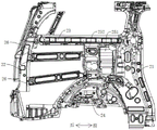
FIG. 1 is a schematic perspective view of a left rear side wall structure of a vehicle body rear side wall assembly according to an embodiment of the present invention;
FIG. 2 is a schematic front view of the structure of FIG. 1;
FIG. 3 is a rear view of the structure of FIG. 1;
FIG. 4 is a schematic perspective view of a first reinforcing brace used in an embodiment of the present invention;
FIG. 5 is a perspective view of a second reinforcing brace used in accordance with an embodiment of the present invention;
FIG. 6 is a perspective view of a third reinforcing brace utilized in embodiments of the present invention;
FIG. 7 is a perspective view of an outer reinforcing bracket of a third reinforcing bracket used in the embodiment of the present invention;
FIG. 8 is a schematic perspective view of a right rear side panel structure of a vehicle body rear side panel assembly according to an embodiment of the present invention;
FIG. 9 is a schematic front view of the structure of FIG. 1;
FIG. 10 is a rear view of the structure of FIG. 1;
FIG. 11 is a schematic perspective view of a reinforcing plate used in an embodiment of the present invention;
fig. 12 is a schematic perspective view of a reinforcing beam used in the embodiment of the present invention.
In the figure: 1. a left rear side wall structure; 11. a left C column; 12. a left D column; 13. a left upper stringer; 14. a left wheel cover assembly; 15. a first reinforcing bracket; 151. a first connecting lug; 16. a second reinforcing bracket; 161. an upper support plate; 1611. fifthly, flanging; 162. a lower connecting plate; 1621. an extension portion; 1622. a bonding section; 17. a third reinforcing bracket; 171. an external reinforcing bracket; 1711. a second engaging lug; 1712. an outer body; 1713. a first inclined edge; 1714. a middle edge; 1715. a second inclined edge; 172. an inner reinforcing bracket; 1721. a third engaging lug; 1722. an inner body; 18. a fourth reinforcing bracket; 2. a right rear side wall structure; 21. a right C column; 22. a right D column; 23. a right upper stringer; 24. a right wheel housing assembly; 25. a reinforcing plate; 251. a first reinforcing portion; 252. a second reinforcement portion; 253. an outer convex portion; 254. an inner concave portion; 255. a first flanging; 256. second flanging; 257. third flanging; 258. fourthly, flanging; 26. a reinforcing beam; 261. and a fourth engaging lug.
Detailed Description
In order to make the technical problems, technical solutions and advantageous effects to be solved by the present invention more clearly apparent, the present invention is further described in detail below with reference to the accompanying drawings and embodiments. It should be understood that the specific embodiments described herein are merely illustrative of the invention and are not intended to limit the invention.
It should be noted that, in the present embodiment, it is to be noted that the terms "front", "rear", "inside", "outside", "up", "down", and the like indicate the orientation or positional relationship based on the orientation of the vehicle itself, where the head of the vehicle represents "front", the tail of the vehicle represents "rear", the top of the vehicle represents "up", the bottom of the vehicle represents "down", "inside" side means a side facing the inside of the cab, and the outside side means a side facing the outside of the cab.
In addition, the vehicle body front-rear direction defined in the embodiments of the present invention refers to the front-rear direction of the advancing direction during the running of the automobile, the defined vehicle body inside-outside direction refers to the left-right direction of the advancing direction during the running of the automobile, and the defined vehicle body up-down direction refers to the up-down direction of the advancing direction during the running of the automobile.
Referring to fig. 1 to 3 and fig. 8 to 10 together, a vehicle body quarter assembly according to the present invention will now be described. The automobile body rear side wall assembly comprises a left rear side wall structure 1 and a right rear side wall structure 2.
The left rear side wall structure 1 comprises a left C column 11, a left D column 12, a left upper longitudinal beam 13 and a left wheel casing assembly 14, wherein the left upper longitudinal beam 13 and the left wheel casing assembly 14 are respectively connected with the left C column 11 and the left D column 12, and the left C column 11, the left D column 12, the left upper longitudinal beam 13 and the left wheel casing assembly 14 form a left frame structure; a left side reinforcing structure is arranged in the left frame structure;
the right rear side wall structure 2 comprises a right C column 21, a right D column 22, a right upper longitudinal beam 23 and a right wheel casing assembly 24, wherein the right upper longitudinal beam 23 and the right wheel casing assembly 24 are respectively connected with the right C column 21 and the right D column 22, and the right C column 21, the right D column 22, the right upper longitudinal beam 23 and the right wheel casing assembly 24 form a right frame structure; a right reinforcing structure is arranged in the right frame structure;
and the modal frequency of the left side reinforcing structure is not equal to the modal frequency of the right side reinforcing structure.
The modes are the natural vibration characteristics of the structural system, and the free vibration of the linear system is decoupled into N orthogonal single-degree-of-freedom vibration systems corresponding to the N modes of the system. Each mode has a specific natural frequency, damping ratio and mode shape. The modal frequency referred to in this embodiment refers to the first-order bending modal frequency of the vehicle body.
It should be noted that the modal frequency of the left side reinforcing structure is not equal to the modal frequency of the right side reinforcing structure, and may be caused by the difference between the specific shape, the specific structure, the specific size, and other factors of the left side reinforcing structure and the right side reinforcing structure.
Compared with the prior art, the vehicle body rear side wall assembly provided by the invention has the advantages that the left side reinforcing structure is additionally arranged on the left rear side wall structure 1, the right side reinforcing structure is additionally arranged on the right rear side wall structure 2, the modal frequency of the left side reinforcing structure is unequal to the modal frequency of the right side reinforcing structure by differentiating the specific structures or specific shapes or specific size designs of the left side reinforcing structure and the right side reinforcing structure, and further the modal frequency of the left rear side wall structure 1 is unequal to the modal frequency of the right rear side wall structure 2, so that the phenomenon that similar breathing modes are generated due to the approach of the modal frequencies of the side walls at the two sides of a vehicle body can be avoided, and the vibration noise at the rear side wall is reduced; in addition, the left side reinforcing structure and the right side reinforcing structure can also improve the structural strength of the rear side wall assembly, reduce the vibration transmission sensitivity and improve the impact resistance and the structural stability when the side wall structure of the automobile body is laterally collided.
In the present embodiment, the left side surrounding structure 1 refers to a driving side surrounding structure, and the right side surrounding structure 2 refers to a passenger side surrounding structure.
In some embodiments, the difference between the modal frequency of the left side reinforcing structure and the modal frequency of the right side reinforcing structure is greater than 4Hz.
When the vehicle system structure is designed, the frequency avoiding design is carried out on the first-order bending modal frequency of the vehicle body by more than 4Hz, so that the difference value between the modal frequency of the left side reinforcing structure and the modal frequency of the right side reinforcing structure is more than 4Hz, resonance can be avoided, and vibration excitation energy can be avoided being amplified.
In some embodiments, the left side reinforcing structure is provided with a plurality of branch ends distributed and extending towards the inside of the left frame structure by taking the left side wheel house assembly 14 as a center, and the plurality of branch ends comprise a first branch end connected with the left side C column 11, a second branch end connected with the left side upper longitudinal beam 13, and a third branch end connected with the left side D column 12.
The right side reinforcing structure is connected with the right side C column 21 and the right side D column 22 along the front-rear direction of the vehicle body, and is also connected with the right side upper longitudinal beam 23 and the right side wheel cover assembly 24 along the vertical direction of the vehicle body.
Wherein, the difference value between the modal frequency of the left rear side wall structure 1 and the modal frequency of the right rear side wall structure 2 is larger than 4Hz.
The left side additional strengthening uses left side wheel casing assembly 14 to extend a plurality of branch ends to left frame construction's inside dispersion as the center to utilize first branch end to be connected with left side C post 11, utilize the second branch end to be connected with left side upper longitudinal beam 13, utilize the third branch end to be connected with left side D post 12, promote left rear side wall structure 1's bulk strength, make vibration excitation accessible left side additional strengthening disperse to left side C post 11, left side upper longitudinal beam 13 and left side D post 12, thereby reduce vibration transfer sensitivity.
The left side reinforcing structure is additionally arranged in the left frame structure, so that the modal frequency of the left rear side wall structure 1 is about 90 Hz.
The right side reinforcing structure is connected with the right side C column 21 and the right side D column 22 along the front-rear direction of the vehicle body, and is also connected with the right side upper longitudinal beam 23 and the right side wheel cover assembly 24 along the up-down direction of the vehicle body, so that the overall strength of the right rear side wall structure 2 is improved, vibration excitation can be dispersed to the right side C column 21, the right side upper longitudinal beam 23 and the right side D column 22 through the right side reinforcing structure, and the vibration transmission sensitivity is reduced.
By additionally arranging the right side reinforcing structure in the right frame structure, the modal frequency of the right rear side wall structure 2 is about 79 Hz.
Because the difference value between the modal frequency of the left rear side wall structure 1 and the modal frequency of the right rear side wall structure 2 is more than 4Hz, the resonance can be avoided, and the vibration excitation energy can be avoided from being amplified.
In some embodiments, the left reinforcing structure may be as shown in fig. 1 to 3. Referring to fig. 1 to 3, the left side reinforcing structure includes a first reinforcing bracket 15, a second reinforcing bracket 16, and a third reinforcing bracket 17.
The front end of the first reinforcing bracket 15 is connected with the left C column 11, and the rear end is connected with the left wheel casing assembly 14; the upper end of the second reinforcing bracket 16 is connected with the left upper longitudinal beam 13, and the lower end is connected with the left wheel casing assembly 14; the front end of the third reinforcing bracket 17 is connected with the left wheel casing assembly 14, the upper end is connected with the left upper longitudinal beam 13, and the rear end is connected with the left D-pillar 12.
The first reinforcing bracket 15, the second reinforcing bracket 16 and the third reinforcing bracket 17 are arranged at intervals in the front-rear direction of the vehicle body, one end of each of the first reinforcing bracket 15, the second reinforcing bracket 16 and the third reinforcing bracket 17 is connected with the left wheel cover assembly 14, the front end of the first reinforcing bracket 15 is the first branch end, the upper end of the second reinforcing bracket 16 is one of the second branch ends, the upper end of the third reinforcing bracket 17 is the other second branch end, and the rear end of the third reinforcing bracket 17 is the third branch end. That is, the first reinforcing brace 15, the second reinforcing brace 16, and the third reinforcing brace 17 are formed in a dispersed form that is dispersed and extends toward the inside of the left frame structure centering on the left wheel house assembly 14.
According to the left rear side wall structure 1 provided by the invention, the first reinforcing support 15, the second reinforcing support 16 and the third reinforcing support 17 are arranged in the left frame structure, the first reinforcing support 15 is connected with the left frame structure in the front-back direction of the vehicle body, the second reinforcing support 16 is connected with the left frame structure in the front-back direction of the vehicle body, and the third reinforcing support 17 is connected with the left frame structure in the front-back direction of the vehicle body and the front-back direction of the vehicle body, so that the strength of the left frame structure is improved, three groups of force transmission channels can be formed in the left frame structure, and the force transmission channels can transmit, buffer and absorb vibration excitation and collision excitation, thereby being beneficial to damping vibration, reducing vibration transmission sensitivity, reducing noise in the vehicle, and improving the impact resistance and the structural stability of the left rear side wall structure 1 during side collision.
In some embodiments, the first reinforcing brackets 15 may be configured as shown in fig. 4. Referring to fig. 4, the first reinforcing brackets 15 are of an upwardly curved arched beam-like structure; in the vehicle body inside-outside direction, the first reinforcing bracket 15 is located outside the left C-pillar 11 and the left wheel house assembly 14, the front end and the rear end of the first reinforcing bracket 15 are respectively provided with a first connecting lug 151, and the two groups of first connecting lugs 151 are respectively connected with the central part of the outer side surface of the left C-pillar 11 and the central part of the outer side surface of the left wheel house assembly 14.
The first reinforcing bracket 15 with the arch structure has the characteristics of high bending resistance and high impact strength, and can improve the strength between the left C column 11 and the left wheel cover assembly 14; in addition, the first reinforcing bracket 15 is located on the outer side of the left C-pillar 11 and the left wheel cover assembly 14, and when a side collision occurs to the vehicle, the first reinforcing bracket 15 absorbs and buffers collision energy first, so as to reduce collision excitation received by the left C-pillar 11 and the left wheel cover assembly 14. The first connecting lug 151 extends obliquely inward for fixed connection with the left C-pillar 11 and the left wheel cover assembly 14.
In addition to the first reinforcing bracket 15, a fourth reinforcing bracket 18 is connected between the left C-pillar 11 and the left wheel house assembly 14. The fourth reinforcing bracket 18 is positioned inside the first reinforcing bracket 15 in the vehicle body inside-outside direction, and is disposed at a distance from the first reinforcing bracket 15; the front end of the fourth reinforcing bracket 18 is connected to the inner side surface of the left C-pillar 11 facing the left frame structure, and the rear end of the fourth reinforcing bracket 18 is connected to the top surface of the left wheel house assembly 14, as shown in fig. 1.
The fourth reinforcing bracket 18 is located at the connecting corner of the left C-pillar 11 and the left wheel cover assembly 14, as shown in fig. 1. The fourth reinforcing bracket 18 serves to further enhance the overall strength of the left frame structure.
In some embodiments, the second reinforcing brackets 16 may be configured as shown in FIG. 5. Referring to fig. 5, the second reinforcing bracket 16 includes an upper support plate 161 and a lower connection plate 162. The upper end of the upper support plate 161 is connected with the left upper longitudinal beam 13, and the lower end extends to the left wheel cover assembly 14; the lower connecting plate 162 is attached to the outer side surface of the left wheel house assembly 14, connected to the left wheel house assembly 14, and fixedly connected to the lower end of the upper support plate 161.
The upper support plate 161 serves to increase the strength between the left wheel house assembly 14 and the left upper side member 13, and also forms a force transmission path in the up-down direction of the vehicle body. The vibration excitation transmitted from the tire and the rear motor reducer is decomposed and dispersed upward to the left upper side member 13, the left C-pillar 11 and the left D-pillar 12 through the upper support plate 161, thereby reducing the vibration transmission sensitivity.
The lower connecting plate 162 is attached to the outer side surface of the left wheel cover assembly 14, so that the strength of the left wheel cover assembly 14 is increased, and the stability of the upper supporting plate 161 is ensured.
Preferably, the upper support plate 161 is located outside the left upper side member 13 in the vehicle body inside-outside direction, and a fifth burring 1611 protruding toward the vehicle interior is provided around the upper support plate 161, as shown in fig. 5.
Since the left upper longitudinal beam 13 has an elongated beam structure and the upper support plate 161 has an irregular plate or block structure, the strength and stability of the upper support plate 161 are due to the left upper longitudinal beam 13. The upper support plate 161 protrudes outward from the left upper longitudinal beam 13, so that when the vehicle collides, the upper support plate 161 can absorb the collision energy and deform before the left upper longitudinal beam 13, thereby protecting the left upper longitudinal beam 13 from being damaged.
Preferably, lower web 162 includes an outer extension 1621 and a conforming portion 1622, as shown in fig. 5; the extending portion 1621 is located outside the upper support plate 161 in the vehicle body inside-outside direction, and the extending portion 1621 is disposed obliquely toward the vehicle outside direction with respect to the upper support plate 161; the upper end of the attachment portion 1622 is integrally connected to the lower end of the extension portion 1621; the lower end of the attaching portion 1622 is disposed obliquely toward the vehicle exterior direction and attached to the outer side surface of the left wheel house assembly 14; wherein, the junction of the extension part 1621 and the fitting part 1622 is connected with the lower end of the upper support plate 161.
Specifically, the extension 1621 extends from top to bottom, then extends obliquely downward from outside to inside, and then is attached to and fixedly connected with the upper support plate 161 after being bent. The extending portion 1621 has a bent plate-like structure as a whole. The extension 1621 may also be connected to other components. The fitting portion 1622 is adapted to the shape and structure of the outer side surface of the left wheel cover assembly 14. In this embodiment, the attaching portion 1622 extends from top to bottom, bends and then extends from inside to outside in an inclined manner, and bends and then extends from top to bottom. The whole bonding portion 1622 has a bent plate-like structure.
The extending portion 1621 is a bent plate-shaped structure, so that it can bear external impact force, and the whole lower connecting plate 162 has the characteristics of large bending resistance and impact strength, and can increase the strength of the lower connecting plate 162. Laminating portion 1622 laminating is fixed on left side wheel casing assembly 14, and with the shape structure looks adaptation of left side wheel casing assembly 14 lateral surface, can promote the fixed strength of connecting plate 162 down.
In some embodiments, the third reinforcing brackets 17 may be configured as shown in fig. 6. Referring to fig. 6, the third reinforcing bracket 17 includes an outer reinforcing bracket 171 and an inner reinforcing bracket 172. The front end of the outer reinforcing bracket 171 is connected with the left wheel casing assembly 14, the upper end of the outer reinforcing bracket is connected with the left upper longitudinal beam 13, and the rear end of the outer reinforcing bracket is connected with the left D-pillar 12; in the vehicle body inside-outside direction, the inner reinforcing bracket 172 is located inside the outer reinforcing bracket 171 and is spaced apart from the outer reinforcing bracket 171; the front end and the rear end of the inner reinforcing bracket 172 are respectively connected with the left wheel casing assembly 14 and the left D-pillar 12.
Preferably, the outer reinforcement bracket 171 includes an outer body 1712, and second coupling lugs 1711 coupled to front and rear ends of the outer body 1712, the second coupling lugs 1711 protruding inward; the outer body 1712 is located outside the left wheel house assembly 14, the left upper side member 13, and the left D-pillar 12 in the vehicle body inward-outward direction; second engaging lug 1711 projects inward; the inner reinforcing bracket 172 includes an inner body 1722, and third engaging lugs 1721 connected to front and rear ends of the inner body 1722.
Wherein, the front edge of the second engaging lug 1711 at the front end of the outer body 1712 and the front edge of the third engaging lug 1721 at the front end of the inner body 1722 are respectively connected with the outer edge of the left wheel cover assembly 14, and the third engaging lug 1721 is located right below the second engaging lug 1711; the rear edge of the second engaging lug 1711 at the rear end of the outer body 1712 and the rear edge of the third engaging lug 1721 at the rear end of the inner body 1722 are respectively connected with the outer edge of the left D-pillar 12, and the third engaging lug 1721 is positioned right below the second engaging lug 1711; in addition, the upper end of the outer main body 1712 is also connected with a second connecting lug 1711, and the upper edge of the second connecting lug 1711 is connected with the edge of the left upper longitudinal beam 13; in the vehicle body inner-outer direction, a space is provided between the outer reinforcement bracket 171 and the inner reinforcement bracket 172.
Through set up three groups of second engaging lug 1711 on strengthening the support 171 outward, set up two sets of third engaging lugs 1721 on strengthening the support 172 including, and make interior enhancement support 172 be located the positive inboard rear of strengthening the support 171 outward, can make interior enhancement support 172, outer reinforcement support 171 and left side upper longitudinal beam 13 and left side wheel casing assembly 14 enclose into closed, this space can absorb external vibration and collision excitation, thereby be favorable to the damping vibration, reduce the interior noise of car, and impact resistance and structural stability when improving the side impact.
In addition, the second engaging lug 1711 protrudes inward toward the vehicle interior, so that the outer reinforcement bracket 171 integrally forms a similar arch structure with a middle portion protruding outward and an edge portion protruding inward, when the vehicle collides, the outer main body 1712 can firstly absorb the collision energy and deform, and then protect the left upper longitudinal beam 13 and the left D-pillar 12, so as to reduce the collision excitation on the left upper longitudinal beam 13, the left wheel cover assembly 14 and the left D-pillar 12.
In order to further enhance the strength of the outer reinforcing bracket 171, it is preferable that the outer body 1712 has a polygonal plate-shaped structure. Specifically, as shown in fig. 7, the upper end edge of the outer body 1712 includes, in order from front to back, a first inclined edge 1713, an intermediate edge 1714, and a second inclined edge 1715, the first inclined edge 1713 being inclined from front to back, and the second inclined edge 1715 being inclined from front to back; the middle edge 1714 is attached to the second attachment ear 1711. The lower end edge, the front end edge and the rear end edge of the outer body 1712 are all straight edges or arc edges.
Specifically, the front end edge of the outer body 1712 is connected to the second connecting lug 1711 at the front end, and the rear end edge of the outer body 1712 is connected to the second connecting lug 1711 at the rear end; the first inclined edge 1713 smoothly transitions to the second engaging lug 1711 at the front end and the second engaging lug 1711 at the upper end, and the second inclined edge 1715 smoothly transitions to the second engaging lug 1711 at the upper end and the second engaging lug 1711 at the rear end.
The outer body 1712 may resemble a triangular plate-like structure, may facilitate a transitional connection between the three sets of second engaging lugs 1711, and may provide strength to the overall arcuate structure of the outer reinforcement bracket 171.
Of course, the inner reinforcing bracket 172 may be designed to have a middle portion protruding outward and an edge portion protruding inward in a similar arch structure, that is, the third engaging lug 1721 protrudes inward or outward relative to the inner reinforcing bracket 172; also, the inner body 1722 may be configured to resemble a triangular plate-like structure to provide strength to the overall arcuate structure of the inner stiffening cradle 172.
In some embodiments, the second reinforcing bracket 16 and the third reinforcing bracket 17 are both provided with collapsing holes, and the collapsing holes can reduce the weight of the second reinforcing bracket 16 and the third reinforcing bracket 17, and can also absorb external excitation, absorb collision energy, and reduce vibration noise. Specifically, the outer reinforcing brackets 171 and the inner reinforcing brackets 172 are provided with collapsing holes; the upper support plate 161 and the lower connecting plate 162 are also provided with collapsing holes.
In some embodiments, the right reinforcing structure may be as shown in fig. 8, 9 and 10. Referring to fig. 8, 9 and 10, the right quarter structure 2 further includes a reinforcement plate 25 and a reinforcement beam 26 located within the right frame structure.
The front end of the reinforcing plate 25 is connected with the right C-pillar 21, the upper end of the reinforcing plate 25 is connected with the right upper longitudinal beam 23, and the lower end of the reinforcing plate 25 is connected with the right wheel cover assembly 24; the front end of the reinforcing beam 26 is connected to the reinforcing plate 25, and the rear end of the reinforcing beam 26 is connected to the right D-pillar 22.
Specifically, the right C-pillar 21 includes a C-pillar inner panel and a C-pillar outer panel, the right D-pillar 22 includes a D-pillar inner panel and a D-pillar outer panel, and the right wheel cover assembly 24 includes a wheel cover inner panel and a wheel cover outer panel. The front end of the reinforcing plate 25 is fixed between the C-pillar inner plate and the C-pillar outer plate, and the lower end of the reinforcing plate 25 is fixed on the top surface of the wheel cover outer plate; the rear end of the reinforcing beam 26 is fixed to the D-pillar outer panel.
According to the right rear side wall structure 2 provided by the invention, the reinforcing plate 25 and the reinforcing beam 26 are arranged in the right frame structure, the reinforcing plate 25 is connected with the right frame structure in the up-down direction of the vehicle body, and the reinforcing plate 25 and the reinforcing beam 26 are combined to be connected with the right frame structure in the front-back direction of the vehicle body, so that the strength of the right frame structure is improved, force transmission channels in the up-down direction and the front-back direction of the vehicle body can be formed in the right frame structure, vibration excitation and collision excitation can be transmitted, buffered and absorbed by the force transmission channels, vibration attenuation is facilitated, noise in the vehicle is reduced, and the impact resistance and the structural stability of the right rear side wall structure 2 during side collision can be improved.
In some embodiments, the reinforcing plate 25 may have a structure as shown in fig. 11. Referring to fig. 11, in the vehicle body inside-outside direction, the reinforcement plate 25 has an outwardly convex portion 253 that protrudes outward and an inwardly concave inner portion 254; the convex portion 253 and the concave portion 254 are continuously distributed in the vehicle body up-down direction.
In addition, the convex portion 253 and the concave portion 254 are defined such that, with respect to the vehicle body inward-outward direction, with respect to one reference surface (the reference surface perpendicular to the vehicle body inward-outward direction) of the reinforcing plate 25, the convex portion 253 protrudes outward of the vehicle with respect to the reference surface, and the concave portion 254 is recessed inward of the vehicle with respect to the reference surface.
The reinforcing plate 25 has an outer convex portion 253 and an inner concave portion 254, and the outer convex portion 253 and the inner concave portion 254 are continuously distributed in the vehicle body up-down direction, that is, the reinforcing plate 25 has an S-shaped structure. When the vehicle is in collision, the inner concave part 254 and the outer convex part 253 can respectively absorb collision energy to improve the impact-resistant and good structural stability of the right frame structure; in addition, the convex portions 253 and the concave portions 254 are continuously distributed in the vertical direction of the vehicle body, and compared with a flat plate structure, on the one hand, the strength of the reinforcing plate 25 can be improved, and on the other hand, the force transmission path of the reinforcing plate 25 in the vertical direction of the vehicle body and in the vertical direction of the vehicle body can be increased, so that the reinforcing plate 25 can buffer and absorb external excitation in the vertical direction of the vehicle body and in the vertical direction of the vehicle body, and vibration noise can be reduced.
The reinforcing plate 25 can absorb and absorb external excitation in the vehicle body front-rear direction in addition to the external excitation in the vehicle body up-down direction and the vehicle body inside-outside direction, and in order to achieve the above object, on the basis of the above embodiment, the reinforcing plate 25 may also adopt a structure as shown in fig. 11, see fig. 11, and the reinforcing plate 25 includes a first reinforcing portion 251 and a second reinforcing portion 252; the front end of the first reinforcing part 251 is connected with the right C column 21, the upper end is connected with the right upper longitudinal beam 23, and the lower end is connected with the right wheel casing assembly 24; the second reinforcing part 252 is positioned behind the first reinforcing part 251, the front end of the second reinforcing part 252 is connected with the rear end of the first reinforcing part 251, the upper end of the second reinforcing part is connected with the right upper longitudinal beam 23, the lower end of the second reinforcing part is connected with the right wheel cover assembly 24, and the rear end of the second reinforcing part 252 is connected with the reinforcing beam 26; the first reinforcing portion 251 and the second reinforcing portion 252 are spaced apart from each other in the vehicle body inward-outward direction.
In the vehicle body inside-outside direction, the first reinforcing portion 251 and the second reinforcing portion 252 are spaced apart, that is, on a reference plane perpendicular to the vehicle body inside-outside direction, the first reinforcing portion 251 is disposed to project toward the outside of the vehicle (or project toward the inside of the vehicle) with respect to the reference plane, and the second reinforcing portion 252 is disposed to project toward the inside of the vehicle (or project toward the outside of the vehicle) with respect to the reference plane.
The first reinforcing portion 251 and the second reinforcing portion 252 are distributed along the front-rear direction of the vehicle body and spaced along the inner-outer direction of the vehicle body, so that the strength of the reinforcing plate 25 can be improved, the force transmission path of the reinforcing plate 25 in the front-rear direction of the vehicle body can be increased, the reinforcing plate 25 can buffer and absorb external excitation in the front-rear direction of the vehicle body, and vibration noise is reduced.
Preferably, the second reinforcement portion 252 in the present embodiment includes two sets of male protrusions 253 and one set of female protrusions 254; in the vertical direction of the vehicle body, one set of convex-outward portions 253, one set of concave-inward portions 254, and the other set of convex-outward portions 253 of the second reinforcing portion 252 are continuously distributed in this order; the first reinforcement part 251 includes a set of male parts 253 and a set of female parts 254; the convex portion 253 and the concave portion 254 of the first reinforcing portion 251 are continuously distributed in this order in the vehicle body up-down direction.
The number of the convex portions 253 of the second reinforcing portion 252 is larger than the number of the convex portions 253 of the first reinforcing portion 251, so that the first reinforcing portion 251 and the second reinforcing portion 252 naturally form a spaced structure in the vehicle body inner-outer direction. In addition, the irregular structure formed by the first reinforcing part 251 and the second reinforcing part 252 can improve the collision and crush capability and the shock absorbing capability of the whole reinforcing plate 25.
It should be noted that the reinforcing plate 25 in this embodiment is an integrally formed structure, and the first reinforcing portion 251 and the second reinforcing portion 252, and the male portion 253 and the female portion 254 are connected in a smooth transition manner.
In some embodiments, the reinforcing plate 25 may be configured as shown in fig. 8 and 11. Referring to fig. 8 and 11, the convex portion 253 above the second reinforcing portion 252 and the convex portion 253 of the first reinforcing portion 251 each protrude outward from the right upper side member 23 in the vehicle body inside-outside direction, and the upper ends of the convex portion 253 above the second reinforcing portion 252 and the convex portion 253 of the first reinforcing portion 251 each have a first burring 255, and the first burring 255 extends obliquely upward in the vehicle body inside-outside direction and is connected to the right upper side member 23. Preferably, the first flange 255 is fixedly welded between the upper side member inner panel and the upper side member outer panel of the right upper side member 23.
Since the right upper longitudinal beam 23 has an elongated beam structure and the reinforcing plate 25 has an irregular plate or block structure, the strength and stability of the reinforcing plate 25 are due to the right upper longitudinal beam 23. And the two outer convex portions 253 are protruded outwards from the right upper longitudinal beam 23, so that when the vehicle is collided, the reinforcing plate 25 can absorb collision energy and deform before the right upper longitudinal beam 23, and the right upper longitudinal beam 23 can be protected from being damaged.
In some embodiments, the reinforcing plate 25 may also adopt a structure as shown in fig. 8 and 11, and referring to fig. 8 and 11, the front end of the first reinforcing portion 251 has a second flange 256, and in the vehicle body inside and outside direction, the second flange 256 protrudes inwards and is connected with the right C-pillar 21; the rear end of the second reinforcing portion 252 has a third flange 257, and the third flange 257 projects inward in the vehicle body inward-outward direction and is connected to the reinforcing beam 26; a fourth bead 258 is provided between the first reinforcement portion 251 and the second reinforcement portion 252 in the vehicle body inward-outward direction.
As shown in fig. 11, the whole reinforcing plate 25 has flanges around it, and the flanges are used to weld and fix the right frame structure. In addition, the second flange 256 and the third flange 257 are provided to increase the force transfer area of the reinforcing plate 25 and facilitate the welding operation. The fourth flange 258 is provided to form a spaced-apart arrangement of the first and second reinforcements 251 and 252.
Specifically, the second flange 256 is welded between the C-pillar outer panel and the C-pillar inner panel. The lower end of the second reinforcement portion 252 also has a flange for welding to the top of the wheel cover outer plate.
In some embodiments, the reinforcing beam 26 may be configured as shown in fig. 8, 9, and 10. Referring to fig. 8, 9, and 10, at least two sets of reinforcement beams 26 are provided at intervals in the vehicle body vertical direction. In the up-down direction of the vehicle body, the plurality of groups of reinforcing beams 26 and the right frame structure form a ladder-shaped structure, and the overall strength of the right frame structure is improved by utilizing the characteristics that the ladder-shaped structure has a plurality of closed spaces and is high in strength.
In some embodiments, the reinforcing beam 26 is located outside the reinforcing plate 25 and the right D-pillar 22 in the vehicle body inward and outward direction, the front and rear ends of the reinforcing beam 26 are respectively provided with fourth engaging lugs 261 protruding inward, and as shown in fig. 12, two sets of the fourth engaging lugs 261 are respectively connected to the rear end of the reinforcing plate 25 and the right D-pillar 22.
Preferably, the fourth engaging lug 261 is provided by extending the end of the reinforcing beam 26 obliquely to the periphery of the reinforcing beam 26, so that the reinforcing beam 26 has a beam structure with two ends bent inward and a middle extending in the front-rear direction of the vehicle body as a whole.
Because the fourth lugs 261 protrude inwards, and a similar arch structure is formed between the two groups of fourth lugs 261 and the reinforcing beam 26, on one hand, the strength of the reinforcing beam 26 can be increased, and the reinforcing beam has the characteristics of high bending resistance and high impact strength; on the other hand, the body of the reinforcement beam 26 may be positioned outside the reinforcement plate 25 and the right D-pillar 22, and the reinforcement beam 26 may absorb the collision excitation prior to the right D-pillar 22 to protect the right D-pillar 22 and reduce the collision excitation received by the right D-pillar 22.
Preferably, the reinforcing beam 26 and the reinforcing plate 25 are both provided with a collapsing hole, as shown in fig. 11 and 12, the collapsing hole can reduce the weight of the reinforcing beam 26 and the reinforcing plate 25, and can also absorb external excitation, absorb collision energy, and reduce vibration noise.
Based on the same inventive concept, the embodiment of the invention also provides an automobile, which comprises the automobile body rear side wall assembly.
According to the automobile provided by the invention, the automobile body rear side wall assembly is adopted, so that the strength of the rear side wall assembly can be increased, the phenomenon that similar breathing modes are generated due to the fact that the side wall modal frequencies on the two sides of the automobile body are close is avoided, the sensitivity of vibration noise is reduced, the energy transmitted to a side wall structure by vibration excitation or collision excitation is attenuated, and a quiet and comfortable driving space is provided for MPV automobile models.
The above description is only for the purpose of illustrating the preferred embodiments of the present invention and is not to be construed as limiting the invention, and any modifications, equivalents and improvements made within the spirit and principle of the present invention are intended to be included within the scope of the present invention.
Claims (12)
1. A vehicle body rear side wall assembly is characterized by comprising a left rear side wall structure and a right rear side wall structure;
the left rear side wall structure comprises a left C column, a left D column, a left upper longitudinal beam and a left wheel casing assembly, wherein the left C column and the left D column are respectively connected with the left upper longitudinal beam and the left wheel casing assembly; a left side reinforcing structure is arranged in the left frame structure;
the right rear side wall structure comprises a right C column, a right D column, a right upper longitudinal beam and a right wheel cover assembly, wherein the right upper longitudinal beam and the right wheel cover assembly are respectively connected with the right C column and the right D column; a right side reinforcing structure is arranged in the right frame structure;
the modal frequency of the left side reinforcing structure is not equal to the modal frequency of the right side reinforcing structure.
2. The body quarter assembly of claim 1 wherein the difference between the modal frequency of the left side reinforcement structure and the modal frequency of the right side reinforcement structure is greater than 4Hz.
3. The body side quarter assembly of claim 2 wherein said left side reinforcement structure extends divergently inwardly of said left frame structure centered on said left wheel house assembly, a plurality of branch ends including a first branch end connected to said left C-pillar, a second branch end connected to said left upper side rail, and a third branch end connected to said left D-pillar;
the right side reinforcing structure is connected with the right side C column and the right side D column along the front-back direction of the vehicle body, and the right side reinforcing structure is connected with the right side upper longitudinal beam and the right side wheel cover assembly along the up-down direction of the vehicle body.
4. The body quarter assembly of claim 3 wherein said left side reinforcement structure comprises:
the front end of the first reinforcing bracket is connected with the left C column, and the rear end of the first reinforcing bracket is connected with the left wheel casing assembly; the front end of the first reinforcing bracket is the first branch end;
the upper end of the second reinforcing bracket is connected with the left upper longitudinal beam, and the lower end of the second reinforcing bracket is connected with the left wheel casing assembly; the upper end of the second reinforcing bracket is one of the second branch ends; and
the front end of the third reinforcing bracket is connected with the left wheel casing assembly, the upper end of the third reinforcing bracket is connected with the left upper longitudinal beam, and the rear end of the third reinforcing bracket is connected with the left D-pillar; the upper end of the third reinforcing bracket is the other second branch end, and the rear end of the third reinforcing bracket is the third branch end.
5. The body quarter assembly of claim 4 wherein said first reinforcement bracket is an upwardly curved arched beam-like structure; on the outside direction in the automobile body, first enhancement support is located the left side C post reaches the outside of left side wheel casing assembly, both ends have first connecting ear, two sets of respectively around the first enhancement support first connecting ear respectively with the central point of left side C post lateral surface the central point of left side wheel casing assembly lateral surface is connected.
6. The body quarter subassembly of claim 4 wherein said second reinforcing bracket comprises:
the upper end of the upper supporting plate is connected with the left upper longitudinal beam, and the lower end of the upper supporting plate extends to the left wheel cover assembly; and
the lower connecting plate is attached to the outer side surface of the left wheel casing assembly and is connected with the left wheel casing assembly; the lower connecting plate comprises an extension part and a fitting part: the extension part is positioned on the outer side of the upper support plate in the inner and outer directions of the vehicle body, and the extension part is obliquely arranged towards the outer direction of the vehicle relative to the upper support plate; the upper end of the attaching part is integrally connected with the lower end of the extending part; the lower end of the attaching part is obliquely arranged towards the outside of the vehicle and attached to the outer side surface of the left wheel cover assembly; wherein, the department of meeting of epitaxial portion with laminating portion with the lower extreme of going up the backup pad is connected.
7. The body quarter subassembly of claim 4 wherein said third reinforcing bracket comprises:
an external reinforcing bracket; the outer reinforcing bracket comprises an outer main body and second connecting lugs connected to the front end and the rear end of the outer main body, and the second connecting lugs protrude towards the inside of the vehicle; in the inner and outer direction of the vehicle body, the outer main body is positioned on the outer sides of the wheel cover assembly, the upper longitudinal beam and the D column; and
the inner reinforcing bracket is positioned on the inner side of the outer reinforcing bracket and is arranged at intervals with the outer reinforcing bracket in the inner and outer directions of the vehicle body; the inner reinforcing bracket comprises an inner main body and third connecting lugs connected to the front end and the rear end of the inner main body;
wherein, the front edges of the second connecting lug at the front end of the outer main body and the third connecting lug at the front end of the inner main body are respectively connected with the outer edge of the left wheel casing assembly; the rear edges of the second connecting lug at the rear end of the outer main body and the third connecting lug at the rear end of the inner main body are respectively connected with the outer edge of the left D column; in addition, a space is provided between the outer reinforcement bracket and the inner reinforcement bracket in the vehicle body inner-outer direction.
8. The body quarter assembly of any of claims 1 to 7, wherein said right side reinforcement structure comprises:
the front end of the reinforcing plate is connected with the right C column, the upper end of the reinforcing plate is connected with the right upper longitudinal beam, and the lower end of the reinforcing plate is connected with the right wheel casing assembly; and
and the front end of the reinforcing beam is connected with the reinforcing plate, and the rear end of the reinforcing beam is connected with the right D column.
9. The body quarter assembly as claimed in claim 8, wherein said gusset has an outwardly convex portion and an inwardly concave portion in the medial-lateral direction of the body; the convex part and the concave part are continuously distributed in the vertical direction of the vehicle body.
10. The body quarter panel assembly of claim 9 wherein said gusset includes:
the front end of the first reinforcing part is connected with the right C column, the upper end of the first reinforcing part is connected with the right upper longitudinal beam, and the lower end of the first reinforcing part is connected with the right wheel casing assembly; the first reinforcement portion includes a set of the male portions and a set of the female portions; in the vertical direction of the vehicle body, the convex parts and the concave parts of the first reinforcing part are distributed in sequence; and
the front end of the second reinforcing part is connected with the rear end of the first reinforcing part, the upper end of the second reinforcing part is connected with the right upper longitudinal beam, the lower end of the second reinforcing part is connected with the right wheel casing assembly, and the rear end of the second reinforcing part is connected with the right reinforcing beam; the second reinforcing part comprises two groups of the male parts and one group of the female parts; in the vertical direction of the vehicle body, one group of the convex parts, the concave part and the other group of the convex parts of the second reinforcing part are distributed in sequence;
wherein, in the inside and outside direction of the vehicle body, the first reinforcing part and the second reinforcing part are distributed at intervals.
11. The body quarter assembly as claimed in claim 8, wherein said reinforcing beams are arranged in at least two groups spaced apart in the up-down direction of the body; the reinforcing beam is positioned on the outer side of the reinforcing plate and the right D-pillar in the inner and outer directions of the vehicle body, the front end and the rear end of the reinforcing beam are respectively provided with fourth connecting lugs protruding inwards, and the two groups of fourth connecting lugs are respectively connected with the rear end of the reinforcing plate and the right D-pillar.
12. An automobile comprising a body quarter assembly according to any of claims 1 to 11.
Priority Applications (1)
| Application Number | Priority Date | Filing Date | Title |
|---|---|---|---|
| CN202210432064.3A CN115214784B (en) | 2022-04-22 | 2022-04-22 | Automobile body rear side wall assembly and automobile |
Applications Claiming Priority (1)
| Application Number | Priority Date | Filing Date | Title |
|---|---|---|---|
| CN202210432064.3A CN115214784B (en) | 2022-04-22 | 2022-04-22 | Automobile body rear side wall assembly and automobile |
Publications (2)
| Publication Number | Publication Date |
|---|---|
| CN115214784A true CN115214784A (en) | 2022-10-21 |
| CN115214784B CN115214784B (en) | 2024-05-28 |
Family
ID=83607413
Family Applications (1)
| Application Number | Title | Priority Date | Filing Date |
|---|---|---|---|
| CN202210432064.3A Active CN115214784B (en) | 2022-04-22 | 2022-04-22 | Automobile body rear side wall assembly and automobile |
Country Status (1)
| Country | Link |
|---|---|
| CN (1) | CN115214784B (en) |
Citations (4)
| Publication number | Priority date | Publication date | Assignee | Title |
|---|---|---|---|---|
| JP2015089788A (en) * | 2013-11-07 | 2015-05-11 | 本田技研工業株式会社 | Front vehicle body structure |
| CN106347470A (en) * | 2016-11-25 | 2017-01-25 | 上汽通用五菱汽车股份有限公司 | Rear side wall of segmented structure |
| CN205930914U (en) * | 2016-08-10 | 2017-02-08 | 阿尔特汽车技术股份有限公司 | Side wall reinforcing plate lightweight structure behind automobile |
| CN210391331U (en) * | 2019-08-13 | 2020-04-24 | 重庆普尼朗顿科技股份有限公司 | Rear wheel casing reinforcing device and rear side wall inner plate assembly |
-
2022
- 2022-04-22 CN CN202210432064.3A patent/CN115214784B/en active Active
Patent Citations (4)
| Publication number | Priority date | Publication date | Assignee | Title |
|---|---|---|---|---|
| JP2015089788A (en) * | 2013-11-07 | 2015-05-11 | 本田技研工業株式会社 | Front vehicle body structure |
| CN205930914U (en) * | 2016-08-10 | 2017-02-08 | 阿尔特汽车技术股份有限公司 | Side wall reinforcing plate lightweight structure behind automobile |
| CN106347470A (en) * | 2016-11-25 | 2017-01-25 | 上汽通用五菱汽车股份有限公司 | Rear side wall of segmented structure |
| CN210391331U (en) * | 2019-08-13 | 2020-04-24 | 重庆普尼朗顿科技股份有限公司 | Rear wheel casing reinforcing device and rear side wall inner plate assembly |
Also Published As
| Publication number | Publication date |
|---|---|
| CN115214784B (en) | 2024-05-28 |
Similar Documents
| Publication | Publication Date | Title |
|---|---|---|
| CN112874637B (en) | Automobile body rear deck frame assembly and vehicle | |
| WO2008029559A1 (en) | Structure for rear part of vehicle body | |
| CN212685735U (en) | A kind of upper side beam reinforcement structure and automobile | |
| JP3112978B2 (en) | Car rear body structure | |
| JP2021075089A (en) | Vehicle lower part structure | |
| CN217477402U (en) | Side wall inner panel back end assembly and car | |
| CN216611366U (en) | Vehicle body front part reinforcing structure and automobile body | |
| CN112441126B (en) | Front body structure of vehicle | |
| CN112109810A (en) | Vehicle body rear structure | |
| CN115214784A (en) | Side wall assembly and car behind automobile body | |
| CN216994536U (en) | Automobile body side wall structure and car | |
| CN119058823A (en) | Front cabin structure and vehicle | |
| CN215285016U (en) | Rear wheel casing additional strengthening, automobile body and vehicle | |
| CN212637074U (en) | Rear shock absorber mounting plate and rear shock absorber mounting assembly | |
| CN212243575U (en) | A rear panel assembly structure and automobile | |
| CN216994535U (en) | Automobile body side wall structure and car | |
| CN212172358U (en) | Automobile front longitudinal beam assembly structure | |
| CN222933965U (en) | Vehicle body rear structure and vehicle | |
| CN218986772U (en) | Top cap front cross beam assembly and vehicle | |
| CN219600854U (en) | Rear shock absorber mounting structure and vehicle | |
| CN219524043U (en) | Rear wheel cover mounting structure | |
| CN219382602U (en) | Car body rear side wall force transmission structure and car | |
| CN218400731U (en) | Vehicle body front part structure and automobile | |
| CN219277640U (en) | Reinforcing support, vehicle body structure and vehicle | |
| CN222408400U (en) | Vehicle body load-bearing structure, vehicle body rear structure and vehicle |
Legal Events
| Date | Code | Title | Description |
|---|---|---|---|
| PB01 | Publication | ||
| PB01 | Publication | ||
| SE01 | Entry into force of request for substantive examination | ||
| SE01 | Entry into force of request for substantive examination | ||
| GR01 | Patent grant | ||
| GR01 | Patent grant |