CN115207648A - A welding connector for connectors - Google Patents
A welding connector for connectors Download PDFInfo
- Publication number
- CN115207648A CN115207648A CN202210717948.3A CN202210717948A CN115207648A CN 115207648 A CN115207648 A CN 115207648A CN 202210717948 A CN202210717948 A CN 202210717948A CN 115207648 A CN115207648 A CN 115207648A
- Authority
- CN
- China
- Prior art keywords
- welding
- plate
- connector
- contact plate
- along
- Prior art date
- Legal status (The legal status is an assumption and is not a legal conclusion. Google has not performed a legal analysis and makes no representation as to the accuracy of the status listed.)
- Pending
Links
Images


Classifications
-
- H—ELECTRICITY
- H01—ELECTRIC ELEMENTS
- H01R—ELECTRICALLY-CONDUCTIVE CONNECTIONS; STRUCTURAL ASSOCIATIONS OF A PLURALITY OF MUTUALLY-INSULATED ELECTRICAL CONNECTING ELEMENTS; COUPLING DEVICES; CURRENT COLLECTORS
- H01R4/00—Electrically-conductive connections between two or more conductive members in direct contact, i.e. touching one another; Means for effecting or maintaining such contact; Electrically-conductive connections having two or more spaced connecting locations for conductors and using contact members penetrating insulation
- H01R4/02—Soldered or welded connections
- H01R4/023—Soldered or welded connections between cables or wires and terminals
-
- H—ELECTRICITY
- H01—ELECTRIC ELEMENTS
- H01R—ELECTRICALLY-CONDUCTIVE CONNECTIONS; STRUCTURAL ASSOCIATIONS OF A PLURALITY OF MUTUALLY-INSULATED ELECTRICAL CONNECTING ELEMENTS; COUPLING DEVICES; CURRENT COLLECTORS
- H01R4/00—Electrically-conductive connections between two or more conductive members in direct contact, i.e. touching one another; Means for effecting or maintaining such contact; Electrically-conductive connections having two or more spaced connecting locations for conductors and using contact members penetrating insulation
- H01R4/02—Soldered or welded connections
- H01R4/029—Welded connections
Landscapes
- Connections Effected By Soldering, Adhesion, Or Permanent Deformation (AREA)
- Coupling Device And Connection With Printed Circuit (AREA)
Abstract
一种用于连接器的焊接连接件,包括用于与导体对接的接触板和用于与线缆对焊的焊接板,接触板和焊接板均为扁平板状结构,接触板位于焊接板沿厚度方向的一侧,接触板的一段条状侧面与焊接板沿厚度方向一侧的平面焊接,使接触板沿厚度方向的平面与焊接板沿厚度方向的平面呈夹角设置。本发明连接件结构类似于T型,接触板和焊接板相对于线缆的轴向形成并行布置结构,与现有的连接件的轴向串联布置相比,能够减少连接件沿电缆轴向的尺寸,进而缩小产品沿线缆方向的轴向装配空间,满足小型化要求。本发明中接触板与焊接板的夹角可以随意设置,接触板和焊接板的形状也可以自由变化,使本发明的连接件能够适用于多种情况,应用范围广泛。

A welding connector for a connector, comprising a contact plate for butt joint with conductors and a welding plate for butt welding with cables, the contact plate and the welding plate are both flat plate-like structures, and the contact plate is located along the edge of the welding plate. On one side of the thickness direction, a strip-shaped side surface of the contact plate is welded to the plane of the welding plate along the thickness direction, so that the plane of the contact plate along the thickness direction and the plane of the welding plate along the thickness direction are arranged at an angle. The structure of the connector of the invention is similar to the T-shape, and the contact plate and the welding plate form a parallel arrangement structure with respect to the axial direction of the cable. Compared with the axial series arrangement of the existing connector, it can reduce the axial displacement of the connector along the cable axis. size, thereby reducing the axial assembly space of the product along the cable direction to meet the miniaturization requirements. In the present invention, the angle between the contact plate and the welding plate can be arbitrarily set, and the shapes of the contact plate and the welding plate can also be freely changed, so that the connector of the present invention can be applied to various situations and has a wide range of applications.
Description
技术领域technical field
本发明涉及连接件领域,尤其涉及一种用于连接器的焊接连接件。The present invention relates to the field of connectors, in particular to a welded connector for connectors.
背景技术Background technique
高压大电流连接器广泛应用在新能源汽车上,为提高空间利用率,需要对连接器进行小型化设计,而新能源汽车高压大电流连接器通常使用超声波焊接连接件,超声波焊接接触件种类、形式繁多,但相比与传统的压接方案,超声波焊接接触件占用空间尺寸更大。超声波焊接连接件一般包含两个部分,用于与导体对接的接触板和用于与线缆对焊的焊接板,接触板和焊接板均为扁平板状结构。现有的连接件结构中,会将接触板和焊接板沿长度方向依次放置,再将接触板和焊接板沿长度方向的一端对齐焊接,使接触板和焊接板形成轴向串联布置,导致连接件沿电缆轴向的尺寸增大,尤其当导体和线缆安装在特殊狭小空间时,现有的连接件的长度过长,难以满足小型化要求。High-voltage and high-current connectors are widely used in new energy vehicles. In order to improve space utilization, the connectors need to be miniaturized. However, high-voltage and high-current connectors for new energy vehicles usually use ultrasonic welding connectors. The types of ultrasonic welding contacts, There are many forms, but ultrasonic welding contacts take up more space than traditional crimping solutions. The ultrasonic welding connector generally includes two parts, a contact plate for butt joint with the conductor and a welding plate for butt welding with the cable. The contact plate and the welding plate are both flat plate-like structures. In the existing connector structure, the contact plate and the welding plate are placed in sequence along the length direction, and then one end of the contact plate and the welding plate along the length direction are aligned and welded, so that the contact plate and the welding plate are arranged in series axially, resulting in the connection of the contact plate and the welding plate. The size of the component along the cable axis increases, especially when the conductor and the cable are installed in a special narrow space, the length of the existing connector is too long, and it is difficult to meet the miniaturization requirements.
发明内容SUMMARY OF THE INVENTION
为解决现有的连接件的接触板和焊接板串联布置,轴向尺寸较大的问题,本发明提供了一种用于连接器的焊接连接件。In order to solve the problem that the contact plate and the welding plate of the existing connector are arranged in series, and the axial dimension is relatively large, the present invention provides a welding connector for a connector.
本发明为解决上述技术问题所采用的技术方案是:一种用于连接器的焊接连接件,包括用于与导体对接的接触板和用于与线缆对焊的焊接板,接触板和焊接板均为扁平板状结构,接触板位于焊接板沿厚度方向的一侧,接触板的一段条状侧面与焊接板沿厚度方向一侧的平面焊接,使接触板沿厚度方向的平面与焊接板沿厚度方向的平面呈夹角设置。The technical solution adopted by the present invention to solve the above-mentioned technical problems is: a welding connector for a connector, comprising a contact plate for butt joint with conductors and a welding plate for butt welding with cables, the contact plate and the welding plate The plates are all flat plate-like structures, the contact plate is located on one side of the welding plate along the thickness direction, and a section of the strip-shaped side of the contact plate is welded with the plane on one side of the welding plate along the thickness direction, so that the plane of the contact plate along the thickness direction and the welding plate are welded. The planes along the thickness direction are set at an angle.
通过上述设置,使得接触板和焊接板相对于线缆的轴向形成并行布置结构,能够减少连接件沿电缆轴向的尺寸,进而缩小产品沿线缆方向的轴向装配空间,满足小型化要求。Through the above arrangement, the contact plate and the welding plate form a parallel arrangement structure with respect to the axial direction of the cable, which can reduce the size of the connector in the axial direction of the cable, thereby reducing the axial assembly space of the product along the cable direction to meet the miniaturization requirements. .
优选的,接触板沿厚度方向的平面与焊接板沿厚度方向的平面相互垂直,形成T型结构。Preferably, the plane of the contact plate along the thickness direction and the plane of the welding plate along the thickness direction are perpendicular to each other to form a T-shaped structure.
优选的,接触板远离焊接板一侧的条状侧面与焊接板沿厚度方向的平面相互平行。Preferably, the strip-shaped side surface of the contact plate on the side away from the welding plate and the plane of the welding plate along the thickness direction are parallel to each other.
优选的,接触板和焊接板均为矩形体平板。Preferably, both the contact plate and the welding plate are rectangular flat plates.
通过上述设置,使得焊接板与线缆的端部焊接后,接触板远离焊接板一侧的条状侧面与线缆的轴向平行,此时线缆的插线方向与接触板的接触方向平行。Through the above arrangement, after the welding plate and the end of the cable are welded, the strip-shaped side of the contact plate on the side away from the welding plate is parallel to the axial direction of the cable, and the wire insertion direction of the cable is parallel to the contact direction of the contact plate. .
优选的,接触板远离焊接板一侧的条状侧面与焊接板沿厚度方向的平面呈夹角设置。Preferably, the strip-shaped side surface of the contact plate on the side away from the welding plate is arranged at an included angle with the plane of the welding plate along the thickness direction.
通过上述设置,使得焊接板与线缆的端部焊接后,接触板远离焊接板一侧的条状侧面与线缆的轴向具有夹角,此时线缆的插线方向与接触板的接触方向也会具有相应的夹角,使连接件适用于不同插线方向的线缆。Through the above arrangement, after the welding plate and the end of the cable are welded, the strip-shaped side of the contact plate on the side away from the welding plate has an included angle with the axial direction of the cable, and the wire insertion direction of the cable is in contact with the contact plate. The direction will also have a corresponding angle, so that the connector is suitable for cables with different insertion directions.
优选的,接触板为梯形体平板。Preferably, the contact plate is a trapezoidal flat plate.
优选的,接触板的梯形体大端具有与导体相匹配的凹陷结构。Preferably, the large end of the trapezoidal body of the contact plate has a concave structure matched with the conductor.
通过上述设置,能够延长接触板与焊接板的接触面积,当导体的长度短于焊接板的长度,导致接触板上与导体对应的长度也短于焊接板的长度时,凹陷结构使得接触板与焊接板沿长度方向整体长度的表面都能够接触焊接,提升了接触板与焊接板的连接牢固性。Through the above arrangement, the contact area between the contact plate and the welding plate can be extended. When the length of the conductor is shorter than the length of the welding plate, so that the length corresponding to the conductor on the contact plate is also shorter than the length of the welding plate, the recessed structure makes the contact plate and the welding plate shorter. All surfaces of the welding plate along the entire length in the length direction can be contacted and welded, which improves the connection firmness of the contact plate and the welding plate.
优选的,焊接板上具有一段与线缆相匹配的不规则形对焊平面。Preferably, the welding plate has a section of irregular butt welding plane matching with the cable.
通过上述设置,使得焊接板能够与特殊形状的线缆头焊接,当线缆头安装在特殊狭小空间也使能够使线缆头与导体可靠连接,并且节约线缆头和导体的装配空间,满足小型化要求,提升了连接件的适用范围。Through the above arrangement, the welding plate can be welded with the cable head of a special shape. When the cable head is installed in a special narrow space, the cable head and the conductor can be reliably connected, and the assembly space of the cable head and the conductor can be saved. The requirement of miniaturization increases the scope of application of the connector.
根据上述技术方案,本发明的有益效果是:According to the above-mentioned technical scheme, the beneficial effects of the present invention are:
本发明中接触板位于焊接板沿厚度方向的一侧,接触板沿厚度方向的平面与焊接板沿厚度方向的平面呈夹角设置,使得连接件整体结构类似于T型,接触板和焊接板相对于线缆的轴向形成并行布置结构,与现有的连接件的接触板和焊接板形成轴向串联布置相比,能够减少连接件沿电缆轴向的尺寸,进而缩小产品沿线缆方向的轴向装配空间,满足小型化要求。In the present invention, the contact plate is located on one side of the welding plate along the thickness direction, and the plane of the contact plate along the thickness direction and the plane of the welding plate along the thickness direction are arranged at an angle, so that the overall structure of the connector is similar to the T-shaped, the contact plate and the welding plate With respect to the axial direction of the cable, the parallel arrangement structure is formed, compared with the axial series arrangement of the contact plate and the welding plate of the existing connector, the dimension of the connector along the cable axis can be reduced, thereby reducing the product along the cable direction. The axial assembly space can meet the requirements of miniaturization.
本发明中接触板与焊接板的夹角可以随意设置,接触板和焊接板的形状也可以自由变化,使本发明的连接件能够适用于多种情况,应用范围广泛,并且在多种不同的应用范围中都能实现节约装配空间的效果。In the present invention, the angle between the contact plate and the welding plate can be arbitrarily set, and the shapes of the contact plate and the welding plate can also be freely changed, so that the connecting piece of the present invention can be applied to various situations, has a wide range of applications, and can be used in a variety of different The effect of saving assembly space can be achieved in the application range.
附图说明Description of drawings
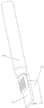
图1为实施例一的焊接连接件的示意图;Fig. 1 is the schematic diagram of the welding connector of the first embodiment;
图2为实施例一与线缆焊接的示意图;FIG. 2 is a schematic diagram of
图3为实施例二的焊接连接件的示意图;FIG. 3 is a schematic diagram of the welding connector of the second embodiment;
图4为实施例二与线缆焊接的示意图;FIG. 4 is a schematic diagram of
图5为现有的焊接连接件的的示意图。FIG. 5 is a schematic diagram of a conventional welded connector.
图中标记:1、接触板,2、焊接板,3、线缆。Labels in the figure: 1. Contact board, 2. Welding board, 3. Cable.
具体实施方式Detailed ways
如图5所示,为现有的焊接连接件,包括用于与导体对接的接触板1和用于与线缆3对焊的焊接板2,接触板1和焊接板2均为扁平板状结构,接触板1和焊接板2沿长度方向的一端对齐焊接,使接触板1和焊接板2形成轴向串联布置。这种结构会导致连接件沿线缆3轴向的尺寸增大,难以满足小型化要求,尤其当导体和线缆3安装在特殊狭小空间时。As shown in FIG. 5, it is an existing welding connector, including a
本发明提供了一种用于连接器的焊接连接件,包括用于与导体对接的接触板1和用于与线缆3对焊的焊接板2,接触板1和焊接板2均为扁平板状结构,接触板1位于焊接板2沿厚度方向的一侧,接触板1的一段条状侧面与焊接板2沿厚度方向一侧的平面焊接,使接触板1沿厚度方向的平面与焊接板2沿厚度方向的平面呈夹角设置。这种结构使接触板1和焊接板2相对于线缆3的轴向形成并行布置结构,与现有的连接件的轴向串联布置相比,能够减少连接件沿线缆3轴向的尺寸,进而缩小产品沿线缆3方向的轴向装配空间,满足小型化要求。The present invention provides a welding connector for a connector, comprising a
实施例一:如图1所示,本实施例的接触板1和焊接板2均为矩形体平板,接触板1沿厚度方向的平面与焊接板2沿厚度方向的平面相互垂直,形成T型结构,并且接触板1远离焊接板2一侧的条状侧面与焊接板2沿厚度方向的平面相互平行。Embodiment 1: As shown in Figure 1, the
如图2所示,焊接板2与线缆3的端部焊接后,接触板1远离焊接板2一侧的条状侧面与线缆3的轴向平行,即线缆3的插线方向与接触板1的接触方向平行。实施例一为具有最标准的形状、应用场景也最为常见的连接形式。As shown in Fig. 2, after the
实施例二:如图3所示,焊接板2为矩形体平板,接触板1的主体形状为梯形体平板,接触板1沿厚度方向的平面与焊接板2沿厚度方向的平面相互垂直,形成T型结构,并且接触板1远离焊接板2一侧的条状侧面与焊接板2沿厚度方向的平面具有120°夹角。Embodiment 2: As shown in Figure 3, the
如图3所示,接触板1的梯形体大端具有与导体相匹配的凹陷结构,并且通过该凹陷结构能够延长接触板1与焊接板2的接触面积,如图所示,由于导体的长度短于焊接板2的长度,因此接触板1上与导体对应的长度也短于焊接板2的长度,此时如果没有设置该凹陷结构,那么接触板1只会与焊接板2沿长度方向靠近前端的表面接触焊接,而通过凹陷结构使得接触板1与焊接板2沿长度方向整体长度的表面都能够接触焊接,提升了接触板1与焊接板2的连接牢固性。As shown in FIG. 3 , the large end of the trapezoid body of the
如图4所示,焊接板2与线缆3的端部焊接后,接触板1远离焊接板2一侧的条状侧面与线缆3的轴向也具有120°夹角,即线缆3的插线方向与接触板1的接触方向具有120°夹角。As shown in FIG. 4 , after the
进一步改变实施例二的接触板1的形状,使接触板1远离焊接板2一侧的条状侧面与焊接板2沿厚度方向的平面具有不同的夹角,就能够使连接件适用于不同插线方向的线缆3。The shape of the
除了实施例一、二之外,本发明的接触板1和焊接板2的形状可以自由变化,如在焊接板上设置一段与线缆相匹配的不规则形对焊平面,就能使焊接板与特殊形状的线缆头焊接,比如线缆头处于恶劣工况下、外设不规则形状的保护装置时,或者是线缆头安装在特殊狭小空间内,导致线缆头需要设置成不规则形状时,本发明的连接件都能够与线缆头和导体可靠连接,并且节约线缆头和导体的装配空间,满足小型化要求,使连接件能够适用于多种情况,提升了适用范围。In addition to the first and second embodiments, the shapes of the
Claims (8)
Priority Applications (1)
| Application Number | Priority Date | Filing Date | Title |
|---|---|---|---|
| CN202210717948.3A CN115207648A (en) | 2022-06-23 | 2022-06-23 | A welding connector for connectors |
Applications Claiming Priority (1)
| Application Number | Priority Date | Filing Date | Title |
|---|---|---|---|
| CN202210717948.3A CN115207648A (en) | 2022-06-23 | 2022-06-23 | A welding connector for connectors |
Publications (1)
| Publication Number | Publication Date |
|---|---|
| CN115207648A true CN115207648A (en) | 2022-10-18 |
Family
ID=83578245
Family Applications (1)
| Application Number | Title | Priority Date | Filing Date |
|---|---|---|---|
| CN202210717948.3A Pending CN115207648A (en) | 2022-06-23 | 2022-06-23 | A welding connector for connectors |
Country Status (1)
| Country | Link |
|---|---|
| CN (1) | CN115207648A (en) |
Citations (9)
| Publication number | Priority date | Publication date | Assignee | Title |
|---|---|---|---|---|
| US20100221933A1 (en) * | 2009-03-02 | 2010-09-02 | Hon Hai Precision Industry Co., Ltd. | Cable connector assembly with grounding device |
| JP2011034876A (en) * | 2009-08-04 | 2011-02-17 | Furukawa Electric Co Ltd:The | Connection structure between flat board and connection terminal and its connection method |
| CN201773973U (en) * | 2010-03-26 | 2011-03-23 | 富士康(昆山)电脑接插件有限公司 | electrical connector |
| CN203631788U (en) * | 2013-08-21 | 2014-06-04 | 富士康(昆山)电脑接插件有限公司 | Socket connector |
| CN204144453U (en) * | 2014-07-23 | 2015-02-04 | 四川永贵科技有限公司 | For the curved formula contact exchanging structure of electric connector |
| CN104641510A (en) * | 2012-09-14 | 2015-05-20 | 矢崎总业株式会社 | Terminal fitting |
| CN204651497U (en) * | 2015-03-12 | 2015-09-16 | 吴伯乐 | The naked termination of super-strength |
| CN204760549U (en) * | 2015-08-06 | 2015-11-11 | 德力西电气有限公司 | Pin configuration |
| WO2018024715A1 (en) * | 2016-08-03 | 2018-02-08 | Gebauer & Griller Kabelwerke Gesellschaft M.B.H. | Ultrasonic welding of a stranded conductor to a contact part by means of a contact plate |
-
2022
- 2022-06-23 CN CN202210717948.3A patent/CN115207648A/en active Pending
Patent Citations (9)
| Publication number | Priority date | Publication date | Assignee | Title |
|---|---|---|---|---|
| US20100221933A1 (en) * | 2009-03-02 | 2010-09-02 | Hon Hai Precision Industry Co., Ltd. | Cable connector assembly with grounding device |
| JP2011034876A (en) * | 2009-08-04 | 2011-02-17 | Furukawa Electric Co Ltd:The | Connection structure between flat board and connection terminal and its connection method |
| CN201773973U (en) * | 2010-03-26 | 2011-03-23 | 富士康(昆山)电脑接插件有限公司 | electrical connector |
| CN104641510A (en) * | 2012-09-14 | 2015-05-20 | 矢崎总业株式会社 | Terminal fitting |
| CN203631788U (en) * | 2013-08-21 | 2014-06-04 | 富士康(昆山)电脑接插件有限公司 | Socket connector |
| CN204144453U (en) * | 2014-07-23 | 2015-02-04 | 四川永贵科技有限公司 | For the curved formula contact exchanging structure of electric connector |
| CN204651497U (en) * | 2015-03-12 | 2015-09-16 | 吴伯乐 | The naked termination of super-strength |
| CN204760549U (en) * | 2015-08-06 | 2015-11-11 | 德力西电气有限公司 | Pin configuration |
| WO2018024715A1 (en) * | 2016-08-03 | 2018-02-08 | Gebauer & Griller Kabelwerke Gesellschaft M.B.H. | Ultrasonic welding of a stranded conductor to a contact part by means of a contact plate |
Similar Documents
| Publication | Publication Date | Title |
|---|---|---|
| TWI358865B (en) | ||
| CN209561646U (en) | A torque bolt type equipment clamp and equipment wiring device | |
| CN101286601A (en) | Plug-in devices for electrical connections | |
| CN2406356Y (en) | Electric connector combination with guiding device | |
| WO2021057366A1 (en) | Power strip | |
| CN115207648A (en) | A welding connector for connectors | |
| WO2020217804A1 (en) | Probe pin, inspection jig, and inspection unit | |
| TWI724868B (en) | Electrical connector assembly and its board end connector and wire end connector | |
| CN2706906Y (en) | Electric connector terminal | |
| CN103414039B (en) | Terminal structure of high-frequency connector | |
| CN114678710A (en) | clamp terminal | |
| CN221552221U (en) | Chip terminal and conductive structure | |
| CN114792901A (en) | Connecting female end structure, male and female terminal and terminal connector | |
| CN222261553U (en) | A two-way plug-in electrical connector | |
| CN218548856U (en) | electrical connector | |
| CN216354817U (en) | Firmly connected contact terminal | |
| JP2022050215A5 (en) | ||
| CN216773574U (en) | Connector assembly and plate end connector and wire end connector thereof | |
| TWM495013U (en) | Card edge connector and card edge connector assembly | |
| CN219477112U (en) | Equipment connector | |
| CN220440042U (en) | Connecting terminal | |
| CN216818664U (en) | Conductive terminal | |
| CN223066567U (en) | A high vibration connector shrapnel | |
| CN205692999U (en) | A kind of connecting terminal block | |
| CN210670762U (en) | Concatenation formula circuit board |
Legal Events
| Date | Code | Title | Description |
|---|---|---|---|
| PB01 | Publication | ||
| PB01 | Publication | ||
| SE01 | Entry into force of request for substantive examination | ||
| SE01 | Entry into force of request for substantive examination |