CN115193739A - Rear cylinder automatic detection equipment and detection method thereof - Google Patents
Rear cylinder automatic detection equipment and detection method thereof Download PDFInfo
- Publication number
- CN115193739A CN115193739A CN202210866762.4A CN202210866762A CN115193739A CN 115193739 A CN115193739 A CN 115193739A CN 202210866762 A CN202210866762 A CN 202210866762A CN 115193739 A CN115193739 A CN 115193739A
- Authority
- CN
- China
- Prior art keywords
- detected
- station
- detection
- cylinder
- manipulator
- Prior art date
- Legal status (The legal status is an assumption and is not a legal conclusion. Google has not performed a legal analysis and makes no representation as to the accuracy of the status listed.)
- Pending
Links
- 238000001514 detection method Methods 0.000 title claims abstract description 219
- 238000012546 transfer Methods 0.000 claims description 67
- 239000002699 waste material Substances 0.000 claims description 36
- 230000002950 deficient Effects 0.000 claims description 33
- 238000007599 discharging Methods 0.000 claims description 28
- 230000007246 mechanism Effects 0.000 claims description 22
- 238000000034 method Methods 0.000 claims description 17
- 230000008569 process Effects 0.000 claims description 17
- 238000013519 translation Methods 0.000 claims description 14
- 235000017166 Bambusa arundinacea Nutrition 0.000 claims description 9
- 235000017491 Bambusa tulda Nutrition 0.000 claims description 9
- 241001330002 Bambuseae Species 0.000 claims description 9
- 235000015334 Phyllostachys viridis Nutrition 0.000 claims description 9
- 239000011425 bamboo Substances 0.000 claims description 9
- 230000007306 turnover Effects 0.000 claims description 7
- 238000012360 testing method Methods 0.000 claims description 4
- 230000009471 action Effects 0.000 claims description 3
- 238000001179 sorption measurement Methods 0.000 claims description 3
- 238000011112 process operation Methods 0.000 claims 2
- 230000032258 transport Effects 0.000 abstract description 4
- 238000007689 inspection Methods 0.000 description 5
- 238000010586 diagram Methods 0.000 description 3
- 230000002159 abnormal effect Effects 0.000 description 1
- 230000009286 beneficial effect Effects 0.000 description 1
- 238000006073 displacement reaction Methods 0.000 description 1
- 238000004134 energy conservation Methods 0.000 description 1
- 238000001746 injection moulding Methods 0.000 description 1
- 238000012986 modification Methods 0.000 description 1
- 230000004048 modification Effects 0.000 description 1
- 238000012797 qualification Methods 0.000 description 1
- 238000010408 sweeping Methods 0.000 description 1
Images




Classifications
-
- B—PERFORMING OPERATIONS; TRANSPORTING
- B07—SEPARATING SOLIDS FROM SOLIDS; SORTING
- B07C—POSTAL SORTING; SORTING INDIVIDUAL ARTICLES, OR BULK MATERIAL FIT TO BE SORTED PIECE-MEAL, e.g. BY PICKING
- B07C5/00—Sorting according to a characteristic or feature of the articles or material being sorted, e.g. by control effected by devices which detect or measure such characteristic or feature; Sorting by manually actuated devices, e.g. switches
- B07C5/02—Measures preceding sorting, e.g. arranging articles in a stream orientating
-
- B—PERFORMING OPERATIONS; TRANSPORTING
- B07—SEPARATING SOLIDS FROM SOLIDS; SORTING
- B07C—POSTAL SORTING; SORTING INDIVIDUAL ARTICLES, OR BULK MATERIAL FIT TO BE SORTED PIECE-MEAL, e.g. BY PICKING
- B07C5/00—Sorting according to a characteristic or feature of the articles or material being sorted, e.g. by control effected by devices which detect or measure such characteristic or feature; Sorting by manually actuated devices, e.g. switches
- B07C5/34—Sorting according to other particular properties
- B07C5/342—Sorting according to other particular properties according to optical properties, e.g. colour
- B07C5/3422—Sorting according to other particular properties according to optical properties, e.g. colour using video scanning devices, e.g. TV-cameras
-
- B—PERFORMING OPERATIONS; TRANSPORTING
- B07—SEPARATING SOLIDS FROM SOLIDS; SORTING
- B07C—POSTAL SORTING; SORTING INDIVIDUAL ARTICLES, OR BULK MATERIAL FIT TO BE SORTED PIECE-MEAL, e.g. BY PICKING
- B07C5/00—Sorting according to a characteristic or feature of the articles or material being sorted, e.g. by control effected by devices which detect or measure such characteristic or feature; Sorting by manually actuated devices, e.g. switches
- B07C5/36—Sorting apparatus characterised by the means used for distribution
- B07C5/361—Processing or control devices therefor, e.g. escort memory
- B07C5/362—Separating or distributor mechanisms
-
- B—PERFORMING OPERATIONS; TRANSPORTING
- B07—SEPARATING SOLIDS FROM SOLIDS; SORTING
- B07C—POSTAL SORTING; SORTING INDIVIDUAL ARTICLES, OR BULK MATERIAL FIT TO BE SORTED PIECE-MEAL, e.g. BY PICKING
- B07C5/00—Sorting according to a characteristic or feature of the articles or material being sorted, e.g. by control effected by devices which detect or measure such characteristic or feature; Sorting by manually actuated devices, e.g. switches
- B07C5/36—Sorting apparatus characterised by the means used for distribution
- B07C5/38—Collecting or arranging articles in groups
-
- B—PERFORMING OPERATIONS; TRANSPORTING
- B07—SEPARATING SOLIDS FROM SOLIDS; SORTING
- B07C—POSTAL SORTING; SORTING INDIVIDUAL ARTICLES, OR BULK MATERIAL FIT TO BE SORTED PIECE-MEAL, e.g. BY PICKING
- B07C2501/00—Sorting according to a characteristic or feature of the articles or material to be sorted
- B07C2501/0063—Using robots
Landscapes
- Engineering & Computer Science (AREA)
- Multimedia (AREA)
- Specific Conveyance Elements (AREA)
Abstract
The invention discloses a rear barrel automatic detection device and a detection method thereof, which sequentially comprise the following steps: the rear cylinders to be detected are stacked on the feeding tray and moved to the central position of the feeding station to wait for detection in sequence; the device comprises a first detection station, a second detection station and a third detection station, wherein a single rear cylinder to be detected is placed on the first detection station, and then the upper top surface of the rear cylinder to be detected is shot and detected by an area array camera and the side wall of the rear cylinder to be detected is shot and detected by a line scanning camera; the turning station is used for turning the rear cylinder to be detected through the first detection station until the bottom surface faces upwards; the second detection station is used for placing the single overturned rear cylinder to be detected on the second detection station, shooting the rear cylinder to be detected by the 3D camera and detecting the lower bottom surface and the inner cavity of the rear cylinder to be detected; and the good product conveying station detects the qualified rear barrel through the first detection station and the second detection station, and the good product conveying station transports and stores the good product.
Description
Technical Field
The invention relates to the technical field of rear cylinder automatic detection, in particular to rear cylinder automatic detection equipment and a detection method thereof.
Background
The rear cylinder is used as an injection molding part with high yield and needs to be connected with other parts in the subsequent process, so that whether the appearance of the rear cylinder is defective or not or whether the appearance of the rear cylinder is convex or not needs to be checked before connection, otherwise, the rear cylinder is connected with other parts to form a whole which becomes defective, and the qualification rate of finished products is greatly influenced.
Need go on the inspection to its upper surface, lateral wall, lower bottom surface and inner chamber to a back section of thick bamboo, traditional check out test set can only detect one of them position of a back section of thick bamboo, just can carry out complete detection to the outward appearance of a back section of thick bamboo through many check out test set and multichannel detection process to lead to the check-out time longer, detection efficiency is lower, and the while detection cost is also higher.
Disclosure of Invention
The invention aims to provide automatic rear cylinder detection equipment and a detection method thereof, which are used for solving the problems that the appearance of a rear cylinder can be completely detected only by a plurality of detection devices and a plurality of detection processes, so that the detection time is longer, the detection efficiency is lower, and the detection cost is higher.
In order to solve the technical problem, the invention provides a rear cylinder automatic detection device, which comprises the following components in sequence:
the rear cylinders to be detected are stacked on the feeding tray and move to the central position of the feeding station to wait for detection in sequence;
the single rear cylinder to be detected is placed on the first detection station, and then the upper top surface of the rear cylinder to be detected and the side wall of the rear cylinder to be detected are shot and detected by the line scanning camera;
the overturning station is used for overturning the rear cylinder to be detected through the first detection station until the lower bottom surface faces upwards;
the second detection station is used for placing the turned single rear cylinder to be detected on the second detection station, and then shooting and detecting the lower bottom surface and the inner cavity of the rear cylinder to be detected by the 3D camera;
a good product conveying station, wherein the rear cylinder which is qualified after being detected by the first detection station and the second detection station is transported and stored by the good product conveying station;
the first detection station and the second detection station are both provided with defective product collecting boxes for collecting and storing defective products detected by the first detection station or the second detection station.
Preferably, the automatic feeding device further comprises a transverse moving mechanism, wherein a feeding manipulator, a first transfer manipulator, a second transfer manipulator and a discharging manipulator are arranged on the transverse moving mechanism; wherein,
the feeding manipulator can transfer the rear cylinder to be detected on the feeding station to the first detection station;
the first transfer manipulator can transfer the rear cylinder to be detected on the first detection station to the overturning station;
the second transfer manipulator can transfer the rear cylinder to be detected on the turnover station to a second detection station;
unloading manipulator can transport the back section of thick bamboo of waiting to detect on the second detection station to yields conveying station.
Preferably, the transverse moving mechanism comprises a fixed plate, a transverse moving plate and a transverse moving cylinder, the transverse moving cylinder drives the transverse moving plate and the feeding mechanical arm, the first transfer mechanical arm, the second transfer mechanical arm and the discharging mechanical arm are arranged on the transverse moving plate at intervals in sequence along the running direction of the detection process and move back and forth along the running direction of the detection process.
Preferably, the transverse moving plate of the transverse moving mechanism is further provided with at least one group of longitudinal moving cylinders, and the longitudinal moving cylinders drive the feeding manipulator, the first transferring manipulator, the second transferring manipulator and the discharging manipulator to synchronously lift along the vertical direction.
Preferably, the feeding manipulator and the first transfer manipulator are negative pressure adsorption manipulators, and the upper top surface of the rear cylinder is adsorbed by a suction nozzle and driven to move; the second transfer manipulator and the blanking manipulator are clamping jaws which clamp the manipulator and drive the side wall of the rear cylinder to move.
Preferably, the feeding station is provided with a feeding tray for stacking rear cylinders to be detected, and two groups of translation cylinders are vertically arranged at the bottom of the feeding tray and drive the feeding tray and the rear cylinders placed on the feeding tray to move along the operation direction of the detection process or the vertical direction of the operation of the detection process through the two groups of translation cylinders.
Preferably, the first detection station is provided with an area-array camera, a line-scan camera and a servo rotating motor;
the area array camera is fixedly arranged above the first detection station, and shoots and detects the upper top surface of the rear cylinder to be detected from top to bottom;
the side wall detection device is fixedly arranged on the side surface of the first detection station, and shoots and detects the side wall of the rear cylinder to be detected from the side surface;
the servo rotating motor is characterized in that a bracket is mounted on a rotating shaft of the servo rotating motor, when a rear cylinder to be detected is placed on the bracket, the servo rotating motor can drive the rear cylinder to be detected to rotate at a constant speed, and the whole side wall of the rear cylinder to be detected is detected in cooperation with the line scanning camera.
Preferably, the first detection station is also provided with a first waste kicking device, the first waste kicking device comprises a first waste kicking cylinder and a first waste kicking manipulator, the first waste kicking manipulator grabs defective products judged by the area array camera or the line sweeping camera, and the defective products are kicked to the defective product collecting box corresponding to the first detection station by the first waste kicking cylinder.
Preferably, the overturning station is provided with an overturning cylinder, the overturning cylinder is fixedly mounted on the side face of the overturning station, and the to-be-detected rear barrel is clamped by an overturning manipulator and then overturned on the overturning station.
Preferably, the upset station still is equipped with the jacking cylinder, the jacking cylinder is through the positioning disk location lift detection back section of thick bamboo, so that the upset of upset cylinder.
Preferably, the second detection station is provided with a 3D camera which is fixedly arranged above the second detection station, and the lower bottom surface and the inner cavity of the rear cylinder to be detected are shot and detected from top to bottom.
Preferably, the second detection station is also equipped with the second and kicks useless device, the useless device is played to the second includes that the second kicks useless cylinder and the useless manipulator is played to the second, by the useless manipulator is played to the second and grabs the warp the defective products that 3D camera detected and judges, and the warp the defective products are played to the second and are removed to with the second detects in the defective products collecting box that the station corresponds.
Preferably, the first detection station and the second detection station are provided with photoelectric switches for detecting whether a rear cylinder to be detected exists on the station.
The invention also provides a detection method of the rear barrel automatic detection equipment, which comprises the following steps:
a step (a): firstly, uniformly placing a plurality of rear cylinders to be detected on a feeding tray, and horizontally moving the feeding tray under the action of two groups of translation cylinders to enable the rear cylinders to be detected in a first row and a first column to reach a designated picking position;
a step (b): then the transverse moving mechanism drives the feeding mechanical arm, the first transfer mechanical arm, the second transfer mechanical arm and the discharging mechanical arm to move towards the direction of the feeding station at the same time until the feeding mechanical arm reaches the position right above the rear cylinder to be detected at the specified picking position;
a step (c): then the longitudinal moving cylinder drives the feeding manipulator, the first transfer manipulator, the second transfer manipulator and the discharging manipulator to descend simultaneously until the feeding manipulator picks up the first row of rear cylinders to be detected in the first row;
a step (d): then, the longitudinal moving cylinder drives the feeding mechanical arm, the first transferring mechanical arm, the second transferring mechanical arm and the discharging mechanical arm to ascend simultaneously, and the transverse moving mechanism drives the feeding mechanical arm, the first transferring mechanical arm, the second transferring mechanical arm and the discharging mechanical arm to move towards the direction of a good product conveying station simultaneously until the feeding mechanical arm reaches the position right above the first detection station;
a step (e): then, the longitudinal moving cylinder drives the feeding mechanical arm, the first transfer mechanical arm, the second transfer mechanical arm and the discharging mechanical arm to descend simultaneously until a rear cylinder to be detected is placed on a first detection station;
step (f): then starting an area array camera to shoot and detect the upper top surface of the to-be-detected rear barrel on the first detection station;
step (g): then starting a line scanning camera to shoot and detect the side wall of the rear cylinder to be detected on the first detection station, and driving the rear cylinder to be detected to rotate at a constant speed by a servo rotating motor while shooting by the line scanning camera, so that the whole side wall of the rear cylinder to be detected is detected;
a step (h): when the area-array camera and the line-scan camera are qualified in detection, the to-be-detected rear cylinder enters the overturning station; when any one of the area-array camera and the line-scan camera is unqualified in detection, the rear cylinder to be detected can be kicked and removed to a defective product collecting box corresponding to the first detection station by the first kicking and waste removing device;
step (i): the feeding tray is driven by the two groups of translation cylinders to move while the first detection station detects, so that the first row and the second row of rear cylinders to be detected reach the designated picking position;
a step (j): the transverse moving mechanism drives the feeding mechanical arm, the first transfer mechanical arm, the second transfer mechanical arm and the discharging mechanical arm to move towards the direction of the feeding station at the same time until the feeding mechanical arm reaches the position right above the rear cylinder to be detected at the specified picking position;
step (k): the longitudinal moving cylinder drives the feeding mechanical arm, the first transfer mechanical arm, the second transfer mechanical arm and the discharging mechanical arm to descend simultaneously until the feeding mechanical arm picks up a first row of second rows of rear cylinders to be detected, meanwhile, the first transfer mechanical arm picks up qualified rear cylinders to be detected through the first detection station, the operation of the step (d) and the operation of the step (e) are repeated, the first row of second rows of rear cylinders to be detected are moved to the first detection station, and at the moment, the qualified rear cylinders to be detected through the first detection station are moved to the turnover station;
step (l): the first row and the second row of rear cylinders to be detected are detected in the first detection station by repeating the step (f) and the step (g), and meanwhile, qualified rear cylinders to be detected are turned over on the turning station by the turning cylinder until the bottom surface faces upwards;
step (m): repeating the operation of the step (j) and the operation of the step (k), wherein a feeding mechanical arm picks up the first row and the third row of rear cylinders to be detected to a first detection station, a first transfer mechanical arm picks up the qualified rear cylinders to be detected to a turnover station through the first detection station, and a second transfer mechanical arm picks up the rear cylinders to be detected on the turnover station to a second detection station;
and (n): shooting and detecting the lower bottom surface and the inner cavity of the rear cylinder to be detected on the second detection station by using a 3D camera;
step (o): when the 3D camera is detected to be qualified, the to-be-detected rear barrel enters a good product conveying station; when the 3D camera is unqualified in detection, the rear cylinder to be detected can be kicked and removed by the second kicking waste device into a defective product collecting box corresponding to the second detection station;
step (p): and repeating the above operations to sequentially detect the rear cylinder to be detected in the feeding tray.
Compared with the prior art, the invention has the beneficial effects that:
1. the automatic rear barrel detection equipment can sequentially detect the upper top surface, the complete side wall, the lower bottom surface and the inner cavity of a rear barrel to be detected, one set of equipment can solve all detection items, the detection speed is improved, and the detection cost is reduced;
2. the detection method of the automatic rear cylinder detection equipment can be used for detecting large batches of rear cylinder products, stations in the detection process are carried out in a staggered mode, and each station is used for detecting the products in each process, so that the detection efficiency is greatly improved.
Drawings
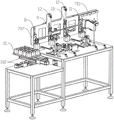
FIG. 1 is a schematic structural diagram of a first view angle of a rear barrel automatic detection device provided by the present invention;
FIG. 2 is a schematic structural diagram of a second view angle of the rear barrel automatic detection device provided by the present invention;
FIG. 3 is a front view of a rear drum automatic detection device provided by the present invention;
FIG. 4 is a schematic structural diagram of a detection station of the automatic rear drum detection device provided by the invention;
FIG. 5 is a front view of a detection station of the automatic rear-drum detection device provided by the invention;
FIG. 6 is a top view of a detection station of the automatic rear drum detection device provided by the invention.
In the figure: 1. a feeding station; 2. a first detection station; 3. turning over a station; 4. a second detection station; 5. a good product conveying station; 6. a defective product collection box; 7. a traversing mechanism; 8. a feeding manipulator; 9. a first transfer robot; 10. a second transfer robot; 11. a feeding manipulator; 12. a longitudinally moving cylinder; 13. a first waste kicking device; 14. a second waste kicking device; 15. a photoelectric switch; 101. a feeding tray; 102. a translation cylinder; 201. an area-array camera; 202. a line scan camera; 203. a servo rotating motor; 301. turning over the air cylinder; 302. jacking a cylinder; 401. a 3D camera; 701. a fixing plate; 702. transversely moving the plate; 703. and (5) transversely moving the cylinder.
Detailed Description
The invention is described in further detail below with reference to the following figures and specific examples. Advantages and features of the present invention will become apparent from the following description and from the claims. It is to be noted that the drawings are in a very simplified form and are not to precise scale, which is merely for the purpose of facilitating and distinctly claiming the embodiments of the present invention.
In the description of the present invention, it is to be understood that the terms "central," "longitudinal," "lateral," "upper," "lower," "front," "rear," "left," "right," "vertical," "horizontal," "top," "bottom," "inner," "outer," and the like are used in the orientations and positional relationships indicated in the drawings, which are based on the orientations and positional relationships indicated in the drawings, and are used for convenience in describing the present invention and for simplicity in description, but do not indicate or imply that the device or element so referred to must have a particular orientation, be constructed in a particular orientation, and be operated, and thus should not be construed as limiting the present invention. Furthermore, the terms "first", "second", etc. are used for descriptive purposes only and are not to be construed as indicating or implying relative importance or implicitly indicating the number of technical features indicated. Thus, a feature defined as "first," "second," etc. may explicitly or implicitly include one or more of that feature. In the description of the present invention, "a plurality" means two or more unless otherwise specified.
In the description of the present invention, it should be noted that, unless otherwise explicitly specified or limited, the terms "mounted," "connected," and "connected" are to be construed broadly and may be, for example, fixedly connected, detachably connected, or integrally connected; can be mechanically or electrically connected; they may be connected directly or indirectly through intervening media, or they may be interconnected between two elements. The specific meaning of the above terms in the present invention can be understood by those of ordinary skill in the art through specific situations.
Example one
The invention provides a rear barrel automatic detection device, please refer to fig. 1-3, which comprises the following components in sequence:
the device comprises a feeding station 1, a plurality of rear cylinders to be detected are stacked on a feeding tray and moved to the central position of the feeding station 1 to wait for detection in sequence;
the single rear cylinder to be detected is placed on the first detection station 2, and then the upper top surface of the rear cylinder to be detected is shot and detected by the area-array camera and the side wall of the rear cylinder to be detected is shot and detected by the line-scan camera;
the turning station 3 is used for turning the rear cylinder to be detected, which is detected by the first detection station 2, until the bottom surface faces upwards;
the second detection station 4 is used for placing the single overturned rear cylinder to be detected on the second detection station 4, shooting the rear cylinder to be detected by the 3D camera and detecting the lower bottom surface and the inner cavity of the rear cylinder to be detected;
a good product conveying station 5, wherein qualified rear cylinders are detected by the first detection station 2 and the second detection station 4, and are transported and stored by the good product conveying station 5;
the first detection station 2 and the second detection station 4 are both provided with a defective product collecting box 6 for collecting and storing defective products detected by the first detection station 2 or the second detection station 4.
Specifically, referring to fig. 4 to 6, the rear cylinder automatic detection equipment further includes a transverse moving mechanism 7, and the transverse moving mechanism 7 is provided with a feeding manipulator 8, a first transfer manipulator 9, a second transfer manipulator 10 and a discharging manipulator 11; wherein,
the feeding manipulator 8 can transport the rear cylinder to be detected on the feeding station 1 to the first detection station 2;
the first transfer manipulator 9 can transfer the rear cylinder to be detected on the first detection station 2 to the overturning station 3;
the second transfer manipulator 10 can transfer the rear cylinder to be detected on the turnover station 3 to the second detection station 4;
the blanking manipulator 11 can transport the rear cylinder to be detected on the second detection station 4 to the good product conveying station 5.
Further, the transverse moving mechanism 7 includes a fixing plate 701, a transverse moving plate 702 and a transverse moving cylinder 703, the transverse moving cylinder 703 drives the transverse moving plate 702 and the feeding manipulator 8, the first transferring manipulator 9, the second transferring manipulator 10 and the discharging manipulator 11 which are sequentially arranged on the transverse moving plate 702 along the running direction of the detection process at intervals move back and forth along the running direction of the detection process.
Further, at least one group of longitudinal moving cylinders 12 is further arranged on the transverse moving plate 702 of the transverse moving mechanism 7, and the feeding manipulator 8, the first transferring manipulator 9, the second transferring manipulator 10 and the discharging manipulator 11 are driven to synchronously lift and descend along the vertical direction through the longitudinal moving cylinders 12.
The feeding manipulator 8 and the first transfer manipulator 9 are negative pressure adsorption manipulators, and the upper top surface of the rear cylinder is adsorbed by a suction nozzle and driven to move; the second transfer manipulator 10 and the blanking manipulator 11 are clamping jaws which clamp the rear barrel and drive the rear barrel to move.
Specifically, the feeding station 1 is equipped with a feeding tray 101 and is used for stacking rear cylinders to be detected, two sets of translation cylinders 102 are vertically arranged at the bottom of the feeding tray 101 and drive the feeding tray 101 and the rear cylinders placed on the feeding tray 101 to move along the running direction of the detection process or the vertical direction of the detection process through the two sets of translation cylinders 102, and the feeding manipulator 8 can sequentially pick up the rear cylinders on the feeding tray 101 at the same position at each time through translation and send the rear cylinders to the first detection station 2.
Specifically, the first detection station 2 is provided with an area-array camera 201, a line-scan camera 202 and a servo rotating motor 203;
the area array camera 201 is fixedly arranged above the first detection station 2, and shoots and detects the upper top surface of the rear cylinder to be detected from top to bottom;
the side wall detection device is fixedly arranged on the side surface of the first detection station 2, and is used for shooting and detecting the side wall of the rear cylinder to be detected from the side surface;
a bracket is arranged on a rotating shaft of the servo rotating motor 203, when a rear cylinder to be detected is placed on the bracket, the servo rotating motor 203 can drive the rear cylinder to be detected to rotate at a constant speed, and the whole side wall of the rear cylinder to be detected is detected in cooperation with the line scanning camera 202.
In some embodiments, the rotating shaft of the servo rotating motor 203 has a certain play stroke along the axial direction, so that the rear cylinder with a large end and a small end can adapt to the requirement of focusing of the line-scan camera 202.
In some embodiments, the first inspection station 2 is further equipped with a first shift cylinder for pushing the first inspection station 2 to move along a horizontal plane, so that the position of the product to be inspected matches with the shooting position of the area-array camera 201 or the line-scan camera 202.
Specifically, the first detection station 2 is further equipped with a first waste kicking device 13, the first waste kicking device 13 includes a first waste kicking cylinder and a first waste kicking manipulator, the first waste kicking manipulator grabs the defective products detected and determined by the area-array camera 201 or the line scanning camera 202, and kicks the defective products into the defective product collection box 6 corresponding to the first detection station 2 through the first waste kicking cylinder.
Specifically, the overturning station 3 is provided with an overturning cylinder 301, the overturning cylinder 301 is fixedly installed on the side face of the overturning station 3, and the overturning manipulator clamps the rear cylinder to be detected and then overturns the rear cylinder to be detected on the overturning station 3.
Specifically, the overturning station 3 is further provided with a jacking cylinder 302, and the jacking cylinder 302 is used for positioning and lifting a detection rear cylinder through a positioning plate so as to overturn the overturning cylinder 301.
Specifically, the second detection station 4 is provided with a 3D camera 401 which is fixedly mounted above the second detection station 4, and the lower bottom surface and the inner cavity of the rear cylinder to be detected are shot and detected from top to bottom.
In some embodiments, the second inspection station 4 is further equipped with a second displacement cylinder for pushing the second inspection station 2 to move along a horizontal plane so that the position of the product to be inspected matches the shooting position of the 3D camera 401.
Further, the second detection station 4 is further equipped with a second waste kicking device 14, the second waste kicking device 14 includes a second waste kicking cylinder and a second waste kicking manipulator, the second waste kicking manipulator grabs the defective products detected and determined by the 3D camera 401, and kicks the defective products into the defective product collection box 6 corresponding to the second detection station 4 through the second waste kicking cylinder.
Specifically, the first detection station 2 and the second detection station 4 are both provided with a photoelectric switch 15 for detecting whether a rear cylinder to be detected exists on the stations; when detecting that there is no rear cylinder to be detected on the station, the detection equipment equipped on the station stops the detection, so that the purpose of energy conservation is achieved, and when the photoelectric switch 15 continuously detects that the rear cylinder to be detected cannot be detected, the equipment is judged to be abnormal in operation, and an alarm is given to remind an operator to overhaul.
This automatic check out test set of back section of thick bamboo can treat the last top surface, complete lateral wall, bottom surface and the inner chamber of a back section of thick bamboo that detects and detect in proper order, and all detection items just can be solved to one set of equipment, when improving detection speed, have reduced the detection cost.
Example two
The invention also provides a detection method of the rear barrel automatic detection equipment, referring to fig. 1-6, comprising the following steps:
a step (a): firstly, uniformly placing a plurality of rear cylinders to be detected on a feeding tray 101, and horizontally moving the feeding tray 101 under the action of two groups of translation cylinders 102 to enable the rear cylinders to be detected in a first row and a first column to reach a designated picking position;
step (b): then, the transverse moving mechanism 7 drives the feeding manipulator 8, the first transfer manipulator 9, the second transfer manipulator 10 and the discharging manipulator 11 to simultaneously move towards the direction of the feeding station 1 until the feeding manipulator 8 reaches the position right above the to-be-detected rear barrel at the specified picking position;
step (c): then the longitudinal moving cylinder 12 drives the feeding manipulator 8, the first transfer manipulator 9, the second transfer manipulator 10 and the discharging manipulator 11 to descend simultaneously until the feeding manipulator 8 picks up the first row of rear cylinders to be detected in the first row;
step (d): then, a longitudinal moving cylinder 12 drives a feeding manipulator 8, a first transferring manipulator 9, a second transferring manipulator 10 and a discharging manipulator 11 to ascend simultaneously, and a transverse moving mechanism 7 drives the feeding manipulator 8, the first transferring manipulator 9, the second transferring manipulator 10 and the discharging manipulator 11 to move towards the direction of a good product conveying station 5 simultaneously until the feeding manipulator 8 reaches the position right above a first detection station 2;
a step (e): then, the longitudinal moving cylinder 12 drives the feeding manipulator 8, the first transferring manipulator 9, the second transferring manipulator 10 and the discharging manipulator 11 to descend simultaneously until the rear cylinder to be detected is placed on the first detection station 2;
a step (f): then, starting the area-array camera 201 to shoot and detect the upper top surface of the rear cylinder to be detected on the first detection station 2;
a step (g): then, starting the line scanning camera 202 to shoot and detect the side wall of the to-be-detected rear cylinder on the first detection station 2, and driving the to-be-detected rear cylinder to rotate at a constant speed by the servo rotating motor 203 while shooting by the line scanning camera 202, so that the whole side wall of the to-be-detected rear cylinder is detected;
a step (h): when the area-array camera 201 and the line-scan camera 202 are qualified in detection, the rear cylinder to be detected enters the turning station 3; when any one of the area-array camera 201 or the line-scan camera 202 is unqualified in detection, the to-be-detected rear cylinder can be kicked off by the first kicking-off device 13 to the defective product collecting box 6 corresponding to the first detection station 2;
step (i): when the first detection station 2 detects, the two groups of translation cylinders 102 drive the feeding tray 101 to move, so that the rear cylinders to be detected in the first row and the second row reach the designated picking position;
step (j): the transverse moving mechanism 7 drives the feeding manipulator 8, the first transfer manipulator 9, the second transfer manipulator 10 and the discharging manipulator 11 to move towards the direction of the feeding station 1 at the same time until the feeding manipulator 8 reaches the position right above the rear cylinder to be detected at the specified picking position;
step (k): the longitudinal moving cylinder 12 drives the feeding manipulator 8, the first transfer manipulator 9, the second transfer manipulator 10 and the discharging manipulator 11 to descend simultaneously until the feeding manipulator 8 picks up a first row and a second row of rear cylinders to be detected, meanwhile, the first transfer manipulator 9 picks up qualified rear cylinders to be detected through the first detection station 2, the operation of the step (d) and the operation of the step (e) are repeated, the first row and the second row of rear cylinders to be detected are moved to the first detection station 2, and at the moment, the qualified rear cylinders to be detected through the first detection station 2 are moved to the overturning station 3;
step (l): the first row and the second row of rear cylinders to be detected are detected in the first detection station 2 by repeating the step (f) and the step (g), and meanwhile, qualified rear cylinders to be detected are detected in the first detection station 2 and are overturned to the lower bottom surface of the rear cylinder to be detected to be upward in the overturning station 3 through the overturning cylinder 301;
step (m): repeating the operation of the step (j) and the operation of the step (k), picking the first row and the third row of the rear cylinders to be detected to the first detection station 2 by the feeding manipulator 8, picking the qualified rear cylinders to be detected to the overturning station 3 by the first transfer manipulator 9, and picking the rear cylinders to be detected on the overturning station 3 to the second detection station 4 by the second transfer manipulator 10;
and (n): shooting and detecting the lower bottom surface and the inner cavity of the rear cylinder to be detected by the 3D camera 401 at the second detection station 4;
step (o): when the 3D camera 401 is qualified, the barrel to be detected enters a good product conveying station 5; when the 3D camera 401 is unqualified in detection, the to-be-detected rear cylinder can be kicked off by the second kicking waste device 14 to the defective product collecting box 6 corresponding to the second detection station 4;
step (p): the operations are repeated to sequentially detect the rear cylinder to be detected in the feeding tray 101.
The detection method of the rear barrel automatic detection equipment can be used for detecting large batches of rear barrel products, stations in the detection process are carried out in a staggered mode, and each station is used for detecting the products in each process, so that the detection side efficiency is greatly improved.
The above description is only for the purpose of describing the preferred embodiment of the present invention, and is not intended to limit the scope of the present invention, and any variations and modifications made by those skilled in the art based on the above disclosure are intended to fall within the scope of the appended claims.
Claims (10)
1. The utility model provides a back section of thick bamboo automatic check out test set which characterized in that, including setting gradually:
the device comprises a feeding station (1), a plurality of rear cylinders to be detected are stacked on a feeding tray and moved to the central position of the feeding station (1) to wait for sequential detection;
the single rear cylinder to be detected is placed on the first detection station (2), and then the single rear cylinder to be detected is shot by the area-array camera and detects the upper top surface of the rear cylinder to be detected and the side wall of the rear cylinder to be detected by the line-scan camera;
the turnover station (3) is used for turning the rear cylinder to be detected, which is detected by the first detection station (2), over until the bottom surface faces upwards;
the second detection station (4), the single reversed rear cylinder to be detected is placed on the second detection station (4), and then the lower bottom surface and the inner cavity of the rear cylinder to be detected are shot and detected by the 3D camera;
the good product conveying station (5) is used for detecting qualified rear cylinders through the first detection station (2) and the second detection station (4), and the good product conveying station (5) is used for transporting and storing the qualified rear cylinders;
the first detection station (2) and the second detection station (4) are both provided with a defective product collecting box (6) for collecting and storing defective products detected by the first detection station (2) or the second detection station (4).
2. The automatic rear-drum detection device according to claim 1, further comprising a traversing mechanism (7), wherein the traversing mechanism (7) is provided with a feeding manipulator (8), a first transfer manipulator (9), a second transfer manipulator (10) and a discharging manipulator (11); wherein,
the feeding manipulator (8) can transfer the rear cylinder to be detected on the feeding station (1) to the first detection station (2);
the first transfer manipulator (9) can transfer the rear cylinder to be detected on the first detection station (2) to the overturning station (3);
the second transfer manipulator (10) can transfer the rear cylinder to be detected on the overturning station (3) to the second detection station (4);
the blanking mechanical arm (11) can transfer the rear cylinders to be detected on the second detection station (4) to a good product conveying station (5).
3. The automatic rear-drum detecting device according to claim 2, characterized in that the traverse mechanism (7) comprises a fixed plate (701), a traverse plate (702) and a traverse cylinder (703), and the traverse cylinder (703) drives the traverse plate (702) and the feeding robot (8), the first transfer robot (9), the second transfer robot (10) and the discharging robot (11) arranged on the traverse plate (702) and arranged on the traverse plate (702) at intervals in sequence along the detecting process running direction to reciprocate along the detecting process running direction.
4. The automatic rear-drum detection device as claimed in claim 3, characterized in that at least one set of longitudinal-movement cylinders (12) is further disposed on the traverse plate (702) of the traverse mechanism (7), and the feeding manipulator (8), the first transfer manipulator (9), the second transfer manipulator (10) and the discharging manipulator (11) are driven by the longitudinal-movement cylinders (12) to synchronously lift in the vertical direction.
5. The automatic rear-drum detection equipment according to claim 2, characterized in that the loading manipulator (8) and the first transfer manipulator (9) are negative pressure adsorption manipulators, and the upper top surface of the rear drum is adsorbed by a suction nozzle and is driven to move; the second transfer manipulator (10) and the blanking manipulator (11) are clamping jaw clamping manipulators which move by clamping the side wall of the rear cylinder.
6. The automatic rear cylinder detection equipment according to claim 1, characterized in that the feeding station (1) is equipped with a feeding tray (101) for stacking rear cylinders to be detected, and two sets of translation cylinders (102) are vertically arranged at the bottom of the feeding tray (101) to drive the feeding tray (101) and the rear cylinders placed on the feeding tray (101) to move along the detection process operation direction or the vertical direction of the detection process operation through the two sets of translation cylinders (102).
7. The automatic rear cylinder detection equipment according to claim 1, characterized in that the first detection station (2) is equipped with an area-array camera (201), a line-scan camera (202) and a servo rotating motor (203);
the area array camera (201) is fixedly arranged above the first detection station (2), and shoots and detects the upper top surface of the rear cylinder to be detected from top to bottom;
the side wall detection device is fixedly arranged on the side surface of the first detection station (2), and is used for shooting and detecting the side wall of the rear cylinder to be detected from the side surface;
the rotary shaft of the servo rotary motor (203) is provided with a bracket, when a rear cylinder to be detected is placed on the bracket, the servo rotary motor (203) can drive the rear cylinder to be detected to rotate at a constant speed, and the whole side wall of the rear cylinder to be detected is detected in cooperation with the linear scanning camera (202).
8. The automatic rear cylinder detection equipment according to claim 7, wherein the first detection station (2) is further equipped with a first waste kicking device (13), the first waste kicking device (13) comprises a first waste kicking cylinder and a first waste kicking manipulator, the first waste kicking manipulator grabs the defective products detected and determined by the area-array camera (201) or the line-scanning camera (202), and kicks the defective products out into the defective product collection box (6) corresponding to the first detection station (2) through the first waste kicking cylinder;
the second detection station (4) is also provided with a second waste kicking device (14), the second waste kicking device (14) comprises a second waste kicking cylinder and a second waste kicking manipulator, the second waste kicking manipulator grabs defective products judged through the 3D camera detection, and the defective products are kicked to the defective product collecting box (6) corresponding to the second detection station (4) through the second waste kicking cylinder.
9. The automatic rear cylinder detection equipment as claimed in claim 1, wherein the turning station (3) is provided with a turning cylinder (301), the turning cylinder (301) is fixedly installed on the side surface of the turning station (3), and the rear cylinder to be detected is clamped by a turning manipulator and then turned over on the turning station (3);
upset station (3) still are equipped with jacking cylinder (302), jacking cylinder (302) lift through the positioning disk location and detect a back section of thick bamboo to be convenient for the upset of upset cylinder (301).
10. The detection method of the rear barrel automatic detection equipment as claimed in any one of claims 1 to 9, characterized by comprising the following steps:
step (a): firstly, uniformly placing a plurality of rear cylinders to be detected on a feeding tray (101), and horizontally moving the feeding tray (101) under the action of two groups of translation cylinders (102) to enable the rear cylinders to be detected in a first row and a first column to reach a specified picking position;
step (b): then, the transverse moving mechanism (7) drives the feeding mechanical arm (8), the first transfer mechanical arm (9), the second transfer mechanical arm (10) and the discharging mechanical arm (11) to move towards the direction of the feeding station (1) at the same time until the feeding mechanical arm (8) reaches the position right above the rear cylinder to be detected at the designated picking position;
a step (c): then the longitudinal moving cylinder (12) drives the feeding mechanical arm (8), the first transfer mechanical arm (9), the second transfer mechanical arm (10) and the discharging mechanical arm (11) to descend simultaneously until the feeding mechanical arm (8) picks up the first row of rear cylinders to be detected in the first row;
step (d): then, a longitudinal moving cylinder (12) drives a feeding mechanical arm (8), a first transferring mechanical arm (9), a second transferring mechanical arm (10) and a discharging mechanical arm (11) to ascend simultaneously, and a transverse moving mechanism (7) drives the feeding mechanical arm (8), the first transferring mechanical arm (9), the second transferring mechanical arm (10) and the discharging mechanical arm (11) to move towards the direction of a good product conveying station (5) simultaneously until the feeding mechanical arm (8) reaches the position right above a first detection station (2);
a step (e): then, a longitudinal moving cylinder (12) drives a feeding manipulator (8), a first transferring manipulator (9), a second transferring manipulator (10) and a discharging manipulator (11) to descend simultaneously until a rear cylinder to be detected is placed on a first detection station (2);
step (f): then starting an area-array camera (201) to shoot and detect the upper top surface of the rear cylinder to be detected on the first detection station (2);
step (g): then, starting a line scanning camera (202) to shoot and detect the side wall of a rear cylinder to be detected on the first detection station (2), and driving the rear cylinder to be detected to rotate at a constant speed by a servo rotating motor (203) while shooting by the line scanning camera (202), so that the whole side wall of the rear cylinder to be detected is detected;
a step (h): when the area-array camera (201) and the line-scan camera (202) are qualified in detection, the rear cylinder to be detected enters the overturning station (3); when any one of the area-array camera (201) or the line-scanning camera (202) is unqualified in detection, the rear cylinder to be detected can be kicked off to a defective product collecting box (6) corresponding to the first detection station (2) by the first kicking-off device (13);
step (i): the feeding tray (101) is driven by two groups of translation cylinders (102) to move while the first detection station (2) detects, so that the rear cylinders to be detected in the first row and the second row reach the designated picking position;
step (j): the transverse moving mechanism (7) drives the feeding mechanical arm (8), the first transfer mechanical arm (9), the second transfer mechanical arm (10) and the blanking mechanical arm (11) to move towards the direction of the feeding station (1) at the same time until the feeding mechanical arm (8) reaches the position right above the rear barrel to be detected at the appointed picking position;
step (k): the longitudinal moving cylinder (12) drives the feeding mechanical arm (8), the first transferring mechanical arm (9), the second transferring mechanical arm (10) and the blanking mechanical arm (11) to descend simultaneously until the feeding mechanical arm (8) picks up a first row of second rows of rear cylinders to be detected, meanwhile, the first transferring mechanical arm (9) picks up the qualified rear cylinders to be detected through the first detection station (2), the operation of the step (d) and the step (e) is repeated, the first row of second rows of rear cylinders to be detected are moved to the first detection station (2), and the qualified rear cylinders to be detected through the first detection station (2) are moved to the turnover station (3);
step (l): the first row and the second row of rear cylinders to be detected are detected in the first detection station (2) by repeating the step (f) and the step (g), and meanwhile, qualified rear cylinders to be detected are detected in the first detection station (2) and are overturned on the overturning station (3) through the overturning cylinder (301) until the bottom surface faces upwards;
a step (m): repeating the operation of the step (j) and the operation of the step (k), picking up the first row and the third row of rear cylinders to be detected to the first detection station (2) by the feeding manipulator (8), picking up qualified rear cylinders to be detected to the overturning station (3) by the first detection station (2) by the first transfer manipulator (9), and picking up the rear cylinders to be detected on the overturning station (3) to the second detection station (4) by the second transfer manipulator (10);
and (n): shooting the rear barrel to be detected on the second detection station (4) by a 3D camera and detecting the lower bottom surface and the inner cavity of the rear barrel to be detected;
step (o): when the 3D camera is qualified, the cylinder to be detected enters a good product conveying station (5); when the 3D camera is unqualified in detection, the rear cylinder to be detected can be kicked off to a defective product collecting box (6) corresponding to the second detection station (4) by the second waste kicking device (14);
step (p): and repeating the operation to sequentially detect the rear cylinder to be detected in the feeding tray (101).
Priority Applications (1)
| Application Number | Priority Date | Filing Date | Title |
|---|---|---|---|
| CN202210866762.4A CN115193739A (en) | 2022-07-22 | 2022-07-22 | Rear cylinder automatic detection equipment and detection method thereof |
Applications Claiming Priority (1)
| Application Number | Priority Date | Filing Date | Title |
|---|---|---|---|
| CN202210866762.4A CN115193739A (en) | 2022-07-22 | 2022-07-22 | Rear cylinder automatic detection equipment and detection method thereof |
Publications (1)
| Publication Number | Publication Date |
|---|---|
| CN115193739A true CN115193739A (en) | 2022-10-18 |
Family
ID=83583960
Family Applications (1)
| Application Number | Title | Priority Date | Filing Date |
|---|---|---|---|
| CN202210866762.4A Pending CN115193739A (en) | 2022-07-22 | 2022-07-22 | Rear cylinder automatic detection equipment and detection method thereof |
Country Status (1)
| Country | Link |
|---|---|
| CN (1) | CN115193739A (en) |
Cited By (1)
| Publication number | Priority date | Publication date | Assignee | Title |
|---|---|---|---|---|
| CN115541600A (en) * | 2022-11-30 | 2022-12-30 | 杭州未名信科科技有限公司 | Product detection device |
-
2022
- 2022-07-22 CN CN202210866762.4A patent/CN115193739A/en active Pending
Cited By (1)
| Publication number | Priority date | Publication date | Assignee | Title |
|---|---|---|---|---|
| CN115541600A (en) * | 2022-11-30 | 2022-12-30 | 杭州未名信科科技有限公司 | Product detection device |
Similar Documents
| Publication | Publication Date | Title |
|---|---|---|
| CN111606021B (en) | Feeding and discharging device | |
| CN111606022B (en) | Feeding and discharging device | |
| CN112298889A (en) | High-speed light-weight type storage equipment | |
| CN109462756A (en) | A kind of camera module automatic detecting machine | |
| CN111921877B (en) | Code scanning detection method for automatic storage code scanning classification equipment | |
| CN111921876B (en) | Code scanning detection system of code scanning classification equipment for automatic warehousing | |
| CN111921878B (en) | Automatic warehouse code scanning classification method | |
| CN115193739A (en) | Rear cylinder automatic detection equipment and detection method thereof | |
| CN211789316U (en) | Automatic blanking equipment for high-temperature formation of battery | |
| CN111477942A (en) | Automatic blanking equipment for high-temperature formation of battery | |
| CN218331285U (en) | Rear cylinder appearance detection mechanism | |
| CN109677908B (en) | Overturning and carrying device, electroacoustic transducer sealing cover, testing and stacking equipment and method | |
| CN117825403A (en) | High-speed square battery cell appearance detection machine and detection method | |
| CN114700285B (en) | Chip sorting device, equipment and method | |
| CN208082922U (en) | A kind of metallic plug piler | |
| CN216971270U (en) | Wireless charging coil detection device | |
| CN110733689A (en) | device packaging equipment | |
| CN111921875B (en) | Automatic code sorting equipment is swept in storage | |
| CN210653951U (en) | Full-automatic buzzer vision and audio detection equipment | |
| CN217866866U (en) | Automatic turnover detection linkage device for rear cylinder | |
| CN110342039B (en) | Full-automatic buzzer vision and audio detection equipment | |
| CN217437095U (en) | Take visual detection's material equipment of picking up | |
| CN112850132A (en) | Automatic loading code scanning binding battery inserting support system and method | |
| CN116972605B (en) | Lithium battery baking and drying production line, stacking type fixture tray disassembling equipment and method | |
| CN213922606U (en) | High-speed light-weight type storage equipment |
Legal Events
| Date | Code | Title | Description |
|---|---|---|---|
| PB01 | Publication | ||
| PB01 | Publication | ||
| SE01 | Entry into force of request for substantive examination | ||
| SE01 | Entry into force of request for substantive examination |