CN115166028B - Brake disc eddy current testing machine - Google Patents
Brake disc eddy current testing machine Download PDFInfo
- Publication number
- CN115166028B CN115166028B CN202211086539.4A CN202211086539A CN115166028B CN 115166028 B CN115166028 B CN 115166028B CN 202211086539 A CN202211086539 A CN 202211086539A CN 115166028 B CN115166028 B CN 115166028B
- Authority
- CN
- China
- Prior art keywords
- detection
- eddy current
- brake disc
- fixed
- detection mechanism
- Prior art date
- Legal status (The legal status is an assumption and is not a legal conclusion. Google has not performed a legal analysis and makes no representation as to the accuracy of the status listed.)
- Active
Links
Images


Classifications
-
- G—PHYSICS
- G01—MEASURING; TESTING
- G01N—INVESTIGATING OR ANALYSING MATERIALS BY DETERMINING THEIR CHEMICAL OR PHYSICAL PROPERTIES
- G01N27/00—Investigating or analysing materials by the use of electric, electrochemical, or magnetic means
- G01N27/72—Investigating or analysing materials by the use of electric, electrochemical, or magnetic means by investigating magnetic variables
- G01N27/82—Investigating or analysing materials by the use of electric, electrochemical, or magnetic means by investigating magnetic variables for investigating the presence of flaws
- G01N27/90—Investigating or analysing materials by the use of electric, electrochemical, or magnetic means by investigating magnetic variables for investigating the presence of flaws using eddy currents
- G01N27/904—Investigating or analysing materials by the use of electric, electrochemical, or magnetic means by investigating magnetic variables for investigating the presence of flaws using eddy currents with two or more sensors
-
- G—PHYSICS
- G01—MEASURING; TESTING
- G01N—INVESTIGATING OR ANALYSING MATERIALS BY DETERMINING THEIR CHEMICAL OR PHYSICAL PROPERTIES
- G01N27/00—Investigating or analysing materials by the use of electric, electrochemical, or magnetic means
- G01N27/72—Investigating or analysing materials by the use of electric, electrochemical, or magnetic means by investigating magnetic variables
- G01N27/82—Investigating or analysing materials by the use of electric, electrochemical, or magnetic means by investigating magnetic variables for investigating the presence of flaws
- G01N27/90—Investigating or analysing materials by the use of electric, electrochemical, or magnetic means by investigating magnetic variables for investigating the presence of flaws using eddy currents
- G01N27/9006—Details, e.g. in the structure or functioning of sensors
-
- G—PHYSICS
- G01—MEASURING; TESTING
- G01N—INVESTIGATING OR ANALYSING MATERIALS BY DETERMINING THEIR CHEMICAL OR PHYSICAL PROPERTIES
- G01N27/00—Investigating or analysing materials by the use of electric, electrochemical, or magnetic means
- G01N27/72—Investigating or analysing materials by the use of electric, electrochemical, or magnetic means by investigating magnetic variables
- G01N27/82—Investigating or analysing materials by the use of electric, electrochemical, or magnetic means by investigating magnetic variables for investigating the presence of flaws
- G01N27/90—Investigating or analysing materials by the use of electric, electrochemical, or magnetic means by investigating magnetic variables for investigating the presence of flaws using eddy currents
- G01N27/9093—Arrangements for supporting the sensor; Combinations of eddy-current sensors and auxiliary arrangements for marking or for rejecting
Abstract
The invention relates to the technical field of brake disc detection, in particular to a brake disc eddy current detector which comprises a supporting mechanism, wherein a detection device is assembled at the top of the supporting mechanism, the detection device consists of a supporting box body, a first detection mechanism and a second detection mechanism, an eddy current detector is installed in the supporting box body, the first detection mechanism is fixedly installed at the top of the supporting box body, the second detection mechanism is movably installed at the top of the supporting box body, the second detection mechanism and the first detection mechanism are identical in structure and are arranged in parallel, and the brake disc on an automobile is directly subjected to eddy current detection through the first detection mechanism and the second detection mechanism without being detached from the automobile.
Description
Technical Field
The invention relates to the technical field of brake disc detection, in particular to a brake disc eddy current detection machine.
Background
In the running process of an automobile, a brake disc is clamped by a brake caliper, so that the automobile is decelerated or stopped, the importance of the brake disc is obvious, and therefore, after the brake disc is used for a long time, the quality detection of the brake disc is particularly important, wherein the detection content of the brake disc comprises the crack detection of the surface of the brake disc, and the detection of the cracks on the surface and near the surface of the brake disc is generally realized by utilizing an eddy current detection principle.
To this, chinese utility model patent with publication number CN207850985U discloses a brake disc eddy current testing machine, which comprises a frame, wherein a workbench is arranged in the frame, a clamping device, a testing device and a detecting device are arranged on the workbench, the detecting device is symmetrically arranged at the left and right sides of the clamping device, and the detecting device is arranged at the rear side of the clamping device; the clamping device comprises a motor, a belt wheel transmission assembly, a main shaft and a pneumatic chuck, wherein the motor is arranged on a motor mounting plate, the motor mounting plate is fixed at the lower part of the workbench, the motor is connected with the main shaft through the belt wheel transmission assembly, the main shaft penetrates through the workbench and is fixed on the workbench through a shaft sleeve, and the pneumatic chuck is arranged at the top end of the main shaft; the detection device comprises a mounting frame, a first slide rail assembly, a second slide rail assembly and a probe assembly, wherein the first slide rail assembly is vertically fixed on the mounting frame, the second slide rail assembly is transversely arranged and vertically slides along the first slide rail assembly, the probe assembly transversely slides along the second slide rail assembly, the device is fixed and stable on the brake disc, the rotation jumping phenomenon cannot occur, the detection accuracy is high, the detection efficiency is high, the universality is high, the application range is wide, and the safety is high.
Generally, a repair shop generally uses a micrometer to detect the thickness of a brake disc and a dial indicator to detect the flatness of the brake disc, and these can use tools to measure after a tire is disassembled and the brake disc is exposed, but after the brake disc is used for a long time, whether the brake disc is damaged or not is difficult to detect through naked eyes and general measuring tools, and at this moment, the eddy current detector needs to be used.
Therefore, it is desirable to invent a brake disc eddy current testing machine to solve the above problems.
Disclosure of Invention
In view of this, the invention aims to provide a brake disc eddy current testing machine, so as to solve the problems that when the existing brake disc eddy current testing machine is used, a brake disc needs to be detached from an automobile, the operation is complex, the brake disc is not convenient to quickly overhaul, and meanwhile, the testing efficiency is very low in the whole process from detachment to testing completion.
In order to achieve the technical purpose, the invention provides a brake disc eddy current testing machine which comprises a supporting mechanism, wherein the supporting mechanism is composed of a base and a jack fixed on the surface of the base, a testing device is assembled at the top of a plunger in the jack, the testing device is composed of a supporting box body, a first testing mechanism and a second testing mechanism, an eddy current tester is installed in the supporting box body, the first testing mechanism is fixedly installed at the top of the supporting box body, the second testing mechanism is movably installed at the top of the supporting box body, the second testing mechanism and the first testing mechanism are identical in structure and are arranged in parallel, the first testing mechanism comprises a testing shell, the testing shell is formed by welding two vertically placed side plates and a bottom plate, a disc surface testing component and a periphery testing component are assembled at the tops of the two side plates, a brake disc is arranged between the disc surface testing component and the periphery testing component, the disc comprises a first fixing block, a through groove is formed in the surface of the first fixing block, a sliding rod is fixed in the through groove, two sliding blocks are connected with the tops of the two sliding blocks in a rotating mode, the periphery of the brake disc is located between the two blocks, and one side of the eddy current tester is electrically connected with a plurality of eddy current sensors, and a plurality of eddy current sensor is electrically connected with one side of the first testing disc.
Preferably, periphery determine module includes second fixed block and threaded rod, the threaded rod run through the both sides of second fixed block and with second fixed block threaded connection, the one end that the threaded rod is close to the brake disc periphery is fixed with second eddy current sensor, second eddy current sensor passes through wire and vortex detector electric connection, the other end of threaded rod is fixed with the knob.
Preferably, install in the first detection mechanism and be used for driving brake disc pivoted drive assembly, drive assembly includes servo motor and two roller bearings, two the surface of roller bearing all is fixed with the rubber pad, just the periphery of brake disc offsets with the surface of two roller bearings, the both ends of roller bearing rotate with two curb plates respectively and are connected, and two the one end of roller bearing all runs through one of them curb plate and is fixed with the belt pulley respectively, two the surface of belt pulley passes through the belt linkage, one of them the other end of roller bearing runs through another curb plate and with servo motor's output fixed connection, servo motor installs in the backup pad on another curb plate surface.
Preferably, install the interval adjustment subassembly that is used for adjusting first detection mechanism and second detection mechanism interval among the second detection mechanism, interval adjustment subassembly is including the three fixture block that sets up side by side of fixing the bottom plate bottom in the second detection mechanism, three spout along the mutual parallel arrangement of support box length direction are seted up to the top surface of support box, are in middle one the spout internal rotation is connected with the screw spindle, the tip of screw spindle runs through the lateral wall of support box and is fixed with the carousel, and is three fixture block sliding connection is respectively in three spouts, and is in middle one fixture block and screw spindle threaded connection.
Preferably, two the slider all is L shape structure, just the shorter one end of slider is fixed with operating handle, just operating handle protrusion in leading to the groove, the longer one end protrusion of slider is connected in leading to the groove and rotating with the measuring pole, the length of measuring pole is not less than the radius of brake disc.
Preferably, the number of the jacks is two, the pump cylinders connected with the two jacks are rotatably connected with operating rods, the other ends of the two operating rods are fixedly connected with each other through a connecting rod which is horizontally arranged, the surface of the base is hinged with a push-pull rod, the middle of the push-pull rod is hinged with the middle of the connecting rod, and a handle is fixed at the top of the push-pull rod.
Preferably, universal wheels are fixed at four corners of the bottom of the base.
According to the technical scheme, the method has the following beneficial effects:
1. carry out eddy current inspection through first detection mechanism and second detection mechanism directly to the brake disc on the car, need not to pull the brake disc from the car and tear down, easy operation, it is convenient to detect to first detection mechanism and second detection mechanism directly detect two brake discs simultaneously, after having detected these two brake discs, through promoting the push-and-pull rod, let the base remove two remaining brake disc positions of car department, detect, the effectual detection efficiency who improves the brake disc on the car.
2. Through stirring two operating handles of regulation for the detection interval of first vortex sensor to brake disc quotation accords with the check out test set, simultaneously through rotating the knob, makes the detection interval of second vortex sensor to brake disc periphery accord with the standard, thereby realizes the eddy current detection purpose to the brake disc, and this kind of regulative mode is applicable to and detects the brake disc of different models, and the range of application is wide.
3. Through rotating the carousel for the interval between first detection mechanism and the second detection mechanism obtains the adjustment, thereby is convenient for can both carry out eddy current testing to the brake disc of the car of different wheel bases, need not to pull down the brake disc, the effectual detection efficiency who improves the auto repair shop to the car brake disc.
4. Through servo motor's output drive roller bearing rotation, thereby make the brake disc rotate, meanwhile, through the quotation that turns to the brake disc with two test bars, and let the tip of test bar can contact with the axle center of brake disc, under first eddy current sensor and second eddy current sensor's cooperation is used, realized the complete detection to brake disc both sides quotation, the detection area to the brake disc is wide promptly, avoided the emergence of the condition of can't detecting the brake disc surface local position, thereby be favorable to improving the detection precision to the brake disc.
Drawings
In order to more clearly illustrate the embodiments of the present invention or the technical solutions in the prior art, the drawings used in the description of the embodiments or the prior art will be briefly described below, it is obvious that the drawings in the following description are only embodiments of the present invention, and for those skilled in the art, other drawings can be obtained according to the provided drawings without creative efforts.
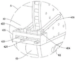
FIG. 1 is a schematic view of the overall structure of the present invention;
FIG. 2 is an enlarged view of the structure at A in FIG. 1 according to the present invention;
FIG. 3 is an enlarged view of the structure at B in FIG. 1 according to the present invention;
FIG. 4 is a schematic side view of the present invention;
FIG. 5 is a partial cross-sectional view of an elevational structure of the invention;
FIG. 6 is an enlarged view of the structure at C in FIG. 5 according to the present invention.
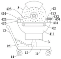
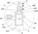
Description of the drawings: 1. a support mechanism; 11. a base; 12. a jack; 121. an operating lever; 122. a connecting rod; 13. a push-pull rod; 14. a universal wheel; 2. a detection device; 3. supporting the box body; 31. a chute; 32. a threaded shaft; 33. a turntable; 4. a first detection mechanism; 41. detecting the shell; 411. a side plate; 412. a base plate; 42. a disk surface detection assembly; 421. a first fixed block; 422. a through groove; 423. a slide bar; 424. a slider; 425. an operating handle; 426. a detection lever; 427. a first eddy current sensor; 43. a periphery detection assembly; 431. a second fixed block; 432. a threaded rod; 433. a second eddy current sensor; 434. a knob; 5. a second detection mechanism; 6. a drive assembly; 61. a roller; 62. a belt pulley; 63. a servo motor; 7. a spacing adjustment assembly; 71. a clamping block; 8. a brake disc; 9. an eddy current detector.
Detailed Description
The following description is merely exemplary in nature and is not intended to limit the present disclosure, application, or uses. It should be understood that throughout the drawings, identical or similar reference numerals indicate identical or similar parts and features. The drawings are only schematic representations of the concepts and principles of the embodiments of the disclosure, not necessarily to scale, showing specific dimensions and proportions of the various embodiments of the disclosure. Certain features that are part of a particular figure may be exaggerated in order to illustrate relevant details or structures of embodiments of the present disclosure.
Referring to fig. 1-6, a brake disc eddy current testing machine comprises a supporting mechanism 1, wherein the supporting mechanism 1 is composed of a base 11 and jacks 12 fixed on the surface of the base 11, a testing device 2 is assembled on the tops of the plungers in the jacks 12, two jacks 12 are arranged, operating rods 121 are rotatably connected to pump cylinders connected with the two jacks 12, the other ends of the two operating rods 121 are fixedly connected with each other through a connecting rod 122 horizontally arranged, a push-pull rod 13 is hinged on the surface of the base 11, the middle part of the push-pull rod 13 is hinged with the middle part of the connecting rod 122, a handle is fixed on the top of the push-pull rod 13, universal wheels 14 are fixed at four corners of the bottom of the base 11, when a car is driven to a repair shop to test a brake disc 8, the car is lifted up through a lifting platform of the repair shop, then, only four tires of the automobile are dismounted, the four brake discs 8 are exposed, at this time, the push-pull rod 13 is pushed, the detection device 2 in the eddy current testing machine is moved to the position below the two front wheels, then the push-pull rod 13 is pressed down to drive the connecting rod 122 to be pressed down, the two operating rods 121 are pressed down, and then plungers in the two jacks 12 are jacked up, so that the detection device 2 can reach the position of the brake discs 8 to be detected, and meanwhile, the eddy current testing machine is convenient to move through the arrangement of the universal wheels 14, so that the eddy current testing machine can be easily moved to the positions of the two rear wheels to be detected after the detection of the two front wheels is finished.
As shown in fig. 1, the detecting device 2 is composed of a supporting box 3, a first detecting mechanism 4 and a second detecting mechanism 5, the eddy current detecting instrument 9 is installed in the supporting box 3, it is worth mentioning that the working principle of the eddy current detecting instrument 9 is a known technology, and not described herein too much, the first detecting mechanism 4 is fixedly installed on the top of the supporting box 3, the first detecting mechanism 4 includes a detecting housing 41, the detecting housing 41 is formed by welding two vertically placed side plates 411 and a bottom plate 412, and the top of the two side plates 411 is assembled with a disk surface detecting assembly 42 and an outer periphery detecting assembly 43, a brake disk 8 is arranged between the disk surface detecting assembly 42 and the outer periphery detecting assembly 43, the disk surface detecting assembly 42 includes a first fixing block, a through groove 422 is formed on the surface of the first fixing block 421, a slide rod 423 is fixed in the through groove 422, and two sliders 424 are slidably connected to the surface of the slide rod 423, the two sliders 424 are both in an L-shaped structure, an operating handle 425 is fixed at the shorter end of each slider 424, the operating handle 425 protrudes out of the through groove 422, the longer end of each slider 424 protrudes out of the through groove 422, a rotating shaft is rotatably connected to the longer end of each slider 424, not shown in the figures, a detection rod 426 is fixed on the surface of each rotating shaft, it should be noted that the friction factor between each rotating shaft and the end of each slider 424 is large, so that the detection rod 426 cannot deflect under the action of gravity after rotating for a certain angle, the periphery of the brake disc 8 is located between the two detection rods 426, a plurality of first eddy current sensors 427 are fixed on one side of each detection rod 426, which is opposite to the disc surface of the brake disc 8, the plurality of first eddy current sensors 427 are electrically connected with the eddy current detector 9 through a conducting wire, the length of each detection rod 426 is not smaller than the radius of the brake disc 8, and therefore, by rotating the two detection rods 426, the end parts of the two detection rods 426 can be respectively close to the circle center positions of the two side surfaces of the brake disc 8, so that when the brake disc 8 rotates, the detection signals of the disc surface of the brake disc 8 can be completely collected by the first eddy current sensors 427, the detection signals are transmitted to the eddy current detector 9 through a lead for analysis and processing, when cracks exist in the disc surface of the brake disc 8, the eddy current detector 9 can give an alarm to prompt, so that a maintenance worker can timely position the cracks of the brake disc 8 to repair the brake disc.
Furthermore, as shown in fig. 1, by adjusting two operation handles 425 by shifting, the detection distance from the first eddy current sensor 427 to the disc surface of the brake disc 8 meets the detection standard, so that the eddy current detection accuracy of the brake disc 8 can be improved, it should be noted that the friction factor between the slider 424 and the slide rod 423 is large, and therefore, after the operation handles 425 are adjusted, the slider 424 does not slide relatively on the surface of the slide rod 423.
Further, as shown in fig. 1 and 4, the periphery detecting assembly 43 includes a second fixing block 431 and a threaded rod 432, the threaded rod 432 penetrates through two sides of the second fixing block 431 and is in threaded connection with the second fixing block 431, one end of the threaded rod 432 close to the periphery of the brake disc 8 is fixed with a second eddy current sensor 433, the second eddy current sensor 433 is electrically connected with the eddy current detector 9 through a wire, the other end of the threaded rod 432 is fixed with a knob 434, and by rotating the knob 434, the detection distance from the second eddy current sensor 433 to the periphery of the brake disc 8 meets the standard, so that the purpose of detecting the periphery of the brake disc 8 by eddy current is achieved.
Install in first detection mechanism 4 and be used for driving rotatory drive assembly 6 of brake disc 8, drive assembly 6 includes servo motor 63 and two roller bearings 61, the surface of two roller bearings 61 is all fixed with the rubber pad, and the periphery of brake disc 8 offsets with the surface of two roller bearings 61, the both ends of roller bearing 61 rotate with two curb plates 411 respectively and are connected, and one end of two roller bearings 61 all runs through one of them curb plate 411 and is fixed with belt pulley 62 respectively, the surface of two belt pulley 62 is through the belt linkage, the other end of one of them roller bearing 61 runs through another curb plate 411 and is connected with servo motor 63's output fixed connection, servo motor 63 installs in the backup pad that is fixed in another curb plate 411 surface, through starting servo motor 63, make servo motor 63's output drive roller bearing 61 rotate, and through the linkage effect of belt, make another roller bearing 61 rotate, and then under the effect of friction, make brake disc 8 rotate, and then realize first eddy current sensor 427 and second eddy current sensor 433 to the all-round eddy current detection purpose of disc 8, namely wide to the detection area of brake disc 8, avoided detecting the brake disc 8 local position and the condition can be favorable to the improvement of the detection precision.
The second detection mechanism 5 is movably installed on the top of the supporting box 3, the second detection mechanism 5 is arranged in parallel with the first detection mechanism 4, that is, the second detection mechanism 5 is also formed by welding two vertically placed side plates 411 and a bottom plate 412, and meanwhile, a disc surface detection assembly 42 and a periphery detection assembly 43 are also assembled in the second detection mechanism 5, as shown in fig. 1, since the second detection mechanism 5 and the first detection mechanism 4 have the same structure, the repeated description is not provided herein, and considering that in order to perform eddy current detection on automobile brake discs 8 with different axial distances, a spacing adjustment assembly 7 for adjusting the spacing between the first detection mechanism 4 and the second detection mechanism 5 is installed in the second detection mechanism 5, the spacing adjustment assembly 7 comprises three clamping blocks 71 which are fixed at the bottom of the bottom plate 412 in the second detection mechanism 5 and are arranged in parallel, three chutes 31 arranged in parallel with each other along the length direction of the support box 3 are formed in the top surface of the support box 3, a threaded shaft 32 is connected in the middle chute 31 in a rotating manner, as shown in fig. 5, the end part of the threaded shaft 32 penetrates through the side wall of the support box 3 and is fixed with a turntable 33, three fixture blocks 71 are respectively connected in the three chutes 31 in a sliding manner, one fixture block 71 in the middle is in threaded connection with the threaded shaft 32, the threaded shaft 32 is driven to rotate by rotating the turntable 33, the fixture block 71 in the middle is moved in the chute 31, so that the distance between the first detection mechanism 4 and the second detection mechanism 5 is adjusted, eddy current detection can be conveniently carried out on the brake discs 8 of automobiles with different axial distances, the brake discs 8 do not need to be detached, and the detection efficiency of an automobile repair factory on the brake discs 8 is effectively improved.
The working principle is as follows: in an automobile repair shop, firstly, a lifter is used for lifting an automobile, the automobile is hung on a neutral gear, tires are dismounted, brake discs 8 are exposed, at the moment, a push-pull rod 13 is pushed to move an eddy current detector below two front wheel brake discs 8, a rotary disc 33 is rotated, the distance between a first detection mechanism 4 and a second detection mechanism 5 is adjusted to enable the first detection mechanism 4 and the second detection mechanism 5 to be respectively aligned with the two front wheel brake discs 8, then the push-pull rod 13 is pressed down to drive a connecting rod 122 to be pressed down, two operating rods 121 are pressed down, and then plungers in two jacks 12 are jacked up, so that the first detection mechanism 4 and the second detection mechanism 5 can reach the positions of the two brake discs 8 until the periphery of one of the front wheel brake discs 8 can be abutted against a rolling shaft 61;
next, the two operation handles 425 in the first detection mechanism 4 and the second detection mechanism 5 are respectively shifted, so that the detection space between the first eddy current sensor 427 and the disc surface of the brake disc 8 meets the detection standard, it should be noted that, considering that the brake discs 8 of different types are different in material, the required detection space is also different, because the detection space between the first eddy current sensor 427 and the brake disc 8 is the existing open technology, that is, the detection standard belongs to known data, which is not described herein too much, the distance between the first eddy current sensor 427 and the brake disc 8 can be controlled by adjusting the distance between the two operation handles 425, and then the knobs 434 in the first detection mechanism 4 and the second detection mechanism 5 are respectively rotated, so that the detection space between the second eddy current sensor 433 and the periphery of the brake disc 8 meets the standard;
then the servo motor 63 is started, the output end of the servo motor 63 drives the rolling shafts 61 to rotate, and the other rolling shaft 61 is driven to rotate through the linkage action of the belt, so that one front wheel brake disc 8 is driven to rotate under the action of friction force, and the other front wheel brake disc 8 is driven to rotate under the action of the neutral gear of the automobile, so that the purpose of omnibearing eddy current detection of the two front wheel brake discs 8 by the first eddy current sensor 427 and the second eddy current sensor 433 in the first detection mechanism 4 and the second detection mechanism 5 is achieved;
and after the eddy current detection of the two front wheel brake discs 8 is finished, moving the eddy current detector to the rear wheel, and repeating the operation until all four brake discs 8 of the automobile are detected.
Exemplary embodiments of the proposed solution of the present disclosure have been described in detail above with reference to preferred embodiments, however, it will be understood by those skilled in the art that many variations and modifications may be made to the specific embodiments described above, and that many combinations of the various technical features and structures presented in the present disclosure may be made without departing from the concept of the present disclosure, without departing from the scope of the present disclosure, which is defined by the appended claims.
Claims (5)
1. The brake disc eddy current testing machine comprises a supporting mechanism (1), wherein the supporting mechanism (1) mainly comprises a base (11) and a jack (12) fixed on the surface of the base (11), and is characterized in that a detection device (2) is assembled at the top of a plunger in the jack (12), the detection device (2) mainly comprises a supporting box body (3), a first detection mechanism (4) and a second detection mechanism (5), an eddy current tester (9) is installed in the supporting box body (3), the first detection mechanism (4) is fixedly installed at the top of the supporting box body (3), the second detection mechanism (5) is movably installed at the top of the supporting box body (3), the second detection mechanism (5) is structurally identical to and arranged in parallel with the first detection mechanism (4), the first detection mechanism (4) comprises a detection shell (41), the detection shell (41) is formed by welding two vertically placed disc surfaces (411) and a bottom plate (412), the top of the two side plates (411) and the periphery detection component (42) and the periphery detection component (43), the detection component (421) is assembled with a fixed block (8), the surface of the first fixing block (421) is provided with a through groove (422), a sliding rod (423) is fixed in the through groove (422), the surface of the sliding rod (423) is connected with two sliding blocks (424) in a sliding manner, the tops of the two sliding blocks (424) are connected with detection rods (426) in a rotating manner, the periphery of the brake disc (8) is positioned between the two detection rods (426), one side, opposite to the disc surface of the brake disc (8), of the two detection rods (426) is fixed with a plurality of first eddy current sensors (427), the first eddy current sensors (427) are electrically connected with an eddy current detector (9) through wires, a driving component (6) for driving the brake disc (8) to rotate is installed in the first detection mechanism (4), drive assembly (6) are including servo motor (63) and two roller bearing (61), two the surface of roller bearing (61) all is fixed with the rubber pad, just the periphery of brake disc (8) offsets with the surface of two roller bearing (61), the both ends of roller bearing (61) are rotated with two curb plates (411) respectively and are connected, and two the one end of roller bearing (61) all runs through one of them curb plate (411) and is fixed with belt pulley (62) respectively, two the surface of belt pulley (62) passes through the belt linkage, one of them the other end of roller bearing (61) runs through another curb plate (411) and with the output of servo motor (63) output Fixed connection, servo motor (63) are installed in the backup pad on another curb plate (411) surface, install interval adjusting part (7) that are used for adjusting first detection mechanism (4) and second detection mechanism (5) interval in second detection mechanism (5), interval adjusting part (7) are including fixing fixture block (71) that three side by side that sets up bottom plate (412) bottom in second detection mechanism (5), three spout (31) along supporting box (3) length direction mutual parallel arrangement have been seted up to the top surface of supporting box (3), are in middle one the spout (31) internal rotation is connected with screw shaft (32), the tip of screw shaft (32) runs through the lateral wall of supporting box (3) and is fixed with carousel (33), and is three fixture block (71) sliding connection respectively is in three spout (31), and is in middle one fixture block (71) and screw shaft (32) threaded connection.
2. The eddy current testing machine for brake discs as defined in claim 1, wherein the outer circumference testing assembly (43) comprises a second fixing block (431) and a threaded rod (432), the threaded rod (432) penetrates through two sides of the second fixing block (431) and is in threaded connection with the second fixing block (431), a second eddy current sensor (433) is fixed at one end of the threaded rod (432) close to the outer circumference of the brake disc (8), the second eddy current sensor (433) is electrically connected with the eddy current tester (9) through a wire, and a knob (434) is fixed at the other end of the threaded rod (432).
3. The brake disc eddy current testing machine according to claim 1, wherein the two sliding blocks (424) are both in an L-shaped structure, an operating handle (425) is fixed at the shorter end of each sliding block (424), the operating handle (425) protrudes out of the through groove (422), the longer end of each sliding block (424) protrudes out of the through groove (422) and is rotatably connected with the detection rod (426), and the length of the detection rod (426) is not less than the radius of the brake disc (8).
4. The brake disc eddy current testing machine according to claim 1, wherein two jacks (12) are provided, the pump cylinders connected with the two jacks (12) are rotatably connected with operating rods (121), the other ends of the two operating rods (121) are fixedly connected with each other through a connecting rod (122) horizontally placed, a push-pull rod (13) is hinged to the surface of the base (11), the middle of the push-pull rod (13) is hinged to the middle of the connecting rod (122), and a handle is fixed to the top of the push-pull rod (13).
5. The brake disc eddy current testing machine according to claim 4, wherein universal wheels (14) are fixed at four corners of the bottom of the base (11).
Priority Applications (1)
| Application Number | Priority Date | Filing Date | Title |
|---|---|---|---|
| CN202211086539.4A CN115166028B (en) | 2022-09-07 | 2022-09-07 | Brake disc eddy current testing machine |
Applications Claiming Priority (1)
| Application Number | Priority Date | Filing Date | Title |
|---|---|---|---|
| CN202211086539.4A CN115166028B (en) | 2022-09-07 | 2022-09-07 | Brake disc eddy current testing machine |
Publications (2)
| Publication Number | Publication Date |
|---|---|
| CN115166028A CN115166028A (en) | 2022-10-11 |
| CN115166028B true CN115166028B (en) | 2022-11-22 |
Family
ID=83481147
Family Applications (1)
| Application Number | Title | Priority Date | Filing Date |
|---|---|---|---|
| CN202211086539.4A Active CN115166028B (en) | 2022-09-07 | 2022-09-07 | Brake disc eddy current testing machine |
Country Status (1)
| Country | Link |
|---|---|
| CN (1) | CN115166028B (en) |
Families Citing this family (1)
| Publication number | Priority date | Publication date | Assignee | Title |
|---|---|---|---|---|
| CN117092209B (en) * | 2023-10-16 | 2023-12-26 | 山东瑞诚智能制造有限公司 | Vortex detection device for brake disc cracks |
Family Cites Families (6)
| Publication number | Priority date | Publication date | Assignee | Title |
|---|---|---|---|---|
| DE202011103105U1 (en) * | 2011-07-12 | 2012-10-22 | Prozeq Sa | Device for determining the state of wear of a carbon-ceramic brake disk |
| CN104076090B (en) * | 2014-07-16 | 2016-06-29 | 北京新联铁科技股份有限公司 | A kind of parallel lifting non-pulling wheel detecting flaw of wheel machine |
| CN207923783U (en) * | 2018-02-06 | 2018-09-28 | 苏州德斯森电子有限公司 | Brake disc carrying out flaw detection mechanism |
| CN208140067U (en) * | 2018-05-28 | 2018-11-23 | 韦士肯(厦门)智能科技有限公司 | A kind of automobile brake disc intelligent checking system |
| CN216350269U (en) * | 2021-03-31 | 2022-04-19 | 驻马店中鹏汽车部件制造有限公司 | Supporting structure for appearance inspection of automobile parts |
| CN113720905B (en) * | 2021-08-25 | 2022-11-11 | 苏州德斯森电子有限公司 | Brake disc eddy current testing machine |
-
2022
- 2022-09-07 CN CN202211086539.4A patent/CN115166028B/en active Active
Also Published As
| Publication number | Publication date |
|---|---|
| CN115166028A (en) | 2022-10-11 |
Similar Documents
| Publication | Publication Date | Title |
|---|---|---|
| CN109282749B (en) | Hub detection device | |
| CN107860673B (en) | Tire abrasion comprehensive testing machine | |
| CN204575352U (en) | A kind of hand-rail type Simple tyre static rigidity measurement mechanism | |
| CN115166028B (en) | Brake disc eddy current testing machine | |
| CN113588298A (en) | Test system for vehicle steering performance | |
| CN213657795U (en) | Cylindrical part surface roughness detection device | |
| CN111156941B (en) | Vehicle brake block surface full run-out detection device | |
| CN219189938U (en) | Detection tool for metering verification detector | |
| CN211576047U (en) | Thickness detection device for flange processing | |
| CN112344885A (en) | Step shaft flatness detection device and flatness detection method thereof | |
| CN114526703B (en) | Adjustable mechanical part thickness measurement detection device | |
| CN212206598U (en) | Car production is with sample car inspection test rack | |
| CN215114298U (en) | Vertical shaft type impact crusher main shaft processing detection device | |
| CN214503222U (en) | Grinding performance test device for quick grinding wheel | |
| CN213121136U (en) | Bicycle and electric vehicle inflation-free tire knocking-over test device | |
| CN112595202A (en) | Steering connecting shaft position size testing tool | |
| CN114682498A (en) | Bearing saddle detection system | |
| CN112880550B (en) | Auxiliary mechanism for automobile product detection | |
| CN219589607U (en) | Angle measuring instrument | |
| CN220398474U (en) | Printer axle core laser detection machine | |
| CN216012705U (en) | Torsion spring life test equipment | |
| CN114199129B (en) | Automatic step shaft size detection equipment | |
| CN220339336U (en) | Automobile part shell height detection device | |
| CN219899716U (en) | Automatic detection device of straightener | |
| CN219348457U (en) | Tire static loading measuring device |
Legal Events
| Date | Code | Title | Description |
|---|---|---|---|
| PB01 | Publication | ||
| PB01 | Publication | ||
| SE01 | Entry into force of request for substantive examination | ||
| SE01 | Entry into force of request for substantive examination | ||
| GR01 | Patent grant | ||
| GR01 | Patent grant |