CN115057555B - An integrated sewage treatment equipment - Google Patents
An integrated sewage treatment equipment Download PDFInfo
- Publication number
- CN115057555B CN115057555B CN202210881876.6A CN202210881876A CN115057555B CN 115057555 B CN115057555 B CN 115057555B CN 202210881876 A CN202210881876 A CN 202210881876A CN 115057555 B CN115057555 B CN 115057555B
- Authority
- CN
- China
- Prior art keywords
- hollow
- treatment agent
- fixed
- hole
- roller
- Prior art date
- Legal status (The legal status is an assumption and is not a legal conclusion. Google has not performed a legal analysis and makes no representation as to the accuracy of the status listed.)
- Active
Links
- 239000010865 sewage Substances 0.000 title claims abstract description 55
- 238000004140 cleaning Methods 0.000 claims abstract description 12
- 239000003795 chemical substances by application Substances 0.000 claims description 96
- XLYOFNOQVPJJNP-UHFFFAOYSA-N water Substances O XLYOFNOQVPJJNP-UHFFFAOYSA-N 0.000 claims description 87
- 238000003825 pressing Methods 0.000 claims description 10
- 239000007788 liquid Substances 0.000 claims description 9
- 238000001125 extrusion Methods 0.000 claims description 7
- 238000009941 weaving Methods 0.000 claims 4
- 239000013618 particulate matter Substances 0.000 claims 2
- 230000010354 integration Effects 0.000 claims 1
- 239000004753 textile Substances 0.000 abstract description 38
- 239000000835 fiber Substances 0.000 abstract description 15
- 239000012535 impurity Substances 0.000 abstract description 6
- 238000000034 method Methods 0.000 abstract description 5
- 238000001556 precipitation Methods 0.000 description 11
- 238000005507 spraying Methods 0.000 description 6
- 238000010586 diagram Methods 0.000 description 5
- 238000003756 stirring Methods 0.000 description 4
- 238000006243 chemical reaction Methods 0.000 description 3
- 238000005054 agglomeration Methods 0.000 description 2
- 230000002776 aggregation Effects 0.000 description 2
- 230000000903 blocking effect Effects 0.000 description 2
- 230000000994 depressogenic effect Effects 0.000 description 2
- 239000003814 drug Substances 0.000 description 2
- 238000001914 filtration Methods 0.000 description 2
- 239000007921 spray Substances 0.000 description 2
- 206010028347 Muscle twitching Diseases 0.000 description 1
- 230000009286 beneficial effect Effects 0.000 description 1
- 230000036461 convulsion Effects 0.000 description 1
- 230000007812 deficiency Effects 0.000 description 1
- 230000000694 effects Effects 0.000 description 1
- 239000004744 fabric Substances 0.000 description 1
- 238000012423 maintenance Methods 0.000 description 1
- 238000004519 manufacturing process Methods 0.000 description 1
- 239000002245 particle Substances 0.000 description 1
- 238000004062 sedimentation Methods 0.000 description 1
Images





Classifications
-
- C—CHEMISTRY; METALLURGY
- C02—TREATMENT OF WATER, WASTE WATER, SEWAGE, OR SLUDGE
- C02F—TREATMENT OF WATER, WASTE WATER, SEWAGE, OR SLUDGE
- C02F1/00—Treatment of water, waste water, or sewage
-
- B—PERFORMING OPERATIONS; TRANSPORTING
- B01—PHYSICAL OR CHEMICAL PROCESSES OR APPARATUS IN GENERAL
- B01F—MIXING, e.g. DISSOLVING, EMULSIFYING OR DISPERSING
- B01F33/00—Other mixers; Mixing plants; Combinations of mixers
- B01F33/80—Mixing plants; Combinations of mixers
- B01F33/83—Mixing plants specially adapted for mixing in combination with disintegrating operations
-
- B—PERFORMING OPERATIONS; TRANSPORTING
- B01—PHYSICAL OR CHEMICAL PROCESSES OR APPARATUS IN GENERAL
- B01F—MIXING, e.g. DISSOLVING, EMULSIFYING OR DISPERSING
- B01F35/00—Accessories for mixers; Auxiliary operations or auxiliary devices; Parts or details of general application
- B01F35/71—Feed mechanisms
- B01F35/717—Feed mechanisms characterised by the means for feeding the components to the mixer
- B01F35/7179—Feed mechanisms characterised by the means for feeding the components to the mixer using sprayers, nozzles or jets
-
- C—CHEMISTRY; METALLURGY
- C02—TREATMENT OF WATER, WASTE WATER, SEWAGE, OR SLUDGE
- C02F—TREATMENT OF WATER, WASTE WATER, SEWAGE, OR SLUDGE
- C02F1/00—Treatment of water, waste water, or sewage
- C02F1/52—Treatment of water, waste water, or sewage by flocculation or precipitation of suspended impurities
- C02F1/5281—Installations for water purification using chemical agents
-
- B—PERFORMING OPERATIONS; TRANSPORTING
- B01—PHYSICAL OR CHEMICAL PROCESSES OR APPARATUS IN GENERAL
- B01F—MIXING, e.g. DISSOLVING, EMULSIFYING OR DISPERSING
- B01F2101/00—Mixing characterised by the nature of the mixed materials or by the application field
- B01F2101/305—Treatment of water, waste water or sewage
Landscapes
- Chemical & Material Sciences (AREA)
- Chemical Kinetics & Catalysis (AREA)
- Life Sciences & Earth Sciences (AREA)
- Hydrology & Water Resources (AREA)
- Engineering & Computer Science (AREA)
- Environmental & Geological Engineering (AREA)
- Water Supply & Treatment (AREA)
- Organic Chemistry (AREA)
- General Chemical & Material Sciences (AREA)
- Biological Treatment Of Waste Water (AREA)
- Crushing And Pulverization Processes (AREA)
Abstract
Description
技术领域technical field
本发明涉及污水处理技术领域,具体为一种一体化污水处理设备。The invention relates to the technical field of sewage treatment, in particular to an integrated sewage treatment equipment.
背景技术Background technique
污水处理被广泛应用于各个领域,在纺织行业生产过程中需要对纺织布进行清洗,因此产生的纺织污水中会有很多纺织绒毛杂质,在进行污水处理时均需要通过多种过滤方式对纺织污水中所含纺织绒毛杂质进行拦截过滤。Sewage treatment is widely used in various fields. In the production process of the textile industry, textile fabrics need to be cleaned. Therefore, there will be a lot of textile fluff impurities in the textile sewage generated. During sewage treatment, textile sewage needs to be filtered through various filtration methods. The textile fluff impurities contained in the filter are intercepted and filtered.
现有的在对纺织污水进行污水处理过程中,由于纺织污水中存在纺织绒毛,因此会采用滤网孔小的滤网对纺织绒毛进行过滤,但纺织绒毛容易粘黏在滤网上,导致滤网的堵塞,影响污水的过滤效果,因此,我们提出了一种一体化污水处理设备。In the existing process of sewage treatment of textile sewage, due to the presence of textile fluff in the textile sewage, a filter with a small filter mesh is used to filter the textile fluff, but the textile fluff is easy to stick to the filter, causing the filter to The clogging will affect the filtration effect of sewage. Therefore, we propose an integrated sewage treatment equipment.
发明内容Contents of the invention
针对现有技术的不足,本发明提供了一种一体化污水处理设备,解决了上述背景技术中提出的问题。Aiming at the deficiencies of the prior art, the present invention provides an integrated sewage treatment equipment, which solves the problems raised in the background art above.
为实现以上目的,本发明通过以下技术方案予以实现:一种一体化污水处理设备,包括设备主体,所述设备主体内部一侧设置有纺织绒毛清理装置,所述纺织绒毛清理装置包括:In order to achieve the above object, the present invention is achieved through the following technical solutions: an integrated sewage treatment device, including a device main body, a textile fluff cleaning device is provided on one side of the device main body, and the textile fluff cleaning device includes:
回形架,所述回形架固定在设备主体的内部,所述回形架的内壁底部开设有凸齿环槽;A loop frame, the loop frame is fixed inside the main body of the equipment, and the bottom of the inner wall of the loop frame is provided with a convex tooth ring groove;
收集盒,所述收集盒焊接在回形架的一侧;A collection box, the collection box is welded on one side of the clip;
中空通孔钩刺辊,所述中空通孔钩刺辊转动安装在回形架的内壁底部,所述中空通孔钩刺辊的顶部贯穿且转动安装在回形架的内壁顶部,所述中空通孔钩刺辊的顶部设置有用于驱动中空通孔钩刺辊转动的驱动件;Hollow through-hole hook licker-in roller, the hollow through-hole hook licker-in roller is rotatably installed on the bottom of the inner wall of the return frame, the top of the hollow through-hole hook licker-in roller penetrates and is rotatably installed on the inner wall top of the return frame, the hollow The top of the through-hole hook licker-in roller is provided with a driving member for driving the rotation of the hollow through-hole hook licker-in roller;
U形推板,所述U形推板贯穿且滑动安装在中空通孔钩刺辊的外壁上,所述U形推板的底部固定有凸柱,所述U形推板的凸柱与凸齿环槽的内部滑动连接。U-shaped push plate, the U-shaped push plate penetrates and is slidably installed on the outer wall of the hollow through-hole hook licker-in roller, the bottom of the U-shaped push plate is fixed with a boss, and the boss of the U-shaped push plate is connected with the convex Internal sliding connection of the ring gear groove.
优选的,所述中空通孔钩刺辊的外侧固定有钩刺,所述中空通孔钩刺辊的外壁上开设有通孔。Preferably, barbs are fixed on the outside of the hollow through-hole hook licker-in roller, and through holes are opened on the outer wall of the hollow through-hole hook licker-in roller.
优选的,所述设备主体的顶部一侧设置有纺织污水处理剂投放装置,所述纺织污水处理剂投放装置包括:Preferably, the top side of the main body of the equipment is provided with a textile sewage treatment agent dispensing device, and the textile sewage treatment agent dispensing device includes:
混合水处理剂药箱,所述混合水处理剂药箱固定在设备主体的顶部,所述混合水处理剂药箱的右侧固定有液泵;A mixed water treatment agent tank, the mixed water treatment agent tank is fixed on the top of the equipment main body, and a liquid pump is fixed on the right side of the mixed water treatment agent tank;
导管,所述导管的一端固定在液泵的一侧,所述导管的另一端转动安装有塞盖,所述塞盖焊接在中空通孔钩刺辊的内部。Conduit, one end of the conduit is fixed on one side of the liquid pump, and the other end of the conduit is rotatably installed with a plug cover, and the plug cover is welded inside the hollow through-hole hook licker-in roller.
优选的,所述塞盖与导管的连接处设置有防水圈。Preferably, a waterproof ring is provided at the connection between the plug cover and the conduit.
优选的,所述塞盖的上方设置有水处理剂辅助喷动装置,所述水处理剂辅助喷动装置包括:Preferably, an auxiliary spraying device for water treatment agent is provided above the plug cover, and the auxiliary spraying device for water treatment agent includes:
L形挤压杆,所述L形挤压杆固定在设备主体的内壁顶部;L-shaped extruding rods, the L-shaped extruding rods are fixed on the top of the inner wall of the equipment main body;
橡胶中空凸块,所述橡胶中空凸块嵌固在塞盖的顶部;a rubber hollow bump, and the rubber hollow bump is embedded and fixed on the top of the plug cover;
叶片杆,所述叶片杆固定在橡胶中空凸块的内壁顶部。The blade rod is fixed on the top of the inner wall of the rubber hollow protrusion.
优选的,所述L形挤压杆的底部与橡胶中空凸块的顶面接触。Preferably, the bottom of the L-shaped extrusion rod is in contact with the top surface of the rubber hollow bump.
优选的,所述塞盖的下方设置有防颗粒物水处理剂沉淀装置,所述防颗粒物水处理剂沉淀装置包括:Preferably, an anti-particulate water treatment agent precipitation device is provided under the plug cover, and the anti-particulate water treatment agent precipitation device includes:
固定压板,所述固定压板固定在U形推板靠近中空通孔钩刺辊内壁的一侧,所述固定压板与中空通孔钩刺辊的内壁之间通过叉形弹板弹性连接;A fixed pressure plate, the fixed pressure plate is fixed on the side of the U-shaped push plate close to the inner wall of the hollow through-hole hook licker-in roller, and the fixed pressure plate is elastically connected to the inner wall of the hollow through-hole hook licker-in roller through a fork spring plate;
翻动叶,所述翻动叶固定叉形弹板的叉槽之间;Turning leaves, the turning leaves are fixed between the fork grooves of the fork spring plate;
压碎弧块,所述压碎弧块固定在叉形弹板远离固定压板的一侧。The crushing arc block is fixed on the side of the fork spring plate away from the fixed pressing plate.
优选的,所述叉形弹板靠近固定压板的一侧固定有压碎弧块。Preferably, a crushing arc block is fixed on the side of the fork-shaped spring plate close to the fixed platen.
本发明提供了一种一体化污水处理设备。具备以下有益效果:The invention provides an integrated sewage treatment equipment. Has the following beneficial effects:
(1)、本发明通过纺织绒毛清理装置的设置,中空通孔钩刺辊上的钩刺在中空通孔钩刺辊转动过程中,中空通孔钩刺辊上的钩刺会对纺织污水中的绒毛和纤维钩住,从而避免了绒毛和纤维等杂质堵塞过滤网的问题,进而提高了对纺织污水处理的效率;在U形推板的凸柱移动到凸齿环槽的凸出部分时,U形推板会对中空通孔钩刺辊的钩刺钩住绒毛和纤维推动并脱离钩刺收集到收集盒中,从而达到了对纺织污水中绒毛和纤维进行收集的目的。(1), the present invention through the setting of textile fluff cleaning device, the barb on the hollow through-hole hook licker-in roller is in the rotation process of the hollow through-hole hook licker-in roller, the barb on the hollow through-hole hook licker-in roller will be in the textile sewage The fluff and fibers are hooked, thereby avoiding the problem of clogging the filter screen by impurities such as fluff and fibers, thereby improving the efficiency of textile sewage treatment; when the convex column of the U-shaped push plate moves to the protruding part of the convex tooth ring The U-shaped push plate will hook the fluff and fibers on the hooks of the hollow through-hole hook roller to push them away from the hooks and collect them in the collection box, thereby achieving the purpose of collecting the fluff and fibers in the textile sewage.
(2)、本发明通过纺织污水处理剂投放装置的设置,水处理剂药箱内部的混合水处理剂通过导管输送到中空通孔钩刺辊的内部,中空通孔钩刺辊内的混合水处理剂通过中空通孔钩刺辊的通孔排出,混合水处理剂会与污水反应,同时在中空通孔钩刺辊转动时会对混合水处理剂和污水搅拌混合,进而提高了对混合水处理剂与污水反应的效率。(2) In the present invention, through the setting of the textile sewage treatment agent delivery device, the mixed water treatment agent inside the water treatment agent tank is transported to the inside of the hollow through-hole hook licker-in roller through the conduit, and the mixed water in the hollow through-hole hook licker-in roller The treatment agent is discharged through the through hole of the hollow through-hole hook licker-in roller, and the mixed water treatment agent will react with the sewage. The efficiency of the reaction between the treatment agent and the sewage.
(3)、本发明通过水处理剂辅助喷动装置的设置,L形挤压杆对橡胶中空凸块进行挤压,橡胶中空凸块形变并对中空通孔钩刺辊内的混合水处理剂进行挤压,从而使得混合水处理剂从中空通孔钩刺辊喷射出,从而提高了混合水处理剂排出的效率;同时橡胶中空凸块形变时会推动叶片杆向下移动,叶片杆会对中空通孔钩刺辊中的混合水处理剂进行搅动,从而使得混合水处理剂中的颗粒状水处理剂悬浮在混合水处理剂中,从而避免了颗粒状水处理剂出现沉淀的问题。(3) In the present invention, through the setting of the water treatment agent auxiliary spraying device, the L-shaped extrusion rod squeezes the rubber hollow bump, and the rubber hollow bump is deformed and the mixed water treatment agent in the hollow through-hole hook licker-in roller Squeeze, so that the mixed water treatment agent is ejected from the hollow through-hole hook licker-in roller, thereby improving the discharge efficiency of the mixed water treatment agent; at the same time, when the rubber hollow bump deforms, it will push the blade rod to move downward, and the blade rod will The mixed water treatment agent in the hollow through-hole hook licker-in roller is stirred, so that the granular water treatment agent in the mixed water treatment agent is suspended in the mixed water treatment agent, thereby avoiding the problem of precipitation of the granular water treatment agent.
(4)、本发明通过防颗粒物水处理剂沉淀装置的设置,叉形弹板形变并带动混合水处理剂涌向中空通孔钩刺辊的通孔,从而使得悬浮的颗粒状水处理剂可以均匀的从中空通孔钩刺辊的通孔排出,叉形弹板形变时带动翻动叶摆动并对混合水处理剂进行搅动,从而进一步避免了颗粒状水处理剂出现沉淀的问题;通过压碎弧块的设置,使叉形弹板带动压碎弧块对结块较大的颗粒状水处理剂进行压碎,进而从本质上解决结块较大的颗粒状水处理剂堵住中空通孔钩刺辊的通孔的问题。(4) In the present invention, through the setting of the anti-particulate water treatment agent precipitation device, the fork spring plate deforms and drives the mixed water treatment agent to rush to the through hole of the hollow through-hole hook licker-in roller, so that the suspended granular water treatment agent can be It is evenly discharged from the through hole of the hollow through-hole hook licker-in roller. When the fork-shaped spring plate is deformed, it drives the turning blade to swing and stir the mixed water treatment agent, thereby further avoiding the problem of sedimentation of the granular water treatment agent; through crushing The setting of the arc block makes the fork-shaped spring plate drive the crushing arc block to crush the agglomerated granular water treatment agent, thereby essentially solving the problem of blocking the hollow through hole by the agglomerated granular water treatment agent The problem of the through hole of the licker-in roller.
附图说明Description of drawings
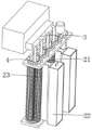
图1为本发明整体的示意图;Fig. 1 is the overall schematic diagram of the present invention;
图2为本发明整体的局部剖面示意图;Fig. 2 is a schematic partial sectional view of the whole of the present invention;
图3为本发明整体的局部结构示意图;Fig. 3 is a schematic diagram of the overall partial structure of the present invention;
图4为本发明纺织绒毛清理装置的局部剖面示意图;Fig. 4 is a schematic partial sectional view of a textile fluff cleaning device of the present invention;
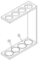
图5为本发明回形架的局部剖面示意图;Fig. 5 is a schematic partial sectional view of a clip frame of the present invention;
图6为本发明纺织污水处理剂投放装置的示意图;Fig. 6 is a schematic diagram of the textile sewage treatment agent delivery device of the present invention;
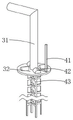
图7为本发明水处理剂辅助喷动装置的示意图;7 is a schematic diagram of the water treatment agent auxiliary spraying device of the present invention;
图8为本发明防颗粒物水处理剂沉淀装置的示意图。Fig. 8 is a schematic diagram of the anti-particulate water treatment agent precipitation device of the present invention.
图中:1、设备主体;2、纺织绒毛清理装置;21、回形架;22、收集盒;23、中空通孔钩刺辊;24、U形推板;25、凸齿环槽;3、纺织污水处理剂投放装置;31、混合水处理剂药箱;32、导管;33、塞盖;4、水处理剂辅助喷动装置;41、L形挤压杆;42、橡胶中空凸块;43、叶片杆;5、防颗粒物水处理剂沉淀装置;51、固定压板;52、叉形弹板;53、翻动叶;54、压碎弧块。In the figure: 1. Equipment main body; 2. Textile fluff cleaning device; 21. Return frame; 22. Collection box; 23. Hollow through-hole hook licker-in roller; 24. U-shaped push plate; 25. Convex tooth ring groove; 3 , Spraying device for textile sewage treatment agent; 31. Mixed water treatment agent tank; 32. Conduit; 33. Plug cover; 4. Auxiliary spraying device for water treatment agent; 41. L-shaped extrusion rod; 42. Rubber
具体实施方式Detailed ways
下面将结合本发明实施例中的附图,对本发明实施例中的技术方案进行清楚、完整地描述,显然,所描述的实施例仅仅是本发明一部分实施例,而不是全部的实施例。The following will clearly and completely describe the technical solutions in the embodiments of the present invention with reference to the accompanying drawings in the embodiments of the present invention. Obviously, the described embodiments are only some, not all, embodiments of the present invention.
请参阅图1-8,本发明提供了一种技术方案:一种一体化污水处理设备,包括设备主体1,设备主体1的内部通过螺栓可拆卸安装有滤网孔小的滤网,通过螺栓安装滤网的方式,使得滤网便于拆卸维护,设备主体1左侧和右侧分别焊接有污水进口管和污水出口管,设备主体1内部靠近污水进口管的一侧设置有纺织绒毛清理装置2,纺织绒毛清理装置2包括:Please refer to Figures 1-8, the present invention provides a technical solution: an integrated sewage treatment equipment, including the equipment main body 1, the interior of the equipment main body 1 is detachably installed with a filter screen with small filter holes through bolts, The way of installing the filter screen makes the filter screen easy to disassemble and maintain. The left side and the right side of the equipment main body 1 are respectively welded with sewage inlet pipes and sewage outlet pipes. The side of the equipment main body 1 close to the sewage inlet pipe is equipped with a textile fluff cleaning device 2 , textile fluff cleaning device 2 comprises:
回形架21,回形架21通过螺栓固定安装在设备主体1的内部,通过螺栓安装回形架21的方式,使得回形架21便于拆卸维护,回形架21的内壁底部开设有四个凸齿环槽25,且两个凸齿环槽25为一组,每组的凸齿环槽25的凸出部分为相对设置,凸齿环槽25用于对U形推板24的移动轨迹进行限制;Back-shaped
收集盒22,收集盒22有两个,两个收集盒22均焊接在回形架21靠近污水出口管的一侧,两个收集盒22分别位于每组的凸齿环槽25之间,收集盒22用于对中空通孔钩刺辊23脱离的绒毛和纤维进行收集;Collecting
中空通孔钩刺辊23,中空通孔钩刺辊23有四个,四个中空通孔钩刺辊23均转动安装在回形架21的内壁底部,四个中空通孔钩刺辊23的顶部均贯穿且转动安装在回形架21的内壁顶部,四个中空通孔钩刺辊23的顶部均固定有齿轮环,且相邻的齿轮环相互啮合,位于中空通孔钩刺辊23一侧的齿轮环通过外接电机驱动,中空通孔钩刺辊23的外侧焊接有若干个钩刺,中空通孔钩刺辊23上的钩刺会对纺织污水中的绒毛和纤维钩住,从而避免了绒毛和纤维等杂质堵塞过滤网的问题,相邻中空通孔钩刺辊23的钩刺为交错设置,中空通孔钩刺辊23位于相邻竖向钩刺之间的外壁开设有通孔,中空通孔钩刺辊23的通孔用于排出混合水处理剂;Hollow through-hole hook licker-in
U形推板24,U形推板24有若干个,若干个U形推板24均贯穿且滑动安装在中空通孔钩刺辊23的外壁上,U形推板24套接在中空通孔钩刺辊23竖向设置的钩刺外侧,U形推板24会对中空通孔钩刺辊23的钩刺钩住绒毛和纤维推动并脱离钩刺,U形推板24的底部焊接有凸柱,U形推板24的凸柱与凸齿环槽25的内部滑动连接,U形推板24的凸柱用于与凸齿环槽25配合带动U形推板24移动。
设备主体1的顶部左侧设置有纺织污水处理剂投放装置3,纺织污水处理剂投放装置3包括:The top left side of the equipment main body 1 is provided with a textile sewage treatment
混合水处理剂药箱31,混合水处理剂药箱31通过螺栓固定安装在设备主体1的顶部,通过螺栓安装混合水处理剂药箱31的方式,便于混合水处理剂药箱31拆卸维护,混合水处理剂药箱31的右侧通过螺栓固定有液泵,液泵用于抽动混合水处理剂药箱31内部的混合水处理剂输出送到中空通孔钩刺辊23内部;The mixed water
导管32,导管32的一端固定在液泵的输出端,导管32的另一端转动安装有塞盖33,导管32用于对混合水处理剂进行导流,塞盖33焊接在中空通孔钩刺辊23的内部,塞盖33与导管32的连接处设置有防水圈,通过防水圈的设置,避免了塞盖33与导管32的连接处出现混合水处理剂泄露的问题。
塞盖33的上方设置有水处理剂辅助喷动装置4,水处理剂辅助喷动装置4包括:The top of the
L形挤压杆41,L形挤压杆41焊接在设备主体1的内壁顶部;L-shaped
橡胶中空凸块42,橡胶中空凸块42有四个,四个橡胶中空凸块42均嵌固在塞盖33的顶部,L形挤压杆41的底部与橡胶中空凸块42的顶面接触,L形挤压杆41对橡胶中空凸块42进行挤压,橡胶中空凸块42向下凹陷形变,橡胶中空凸块42对中空通孔钩刺辊23内的混合水处理剂进行挤压,从而使得混合水处理剂从中空通孔钩刺辊23喷射出,从而提高了混合水处理剂排出的效率;Rubber
叶片杆43,叶片杆43有四个,四个叶片杆43分别固定在四个橡胶中空凸块42的内壁顶部,叶片杆43位于中空通孔钩刺辊23的内部,叶片杆43会对中空通孔钩刺辊23中的混合水处理剂进行搅动。
塞盖33的下方设置有防颗粒物水处理剂沉淀装置5,防颗粒物水处理剂沉淀装置5包括:The bottom of the
固定压板51,固定压板51焊接在U形推板24靠近中空通孔钩刺辊23圆心的一侧,固定压板51与中空通孔钩刺辊23的内壁之间通过两个叉形弹板52弹性连接,且两个叉形弹板52隆起部分为相向设置,固定压板51对叉形弹板52进行挤压,叉形弹板52形变时带动混合水处理剂涌向中空通孔钩刺辊23的通孔,从而使得悬浮的颗粒状水处理剂可以均匀的从中空通孔钩刺辊23的通孔排出;Fixed pressing
翻动叶53,翻动叶53有若干个,若干个翻动叶53分别固定叉形弹板52的叉槽之间,叉形弹板52形变时带动翻动叶53摆动并对混合水处理剂进行搅动,从而进一步避免了颗粒状水处理剂出现沉淀的问题;Turning leaves 53, there are several turning leaves 53, several turning leaves 53 are respectively fixed between the fork grooves of the
压碎弧块54,压碎弧块54有两个,两个压碎弧块54分别焊接在两个叉形弹板52的相向一侧,且两个压碎弧块54位于叉形弹板52远离固定压板51的一侧,通过压碎弧块54的设置,叉形弹板52带动压碎弧块54对结块较大的颗粒状水处理剂进行压碎,进而从本质上解决结块较大的颗粒状水处理剂堵住中空通孔钩刺辊23的通孔的问题。There are two crushing arc blocks 54, and the two crushing arc blocks 54 are respectively welded on opposite sides of the two
使用时,将纺织污水通过污水进口管输送到设备主体1的内部,通过外接电机驱动齿轮环转动,齿轮环带动中空通孔钩刺辊23朝向收集盒22的方向转动,中空通孔钩刺辊23上的钩刺在中空通孔钩刺辊23转动过程中,污水流经中空通孔钩刺辊23时,中空通孔钩刺辊23上的钩刺会对纺织污水中的绒毛和纤维钩住,从而避免了绒毛和纤维等杂质堵塞过滤网的问题,进而提高了对纺织污水处理的效率;中空通孔钩刺辊23带动U形推板24转动,同时U形推板24的凸柱同步移动并沿着凸齿环槽25的内部滑动,在U形推板24的凸柱移动到凸齿环槽25的凸出部分时,U形推板24的凸柱带动U形推板24沿着中空通孔钩刺辊23的钩刺向远离中空通孔钩刺辊23圆心的方向移动,U形推板24会对中空通孔钩刺辊23的钩刺钩住绒毛和纤维推动并脱离钩刺,脱离的绒毛和纤维会随着污水水流落入到收集盒22中,从而达到了对纺织污水中绒毛和纤维进行收集的目的。During use, the textile sewage is transported to the inside of the equipment main body 1 through the sewage inlet pipe, and the gear ring is driven by an external motor to rotate. The gear ring drives the hollow through-hole hook licker-in
同时启动混合水处理剂药箱31的液泵,液泵抽动混合水处理剂药箱31内部的混合水处理剂通过导管32输送到中空通孔钩刺辊23的内部,当U形推板24向远离中空通孔钩刺辊23圆心的方向移动时,U形推板24不再堵住中空通孔钩刺辊23的通孔,中空通孔钩刺辊23内的混合水处理剂通过中空通孔钩刺辊23的通孔排出,混合水处理剂会与污水反应,同时在中空通孔钩刺辊23转动时会对混合水处理剂和污水搅拌混合,进而提高了对混合水处理剂与污水反应的效率。Simultaneously start the liquid pump of the mixed water treatment
中空通孔钩刺辊23带动塞盖33同步转动,中空通孔钩刺辊23带动塞盖33移动到L形挤压杆41处时,L形挤压杆41对橡胶中空凸块42进行挤压,橡胶中空凸块42向下凹陷形变,橡胶中空凸块42对中空通孔钩刺辊23内的混合水处理剂进行挤压,从而使得混合水处理剂从中空通孔钩刺辊23喷射出,从而提高了混合水处理剂排出的效率;同时橡胶中空凸块42形变时会推动叶片杆43向下移动,叶片杆43会对中空通孔钩刺辊23中的混合水处理剂进行搅动,从而使得混合水处理剂中的颗粒状水处理剂悬浮在混合水处理剂中,从而避免了颗粒状水处理剂出现沉淀的问题。The hollow through-hole hook licker-in
当U形推板24向远离中空通孔钩刺辊23圆心的方向移动时,U形推板24带动固定压板51同步移动,固定压板51对叉形弹板52进行挤压,叉形弹板52形变时带动混合水处理剂涌向中空通孔钩刺辊23的通孔,从而使得悬浮的颗粒状水处理剂可以均匀的从中空通孔钩刺辊23的通孔排出;叉形弹板52形变时带动翻动叶53摆动并对混合水处理剂进行搅动,从而进一步避免了颗粒状水处理剂出现沉淀的问题;通过压碎弧块54的设置,压碎弧块54会对水处理剂中结块较大的颗粒状水处理剂进行阻挡,从而避免了结块较大的颗粒状水处理剂堵住中空通孔钩刺辊23的通孔的问题,在U形推板24复位时,叉形弹板52同步复位,叉形弹板52带动压碎弧块54对结块较大的颗粒状水处理剂进行压碎,进而从本质上解决结块较大的颗粒状水处理剂堵住中空通孔钩刺辊23的通孔的问题。When the
以上所述,仅为本发明较佳的具体实施方式,但本发明的保护范围并不局限于此,任何熟悉本技术领域的技术人员在本发明揭露的技术范围内,根据本发明的技术方案及其发明构思加以等同替换或改变,都应涵盖在本发明的保护范围之内。The above is only a preferred embodiment of the present invention, but the scope of protection of the present invention is not limited thereto, any person familiar with the technical field within the technical scope disclosed in the present invention, according to the technical solution of the present invention Any equivalent replacement or change of the inventive concepts thereof shall fall within the protection scope of the present invention.
Claims (6)
Priority Applications (1)
| Application Number | Priority Date | Filing Date | Title |
|---|---|---|---|
| CN202210881876.6A CN115057555B (en) | 2022-07-26 | 2022-07-26 | An integrated sewage treatment equipment |
Applications Claiming Priority (1)
| Application Number | Priority Date | Filing Date | Title |
|---|---|---|---|
| CN202210881876.6A CN115057555B (en) | 2022-07-26 | 2022-07-26 | An integrated sewage treatment equipment |
Publications (2)
| Publication Number | Publication Date |
|---|---|
| CN115057555A CN115057555A (en) | 2022-09-16 |
| CN115057555B true CN115057555B (en) | 2022-11-04 |
Family
ID=83206622
Family Applications (1)
| Application Number | Title | Priority Date | Filing Date |
|---|---|---|---|
| CN202210881876.6A Active CN115057555B (en) | 2022-07-26 | 2022-07-26 | An integrated sewage treatment equipment |
Country Status (1)
| Country | Link |
|---|---|
| CN (1) | CN115057555B (en) |
Families Citing this family (2)
| Publication number | Priority date | Publication date | Assignee | Title |
|---|---|---|---|---|
| CN116022978B (en) * | 2023-03-22 | 2023-08-01 | 深圳永清水务有限责任公司 | System for high-efficient removal of hardness and silicon of iron and steel waste water |
| CN116655152A (en) * | 2023-06-05 | 2023-08-29 | 重庆工商大学 | A kind of sewage treatment method |
Citations (7)
| Publication number | Priority date | Publication date | Assignee | Title |
|---|---|---|---|---|
| JPH09220190A (en) * | 1996-02-16 | 1997-08-26 | Nobuyuki Shiokawa | Roller-type cleaner using adhesive tape |
| US7461664B1 (en) * | 2003-06-25 | 2008-12-09 | Collin Budron | Roller cover end plug |
| CN208678854U (en) * | 2018-05-08 | 2019-04-02 | 上海道多生物科技有限公司 | A kind of chemical proportioner of hydro powered |
| WO2019079951A1 (en) * | 2017-10-23 | 2019-05-02 | 盐城德正机械有限公司 | Novel textile machine frame |
| CN113402042A (en) * | 2021-06-22 | 2021-09-17 | 娄迎旦 | Ultrafiltration separation equipment |
| CN214709899U (en) * | 2021-05-31 | 2021-11-16 | 龙岩市农业科学研究所 | Movable pesticide spraying equipment for pest control |
| CN114191867A (en) * | 2021-11-23 | 2022-03-18 | 浙江求寔新材料股份有限公司 | Printing and dyeing wastewater treatment device |
-
2022
- 2022-07-26 CN CN202210881876.6A patent/CN115057555B/en active Active
Patent Citations (7)
| Publication number | Priority date | Publication date | Assignee | Title |
|---|---|---|---|---|
| JPH09220190A (en) * | 1996-02-16 | 1997-08-26 | Nobuyuki Shiokawa | Roller-type cleaner using adhesive tape |
| US7461664B1 (en) * | 2003-06-25 | 2008-12-09 | Collin Budron | Roller cover end plug |
| WO2019079951A1 (en) * | 2017-10-23 | 2019-05-02 | 盐城德正机械有限公司 | Novel textile machine frame |
| CN208678854U (en) * | 2018-05-08 | 2019-04-02 | 上海道多生物科技有限公司 | A kind of chemical proportioner of hydro powered |
| CN214709899U (en) * | 2021-05-31 | 2021-11-16 | 龙岩市农业科学研究所 | Movable pesticide spraying equipment for pest control |
| CN113402042A (en) * | 2021-06-22 | 2021-09-17 | 娄迎旦 | Ultrafiltration separation equipment |
| CN114191867A (en) * | 2021-11-23 | 2022-03-18 | 浙江求寔新材料股份有限公司 | Printing and dyeing wastewater treatment device |
Also Published As
| Publication number | Publication date |
|---|---|
| CN115057555A (en) | 2022-09-16 |
Similar Documents
| Publication | Publication Date | Title |
|---|---|---|
| CN204034360U (en) | Fill rinsing type ore pulp filter press | |
| CN208378456U (en) | Sewage-treatment plant is used in a kind of processing of fabrics printing and dyeing | |
| CN211536774U (en) | A desilting device for industrial wastewater treatment | |
| CN207012625U (en) | A kind of plate and frame filter press | |
| CN115057555A (en) | Integrated sewage treatment equipment | |
| CN118949607A (en) | Ecological concrete's apparatus for producing | |
| CN117585882A (en) | Belt filter press for sludge dewatering | |
| CN116966658A (en) | Belt filter press for sludge and sewage treatment | |
| CN117861758A (en) | Waste residue collection device is used in zirconium dioxide production | |
| CN211753088U (en) | Water purification structure for water treatment | |
| CN112110608A (en) | High-efficient effluent treatment plant | |
| CN206660687U (en) | A kind of filter-pressing device | |
| CN211611882U (en) | Automatic flushing device for filter cloth of belt filter | |
| CN212609608U (en) | High-efficient scarfing cinder grid machine | |
| CN115417562B (en) | Device for recycling and purifying construction sewage | |
| CN205907063U (en) | Membrane grid high pressure rinse -system | |
| CN210097105U (en) | A grid machine for efficiently cleaning garbage | |
| CN214597481U (en) | A liquid cosmetic semi-finished product filter device | |
| CN213563760U (en) | Plastic raw material settling cask | |
| CN215654657U (en) | Flue gas treatment equipment for chemical production | |
| CN116869174A (en) | Fresh ginger mud removing and cleaning device for agricultural product processing | |
| CN115318001A (en) | Cycle reuse informatization full-automatic water filter | |
| CN208406200U (en) | A kind of cleaning device of filter press | |
| CN108160609B (en) | Cleaning device of part cleaning machine | |
| CN213555749U (en) | Internal inflow fine grid device |
Legal Events
| Date | Code | Title | Description |
|---|---|---|---|
| PB01 | Publication | ||
| PB01 | Publication | ||
| SE01 | Entry into force of request for substantive examination | ||
| SE01 | Entry into force of request for substantive examination | ||
| GR01 | Patent grant | ||
| GR01 | Patent grant | ||
| TR01 | Transfer of patent right | ||
| TR01 | Transfer of patent right |
Effective date of registration: 20241011 Address after: 716000 Liuquzi Purified Water Plant, Wuqi County, Yan'an City, Shaanxi Province Patentee after: Shaanxi Water Group Wuqi County Sewage Treatment Co.,Ltd. Country or region after: China Address before: No. 1609, Taihua Building, Qingzhou City, Weifang City, Shandong Province, 261000 Patentee before: Shandong Zhide Environmental Engineering Co.,Ltd. Country or region before: China |