CN115014165A - Length detection device for needle production inspection - Google Patents
Length detection device for needle production inspection Download PDFInfo
- Publication number
- CN115014165A CN115014165A CN202210952836.6A CN202210952836A CN115014165A CN 115014165 A CN115014165 A CN 115014165A CN 202210952836 A CN202210952836 A CN 202210952836A CN 115014165 A CN115014165 A CN 115014165A
- Authority
- CN
- China
- Prior art keywords
- groove
- wall
- clamping
- needle
- rubber
- Prior art date
- Legal status (The legal status is an assumption and is not a legal conclusion. Google has not performed a legal analysis and makes no representation as to the accuracy of the status listed.)
- Granted
Links
- 238000007689 inspection Methods 0.000 title claims abstract description 20
- 238000001514 detection method Methods 0.000 title claims abstract description 19
- 238000004519 manufacturing process Methods 0.000 title claims abstract description 19
- 210000000078 claw Anatomy 0.000 claims description 38
- 238000001179 sorption measurement Methods 0.000 claims description 19
- 238000003780 insertion Methods 0.000 claims description 13
- 230000037431 insertion Effects 0.000 claims description 13
- 230000003247 decreasing effect Effects 0.000 claims description 4
- 238000005259 measurement Methods 0.000 abstract description 5
- 238000011179 visual inspection Methods 0.000 description 5
- 238000001035 drying Methods 0.000 description 3
- 238000002347 injection Methods 0.000 description 3
- 239000007924 injection Substances 0.000 description 3
- 238000000034 method Methods 0.000 description 3
- 238000005070 sampling Methods 0.000 description 3
- 238000004506 ultrasonic cleaning Methods 0.000 description 3
- 229910000831 Steel Inorganic materials 0.000 description 2
- 238000005520 cutting process Methods 0.000 description 2
- 230000000694 effects Effects 0.000 description 2
- 238000009434 installation Methods 0.000 description 2
- 230000000149 penetrating effect Effects 0.000 description 2
- 239000000243 solution Substances 0.000 description 2
- 239000010959 steel Substances 0.000 description 2
- 230000002159 abnormal effect Effects 0.000 description 1
- 230000009286 beneficial effect Effects 0.000 description 1
- 230000000903 blocking effect Effects 0.000 description 1
- 238000004140 cleaning Methods 0.000 description 1
- 238000010586 diagram Methods 0.000 description 1
- 238000006073 displacement reaction Methods 0.000 description 1
- 239000003292 glue Substances 0.000 description 1
- 238000010438 heat treatment Methods 0.000 description 1
- 238000010030 laminating Methods 0.000 description 1
- 239000007788 liquid Substances 0.000 description 1
- 210000003205 muscle Anatomy 0.000 description 1
- 229920002545 silicone oil Polymers 0.000 description 1
- 238000007920 subcutaneous administration Methods 0.000 description 1
- 210000003462 vein Anatomy 0.000 description 1
Images


Classifications
-
- G—PHYSICS
- G01—MEASURING; TESTING
- G01B—MEASURING LENGTH, THICKNESS OR SIMILAR LINEAR DIMENSIONS; MEASURING ANGLES; MEASURING AREAS; MEASURING IRREGULARITIES OF SURFACES OR CONTOURS
- G01B5/00—Measuring arrangements characterised by the use of mechanical techniques
- G01B5/02—Measuring arrangements characterised by the use of mechanical techniques for measuring length, width or thickness
-
- G—PHYSICS
- G01—MEASURING; TESTING
- G01B—MEASURING LENGTH, THICKNESS OR SIMILAR LINEAR DIMENSIONS; MEASURING ANGLES; MEASURING AREAS; MEASURING IRREGULARITIES OF SURFACES OR CONTOURS
- G01B3/00—Measuring instruments characterised by the use of mechanical techniques
- G01B3/20—Slide gauges
-
- G—PHYSICS
- G01—MEASURING; TESTING
- G01B—MEASURING LENGTH, THICKNESS OR SIMILAR LINEAR DIMENSIONS; MEASURING ANGLES; MEASURING AREAS; MEASURING IRREGULARITIES OF SURFACES OR CONTOURS
- G01B5/00—Measuring arrangements characterised by the use of mechanical techniques
- G01B5/0002—Arrangements for supporting, fixing or guiding the measuring instrument or the object to be measured
Abstract
The invention discloses a length detection device for needle production inspection, which relates to the technical field of length detection and comprises a vernier caliper and a support component, wherein the support component comprises a clamping unit, a clamping unit and a connecting unit, and the clamping unit comprises a rubber turntable, a clamping groove and an inserting groove. The device can realize horizontal limiting clamping of the needle to be detected by arranging the clamping unit, can realize clamping of the needle with different diameters by the clamping grooves with different diameters and the rotatable rubber turntables, can be convenient for the clamping unit and the vernier to be installed and fixed by the clamping unit and the connecting unit, is simple and convenient to operate, can enable the needle to be detected to be in a horizontal state when being measured by the device through the matching of the plurality of parts, has accurate measurement data, can effectively release two hands of a detector through the clamping limitation of the clamping unit on the needle to be detected, can enable the detector to better operate a vernier caliper, and further improves the working efficiency of needle detection.
Description
Technical Field
The invention relates to the technical field of length detection, in particular to a length detection device for needle head production inspection.
Background
The injection needle is composed of needle seat, needle head and protecting sleeve, and is mainly suitable for injection in skin, subcutaneous, muscle and vein of human body or for extracting medicinal liquid.
The production process flow of the traditional injection needle is as follows: seamless steel pipe → heating and drawing pipe → cutting pipe → first visual inspection → ultrasonic cleaning → drying → arranging and pasting glue and fixing → grinding needle point → second visual inspection → high pressure cleaning → inspecting (removing) burr → whole bundle → ultrasonic cleaning → inspecting and blocking → inspecting burr → re-ultrasonic cleaning → drying → pasting needle → drying → silicone oil → covering, the pipe cutting process is to cut the thin steel pipe into a specified length, the first visual inspection is to detect the length of the cut needle head, the grinding needle point is to grind the needle point part of the needle head to a required angle, the second visual inspection is to detect the length and the needle point angle of the ground needle head, so as to ensure the yield of the product, and in the actual production process, the detected product is required to be subjected to a sampling inspection operation to verify whether the visual inspection equipment is normal or not, to eliminate abnormal situations, and in the sampling inspection of the needle head, the length of the needle is generally measured and checked by a vernier caliper, but the vernier caliper has the following problems when the length of the needle is measured:
the contact area between the two ends of the small-diameter needle head and the two inner measuring claws of the vernier caliper is small, so that the needle head is measured in an inclined state easily in the measuring process, and the accuracy of measured data is influenced;
therefore, in order to improve the accuracy of needle sampling inspection, a length detection device for needle production inspection is provided.
Disclosure of Invention
The invention aims to: in order to solve the problem that measuring error easily appears when traditional slide caliper carries out length detection to the syringe needle, provide a syringe needle production length detection device for inspection.
In order to achieve the purpose, the invention provides the following technical scheme: a length detection device for needle head production inspection comprises a vernier caliper, wherein the vernier caliper is composed of a main ruler, a vernier, a movable inner measuring claw and a fixed inner measuring claw, the fixed inner measuring claw is fixed at one end of the bottom end of the main ruler, the vernier is connected to the outer side of the main ruler in a sliding mode, the movable inner measuring claw is fixed at one end of the bottom end of the vernier, a T-shaped groove is formed in one side of the outer wall of the vernier, a supporting component for auxiliary supporting of needle heads to be detected is arranged on one side of the outer wall of the vernier, and the supporting component comprises a clamping unit for clamping the needle heads of different models, a clamping unit for connecting the clamping unit with the vernier and a connecting unit for providing mounting support for the clamping unit;
the clamping unit comprises a rubber turntable, clamping grooves and insertion grooves, the clamping grooves are formed in one end of the outer wall of the rubber turntable and penetrate through the other end of the rubber turntable, the insertion grooves penetrate through the outer side of the rubber turntable from one side of the inner wall of each clamping groove, the clamping grooves are arranged in a plurality of numbers, the clamping grooves are arranged in a mode that the circle centers of the rubber turntable serve as the center, the inner wall diameters of the clamping grooves are uniformly distributed in an annular mode, the inner wall diameters of the clamping grooves are gradually decreased, and the inner wall diameters of the clamping grooves are matched with the outer diameter of the needle head to be detected.
As a still further scheme of the invention: the number of the inserting grooves is matched with that of the clamping grooves and corresponds to that of the clamping grooves one by one, and the widths of the inner walls of the inserting grooves are sequentially decreased progressively and are smaller than the diameters of the inner walls of the inserting grooves.
As a still further scheme of the invention: the outer wall track of the rubber rotary table is in a vortex line structure, and the maximum radius line of the rubber rotary table coincides with the center point of the clamping groove with the maximum diameter.
As a still further scheme of the invention: the engaging unit includes:
the vernier caliper is characterized by comprising a connecting seat arranged on one side of the outer wall of a vernier, wherein one side of the outer wall of the connecting seat is fixedly connected with a T-shaped seat which is sleeved with a fixed inner measuring claw, and the other side of the outer wall of the connecting seat is fixedly connected with two fixed sleeves;
rotate to be connected in the inboard axis of rotation of two fixed sleeves, the one end of axis of rotation extends to the outside one end of connecting seat, just the outer wall connection of axis of rotation has adsorption block, spacing fixture block is located the one end of connecting seat, the adsorption block is located between two fixed sleeves.
As a still further scheme of the invention: the length of connecting seat and the length phase-match of vernier, the outer wall size and the T type inslot wall size phase-match of T type seat.
As a still further scheme of the invention: when the adsorption block is in a vertical state and is attached to the connecting seat, the spacing clamping block and the connecting seat are in a vertical state, and a magnetic adsorption block is embedded in one side, close to the connecting seat, of the adsorption block.
As a still further scheme of the invention: the connection unit includes:
the connecting arm is fixedly connected to one end of the rotating shaft and is positioned at one end, far away from the connecting seat, of the limiting clamping block;
the two supporting seats are fixedly connected to one side of the outer wall of the connecting arm and close to the bottom end, and are symmetrically distributed and internally provided with rotating grooves;
the rubber rotary disc is positioned in the middle of the two supporting seats and is sleeved outside the polygonal rotary column, the clamping groove which is farthest away from the connecting arm is positioned under the main scale and is positioned between the movable inner measuring claw and the fixed inner measuring claw, and a polygonal hole groove matched with the outer wall of the polygonal rotary column is formed in the position where the rubber rotary disc is contacted with the polygonal rotary column.
As a still further scheme of the invention: the inside of supporting seat is provided with and is used for rotating the locating component who carries out the location to polygon rotary column, locating component includes:
the telescopic ball is arranged in the polygonal rotating column and penetrates into the rotating groove, and the polygonal rotating column is internally provided with a telescopic groove matched with the diameter of the outer wall of the telescopic ball;
and the telescopic spring is arranged in the telescopic groove and is positioned on one side of the telescopic ball.
As a still further scheme of the invention: the number of the telescopic balls is four, every two of the telescopic balls are in a group, one group of the telescopic balls are horizontally and symmetrically distributed, the other group of the telescopic balls are vertically and symmetrically distributed, and the number of the edges of the outer wall of the polygonal rotating column is matched with the number of the clamping grooves and corresponds to the number of the outer wall of the polygonal rotating column one by one.
Compared with the prior art, the invention has the beneficial effects that:
can realize the spacing centre gripping of the level of the syringe needle that awaits measuring through setting up the centre gripping unit, through the centre gripping groove of different diameters size and can pivoted rubber carousel, can realize the syringe needle centre gripping of different diameters size, can be convenient for centre gripping unit and vernier to install fixedly through block unit and linkage unit, the operation is simple, and is convenient, cooperation through above a plurality of parts can make the syringe needle that awaits measuring be in the horizontality when being surveyed, its measured data is accurate, and it is spacing to the centre gripping of the syringe needle that awaits measuring through the centre gripping unit, can effectively release detection personnel's both hands, make it can better operate vernier caliper, then further improvement the work efficiency that the syringe needle detected.
Drawings
FIG. 1 is a schematic structural view of the present invention;
FIG. 2 is a schematic view of the backside structure of the present invention;
FIG. 3 is a schematic view of the cursor structure according to the present invention;
FIG. 4 is a schematic structural view of the support assembly of the present invention;
FIG. 5 is a schematic view of the connection between the connecting base and the T-shaped base and the fixing sleeve of the present invention;
FIG. 6 is a schematic view of the connection between the rotating shaft and the adsorbing block and between the rotating shaft and the limiting block;
FIG. 7 is a schematic view of the connection unit and the clamping unit according to the present invention;
FIG. 8 is a sectional view of the internal structure of the support base according to the present invention;
FIG. 9 is a schematic view of the connection between the rubber turntable and the polygonal rotary column according to the present invention;
FIG. 10 is a schematic structural diagram of a rubber turntable according to the present invention;
fig. 11 is a cross-sectional view of a rubber turntable of the present invention.
In the figure: 1. a vernier caliper; 101. a main scale; 102. a cursor; 103. a movable inner measuring jaw; 104. fixing an inner measuring claw; 105. a T-shaped groove;
2. a support assembly; 201. a clamping unit; 202. a connection unit; 203. a clamping unit;
2011. a connecting seat; 2012. a T-shaped seat; 2013. fixing the sleeve; 2014. a rotating shaft; 2015. an adsorption block; 2016. a limiting clamping block;
2021. a connecting arm; 2022. a supporting seat; 2023. a polygonal rotating column; 2024. a rotating groove;
2031. a rubber turntable; 2032. a clamping groove; 2033. inserting grooves; 2034. a polygonal hole groove;
3. a positioning assembly; 301. a telescopic ball; 302. a telescoping spring.
Detailed Description
The technical solutions in the embodiments of the present invention will be clearly and completely described below with reference to the drawings in the embodiments of the present invention, and it is obvious that the described embodiments are only a part of the embodiments of the present invention, and not all of the embodiments. All other embodiments, which can be derived by a person skilled in the art from the embodiments given herein without making any creative effort, shall fall within the protection scope of the present invention.
In the description of the present invention, it should be noted that the terms "center", "upper", "lower", "left", "right", "vertical", "horizontal", "inner", "outer", etc., indicate orientations or positional relationships based on the orientations or positional relationships shown in the drawings, and are only for convenience of description and simplicity of description, but do not indicate or imply that the device or element being referred to must have a particular orientation, be constructed and operated in a particular orientation, and thus, should not be construed as limiting the present invention. Furthermore, the terms "first," "second," and "third" are used for descriptive purposes only and are not to be construed as indicating or implying relative importance. In the description of the present invention, it should be noted that, unless otherwise explicitly specified or limited, the terms "mounted," "connected," and "disposed" are to be construed broadly, e.g., as meaning either a fixed connection, a removable connection, or an integral connection; can be mechanically or electrically connected; they may be connected directly or indirectly through intervening media, or they may be interconnected between two elements. The specific meanings of the above terms in the present invention can be understood in specific cases to those skilled in the art. The following describes an embodiment of the present invention based on its overall structure.
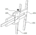
Referring to fig. 1 to 11, in an embodiment of the present invention, a length detection device for needle production inspection includes a vernier caliper 1, where the vernier caliper 1 is composed of a main ruler 101, a vernier 102, a movable inner measuring claw 103 and a fixed inner measuring claw 104, the fixed inner measuring claw 104 is fixed at one end of the bottom end of the main ruler 101, the vernier 102 is slidably connected to the outer side of the main ruler 101, the movable inner measuring claw 103 is fixed at one end of the bottom end of the vernier 102, a T-shaped groove 105 is formed in one side of an outer wall of the vernier 102, a support assembly 2 for auxiliary supporting a needle to be detected is disposed on one side of the outer wall of the vernier 102, and the support assembly 2 includes a clamping unit 203 for clamping different types of needles, a clamping unit 201 for connecting the clamping unit 203 with the vernier 102, and a connection unit 202 for providing mounting support for the clamping unit 203;
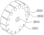
wherein, the clamping unit 203 includes rubber turntable 2031, clamping groove 2032 and inserting groove 2033, clamping groove 2032 is seted up in rubber turntable 2031's outer wall one end and is run through to rubber turntable 2031's the other end, inserting groove 2033 runs through to rubber turntable 2031's the outside from clamping groove 2032's inner wall one side, clamping groove 2032's quantity is provided with a plurality ofly, a plurality of clamping groove 2032 use the centre of a circle of rubber turntable 2031 to be the inner wall diameter that annular evenly distributed and a plurality of clamping groove 2032 degressive in proper order as the center, and clamping groove 2032's inner wall diameter and the external diameter phase-match of the syringe needle that awaits measuring.
In this embodiment, when the needle length is measured, the vernier 102 may be pulled to move away from the fixed inner measuring claw 104 by a distance, the distance is longer than the length of the needle to be measured, and then the whole supporting component 2 is connected with the vernier 102 through the engaging unit 201, so that the rubber turntable 2031 is located between the fixed inner measuring claw 104 and the movable inner measuring claw 103, wherein the center line of one clamping groove 2032 may coincide with the fixed inner measuring claw 104 and the movable inner measuring claw 103, and at this time, the rubber turntable 2031 may be rotated, so that the clamping groove 2032 matched with the diameter of the needle to be measured rotates to the fixed inner measuring claw 104 and the movable inner measuring claw 103, and at this time, the needle to be measured may be mounted inside the clamping groove 2032, and in this process, the mounting may be performed by two methods:
firstly, a needle to be measured is longitudinally inserted into the clamping groove 2032 from one end of the rubber turntable 2031 and passes through the clamping groove 2032, and one end of the needle to be measured is attached to the inner side of the movable inner measuring claw 103;
secondly, the needle to be measured is transversely aligned to the insertion groove 2033 and is extruded to cause the insertion groove 2033 to be stressed and deformed, so that the needle to be measured can slide into the clamping groove 2032, and then the needle to be measured is moved to enable one end of the needle to be measured to be attached to the inner side of the movable inner measuring claw 103;
after the completion syringe needle installation that awaits measuring, can remove vernier 102 and remove to fixed interior measurement claw 104 direction, thereby make the other end of the syringe needle that awaits measuring and the inboard laminating of fixed interior measurement claw 104, read the length numerical value that the digit is the syringe needle that awaits measuring this moment, can make the syringe needle that awaits measuring be in the horizontality when being surveyed through above operation, its measured data is accurate, and it is spacing to the centre gripping of the syringe needle that awaits measuring through centre gripping unit 203, can effectively release measurement personnel's both hands, make it can better operate vernier caliper 1, then further improvement the work efficiency that the syringe needle detected.
Please refer to fig. 9-11, the number of the plugging grooves 2033 is matched with the number of the clamping grooves 2032 and corresponds to each other, and the widths of the inner walls of the plugging grooves 2033 are decreased gradually and are smaller than the diameter of the inner wall of the plugging groove 2033; the outer wall track of the rubber turntable 2031 is in a spiral line structure, and the maximum radius line of the rubber turntable 2031 coincides with the center point of the clamping groove 2032 with the maximum diameter.
In this embodiment: the needle can be conveniently mounted inside the clamping groove 2032 through the insertion groove 2033, the measurement operation of the needle without the diameter can be adapted through the clamping grooves 2032 with different diameters, because the circle centers of the clamping grooves 2032 are positioned on the same concentric circle track, along with the reduction of the inner diameter of the clamping groove 2032, the depth of the insertion groove 2033 penetrating through the rubber turntable 2031 is increased, the needle mounting with small diameter is not convenient for the excessively deep insertion groove 2033, and therefore, the depth of the insertion groove 2033 corresponding to the clamping grooves 2032 with different diameters can be changed along with the increase of the depth of the insertion groove 2033 through the vortex-shaped outer wall structure of the rubber turntable 2031, and the needle mounting with different diameters can be facilitated by the depth of the insertion grooves 2033.
Referring to fig. 1 to 11, the engaging unit 201 includes a connecting seat 2011 disposed at one side of an outer wall of the cursor 102, a T-shaped seat 2012 sleeved with the fixed inner measuring claw 104 is fixedly connected to one side of the outer wall of the connecting seat 2011, and two fixing sleeves 2013 are fixedly connected to the other side of the outer wall of the connecting seat 2011;
a rotating shaft 2014 connected to the inner sides of the two fixed sleeves 2013 in a rotating mode, one end of the rotating shaft 2014 extends to one end of the outer portion of the connecting seat 2011, an adsorption block 2015 and a limiting clamping block 2016 are connected to the outer wall of the rotating shaft 2014, the limiting clamping block 2016 is located at one end of the connecting seat 2011, and the adsorption block 2015 is located between the two fixed sleeves 2013; the length of the connecting seat 2011 is matched with that of the cursor 102, and the size of the outer wall of the T-shaped seat 2012 is matched with that of the inner wall of the T-shaped groove 105; when the adsorption block 2015 is vertically attached to the connecting seat 2011, the limiting fixture block 2016 is vertically attached to the connecting seat 2011, and a magnetic adsorption block is embedded in one side, close to the connecting seat 2011, of the adsorption block 2015;
the connecting unit 202 comprises a connecting arm 2021 fixedly connected to one end of the rotating shaft 2014, and the connecting arm 2021 is located at one end of the limiting clamping block 2016 away from the connecting seat 2011;
the two supporting seats 2022 are fixedly connected to one side of the outer wall of the connecting arm 2021 near the bottom end, the two supporting seats 2022 are symmetrically distributed, and a rotating groove 2024 is formed in the two supporting seats 2022;
the polygonal rotating column 2023 is rotatably connected to the inside of the rotating groove 2024 and penetrates to the two ends of the outside of the supporting seat 2022, the rubber turntable 2031 is located in the middle of the two supporting seats 2022 and is sleeved on the outside of the polygonal rotating column 2023, the clamping groove 2032 which is farthest away from the connecting arm 2021 is located right below the main ruler 101 and is located between the movable inner measuring claw 103 and the fixed inner measuring claw 104, and a polygonal hole 2034 matched with the outer wall of the polygonal rotating column 2023 is formed at the position where the rubber turntable 2031 contacts with the polygonal rotating column 2023.
In this embodiment: when the supporting component 2 needs to be installed, the rotation axis 2014 can be firstly rotated to enable the adsorption block 2015 and the connecting seat 2011 to be separated and to be in a 90-degree vertical state, at the moment, the limiting fixture block 2016 can synchronously rotate to be in a vertical state to be parallel to the connecting seat 2011, then the T-shaped seat 2012 and the T-shaped groove 105 are aligned and completely inserted into the T-shaped groove 105, at the moment, one side of the connecting seat 2011 is attached to the cursor 102, two ends of the connecting seat 2011 are aligned to two ends of the cursor 102, then the rotation axis 2014 is reversely rotated, the magnetic adsorption block on the side surface of the adsorption block 2015 is attached to the surface of the connecting seat 2011, the rotation axis 2014 can be fixed by being adsorbed on the connecting seat 2011 through the suction force of the magnetic adsorption block, meanwhile, the limiting fixture block 2016 can synchronously rotate to be in a state vertical to the connecting seat 2011 and the cursor 102, at the moment, relative displacement in the X-axis direction cannot be carried out between the connecting seat 2011 and the cursor 102, and the Y2012 of the T-shaped groove 105 is matched, Spacing of Z axle direction, realized promptly that connecting seat 2011 and vernier 102's is connected fixedly, a centre gripping groove 2032 of rubber carousel 2031 this moment is located between measuring claw 103 and the fixed interior measuring claw 104 in the activity, can be convenient for measure the fixed spacing of syringe needle that awaits measuring between measuring claw 103 and the fixed interior measuring claw 104 in the activity through this structure, and make the syringe needle that awaits measuring keep the horizontality, so that measured data keeps good precision, can be convenient for rubber carousel 2031 and polygon pivot 2023 to install through multilateral hole groove 2034, and can not take place dislocation phenomenon when making rubber carousel 2031 rotate between the polygon pivot 2023, can provide the support for rubber carousel 2031's rotation through polygon pivot 2023.
Please refer to fig. 7-8, a positioning assembly 3 for positioning the rotation of the polygonal rotating post 2023 is disposed inside the supporting seat 2022, the positioning assembly 3 includes a telescopic ball 301 disposed inside the polygonal rotating post 2023 and penetrating into the rotating groove 2024, and a telescopic groove matched with the diameter of the outer wall of the telescopic ball 301 is disposed inside the polygonal rotating post 2023;
a telescopic spring 302 arranged in the telescopic groove and positioned at one side of the telescopic ball 301; the number of the telescopic balls 301 is four, two by two sets of the four telescopic balls 301, one set of the telescopic balls 301 is horizontally and symmetrically distributed, the other set of the telescopic balls 301 is vertically and symmetrically distributed, and the number of the outer wall edges of the polygonal rotating column 2023 is matched with the number of the clamping grooves 2032 and corresponds to the number of the outer wall edges of the polygonal rotating column 2032.
In this embodiment: when the rubber turnplate 2031 and the supporting seats 2022 are required to be installed, the rubber turnplate 2031 is placed between the two supporting seats 202, and then the polygonal rotating column 2023 is inserted into the rotating groove 2024 from one end of one supporting seat 2022 and penetrates through the polygonal groove 2034 and the moving groove 2024 of the other supporting seat 2022, so as to complete the installation of the rubber turnplate 2031, at this time, the plurality of retractable balls 301 can limit the polygonal surface of the polygonal rotating column 2023, the corners of the polygonal rotating column 2023 are attached to the inner wall of the rotating groove 2024, when the rubber turnplate 2031 is rotated, the rubber turnplate 1 will drive the polygonal rotating column 2023 to rotate, at this time, the corners of the polygonal rotating column 2023 will squeeze the retractable balls 301, so that the retractable balls 301 move to squeeze the retractable springs 302, thereby facilitating the rotation of the polygonal rotating column 2023, when one corner of the polygonal rotating column 2023 is rotated to separate from the retractable balls 301, the telescopic balls 301 will automatically return under the action of the telescopic springs 302, so as to limit the polygonal rotating column 2023 again, and the rotation positioning of the rubber turntable 2031 can be realized through the matching of the telescopic balls 301, so that one clamping groove 2032 can be kept between the movable inner measuring claw 103 and the fixed inner measuring claw 104.
The above description is only for the preferred embodiment of the present invention, but the scope of the present invention is not limited thereto, and any person skilled in the art should be considered to be within the technical scope of the present invention, and the technical solutions and the inventive concepts thereof according to the present invention are equivalent to or changed within the technical scope of the present invention.
Claims (9)
1. The length detection device for needle production inspection comprises a vernier caliper (1), wherein the vernier caliper (1) consists of a main scale (101), a vernier (102), a movable inner measuring claw (103) and a fixed inner measuring claw (104), and is characterized in that a T-shaped groove (105) is formed in one side of the outer wall of the vernier (102), a support component (2) for auxiliary support of a needle to be detected is arranged on one side of the outer wall of the vernier (102), the support component (2) comprises a clamping unit (203) for clamping needles of different models, a clamping unit (201) for connecting the clamping unit (203) with the vernier (102) and a connecting unit (202) for providing mounting support for the clamping unit (203);
wherein, centre gripping unit (203) includes rubber carousel (2031), centre gripping groove (2032) and inserting groove (2033), the outer wall one end of rubber carousel (2031) is seted up in centre gripping groove (2032) and is run through to the other end of rubber carousel (2031), inserting groove (2033) runs through to the outside of rubber carousel (2031) from the inner wall one side of centre gripping groove (2032), the quantity of centre gripping groove (2032) is provided with a plurality ofly, and is a plurality of centre gripping groove (2032) uses the centre of a circle of rubber carousel (2031) as the center to be the inner wall diameter that annular evenly distributed and a plurality of centre gripping groove (2032) degressive in proper order, just the inner wall diameter of centre gripping groove (2032) and the external diameter phase-match of the syringe needle that awaits measuring.
2. The length detection device for needle head production inspection according to claim 1, wherein the number of the insertion grooves (2033) is matched with the number of the clamping grooves (2032) and corresponds to one another, and the widths of the inner walls of the insertion grooves (2033) are gradually decreased and are smaller than the diameter of the inner wall of the insertion groove (2033).
3. The length detecting device for needle production inspection according to claim 1, wherein the outer wall track of the rubber rotary disc (2031) is in a spiral line structure, and the maximum radius line of the rubber rotary disc (2031) coincides with the center point of the clamping groove (2032) with the maximum diameter.
4. A length detecting device for needle production inspection according to claim 1, wherein the engaging unit (201) comprises:
the measuring device is characterized by comprising a connecting seat (2011) arranged on one side of the outer wall of the cursor (102), a T-shaped seat (2012) sleeved with a fixed inner measuring claw (104) is fixedly connected to one side of the outer wall of the connecting seat (2011), and two fixing sleeves (2013) are fixedly connected to the other side of the outer wall of the connecting seat (2011);
rotate and connect in axis of rotation (2014) of two fixed sleeves (2013) inboards, the one end of axis of rotation (2014) extends to connecting seat (2011) outside one end, just the outer wall connection of axis of rotation (2014) has adsorption block (2015), spacing fixture block (2016) are located the one end of connecting seat (2011), adsorption block (2015) are located between two fixed sleeves (2013).
5. The length detection device for needle head production inspection according to claim 4, wherein the length of the connecting seat (2011) is matched with the length of the cursor (102), and the size of the outer wall of the T-shaped seat (2012) is matched with the size of the inner wall of the T-shaped groove (105).
6. The length detection device for needle head production inspection according to claim 4, wherein when the adsorption block (2015) is in a vertical state and is attached to the connecting seat (2011), the spacing clamping block (2016) and the connecting seat (2011) are in a vertical state, and a magnetic attraction block is embedded in one side of the adsorption block (2015) close to the connecting seat (2011).
7. A length detecting device for needle production inspection according to claim 4, characterized in that the connecting unit (202) comprises:
the connecting arm (2021) is fixedly connected to one end of the rotating shaft (2014), and the connecting arm (2021) is located at one end, far away from the connecting seat (2011), of the limiting clamping block (2016);
the two supporting seats (2022) are fixedly connected to one side of the outer wall of the connecting arm (2021) and are close to the bottom end, the two supporting seats (2022) are symmetrically distributed, and a rotating groove (2024) is formed in each supporting seat;
the rubber rotary table is rotatably connected to the inside of the rotating groove (2024) and penetrates through the polygonal rotating columns (2023) at the two outer ends of the supporting seats (2022), the rubber rotary table (2031) is located in the middle of the two supporting seats (2022) and is sleeved on the outer sides of the polygonal rotating columns (2023), the clamping groove (2032) which is farthest away from the connecting arm (2021) is located right below the main scale (101) and is located between the movable inner measuring claw (103) and the fixed inner measuring claw (104), and the polygonal hole groove (2034) matched with the outer walls of the polygonal rotating columns (2023) is formed in the position where the rubber rotary table (2031) is in contact with the polygonal rotating columns (2023).
8. The length detection device for needle head production inspection according to claim 7, wherein a positioning component (3) for positioning the rotation of the polygonal rotating column (2023) is arranged inside the supporting seat (2022), and the positioning component (3) comprises:
the telescopic ball (301) is arranged inside the polygonal rotating column (2023) and penetrates into the rotating groove (2024), and the inside of the polygonal rotating column (2023) is provided with a telescopic groove matched with the diameter of the outer wall of the telescopic ball (301);
and a telescopic spring (302) which is arranged in the telescopic groove and is positioned at one side of the telescopic ball (301).
9. The length detection device for needle head production inspection according to claim 8, wherein the number of the telescopic balls (301) is four, the four telescopic balls (301) are grouped in pairs, one group of the telescopic balls (301) are horizontally and symmetrically distributed, the other group of the telescopic balls (301) are vertically and symmetrically distributed, and the number of the outer wall edges of the polygonal rotating column (2023) is matched with the number of the clamping grooves (2032) and corresponds to the number of the clamping grooves (2032) one by one.
Priority Applications (1)
| Application Number | Priority Date | Filing Date | Title |
|---|---|---|---|
| CN202210952836.6A CN115014165B (en) | 2022-08-10 | 2022-08-10 | Length detection device for needle production inspection |
Applications Claiming Priority (1)
| Application Number | Priority Date | Filing Date | Title |
|---|---|---|---|
| CN202210952836.6A CN115014165B (en) | 2022-08-10 | 2022-08-10 | Length detection device for needle production inspection |
Publications (2)
| Publication Number | Publication Date |
|---|---|
| CN115014165A true CN115014165A (en) | 2022-09-06 |
| CN115014165B CN115014165B (en) | 2022-11-04 |
Family
ID=83065919
Family Applications (1)
| Application Number | Title | Priority Date | Filing Date |
|---|---|---|---|
| CN202210952836.6A Active CN115014165B (en) | 2022-08-10 | 2022-08-10 | Length detection device for needle production inspection |
Country Status (1)
| Country | Link |
|---|---|
| CN (1) | CN115014165B (en) |
Citations (18)
| Publication number | Priority date | Publication date | Assignee | Title |
|---|---|---|---|---|
| GB2129131A (en) * | 1982-10-27 | 1984-05-10 | Massey Ferguson Perkins Ltd | Caliper gauge |
| US4611404A (en) * | 1983-12-29 | 1986-09-16 | Arsenault Ronald G | Caliper for thread measurement |
| US4731931A (en) * | 1987-03-16 | 1988-03-22 | Andromeda Technology, Inc. | Caliper system |
| JP4113903B1 (en) * | 2007-01-31 | 2008-07-09 | 株式会社ニチリン | Concentricity measuring instrument and concentricity measuring method using the same |
| CN203216402U (en) * | 2013-04-16 | 2013-09-25 | 上海海洋大学 | Vernier caliper for measuring the thickness of irregular object |
| CN206084605U (en) * | 2016-08-26 | 2017-04-12 | 台州群发自动化设备有限公司 | Many station machine of efficient bed |
| CN206479105U (en) * | 2017-02-23 | 2017-09-08 | 苏州建设监理有限公司 | Micrometer |
| CN206818082U (en) * | 2017-06-20 | 2017-12-29 | 李佳霖 | A kind of senior middle school's natural sciences Physical Experiment micrometer caliper |
| CN107708551A (en) * | 2015-04-14 | 2018-02-16 | 半岛骨科(私人)有限公司 | Femoral head measurement apparatus |
| CN207113748U (en) * | 2017-08-08 | 2018-03-16 | 苏州美特精密模具标准件有限公司 | Slide measure subsidiary tool |
| CN209069136U (en) * | 2018-12-30 | 2019-07-05 | 苏州爱科德精密仪器有限公司 | A kind of adjustable gage button outside micrometer |
| CN210220863U (en) * | 2019-08-05 | 2020-03-31 | 苏州市豪威自动化设备有限公司 | Micrometer convenient to operation of taking |
| CN210704022U (en) * | 2019-10-31 | 2020-06-09 | 钱娅琴 | Tip flash removed device is used in aluminum product processing |
| CN211696117U (en) * | 2020-03-27 | 2020-10-16 | 长春市宝成伟业汽车零部件有限公司 | Micrometer |
| CN214255600U (en) * | 2020-12-11 | 2021-09-21 | 广州宇城信息科技有限公司 | Cable fixing structure for LED screen |
| CN214543378U (en) * | 2021-05-13 | 2021-10-29 | 田托 | Categorised fixing device of power cable |
| CN216081202U (en) * | 2021-10-27 | 2022-03-18 | 苏州浩弓精密工业有限公司 | External micrometer with protective structure for detecting part size |
| CN216422356U (en) * | 2021-12-08 | 2022-05-03 | 浙江中航来宝精工科技有限公司 | High assembly efficiency location inserted bar anchor clamps fast switch over device |
-
2022
- 2022-08-10 CN CN202210952836.6A patent/CN115014165B/en active Active
Patent Citations (18)
| Publication number | Priority date | Publication date | Assignee | Title |
|---|---|---|---|---|
| GB2129131A (en) * | 1982-10-27 | 1984-05-10 | Massey Ferguson Perkins Ltd | Caliper gauge |
| US4611404A (en) * | 1983-12-29 | 1986-09-16 | Arsenault Ronald G | Caliper for thread measurement |
| US4731931A (en) * | 1987-03-16 | 1988-03-22 | Andromeda Technology, Inc. | Caliper system |
| JP4113903B1 (en) * | 2007-01-31 | 2008-07-09 | 株式会社ニチリン | Concentricity measuring instrument and concentricity measuring method using the same |
| CN203216402U (en) * | 2013-04-16 | 2013-09-25 | 上海海洋大学 | Vernier caliper for measuring the thickness of irregular object |
| CN107708551A (en) * | 2015-04-14 | 2018-02-16 | 半岛骨科(私人)有限公司 | Femoral head measurement apparatus |
| CN206084605U (en) * | 2016-08-26 | 2017-04-12 | 台州群发自动化设备有限公司 | Many station machine of efficient bed |
| CN206479105U (en) * | 2017-02-23 | 2017-09-08 | 苏州建设监理有限公司 | Micrometer |
| CN206818082U (en) * | 2017-06-20 | 2017-12-29 | 李佳霖 | A kind of senior middle school's natural sciences Physical Experiment micrometer caliper |
| CN207113748U (en) * | 2017-08-08 | 2018-03-16 | 苏州美特精密模具标准件有限公司 | Slide measure subsidiary tool |
| CN209069136U (en) * | 2018-12-30 | 2019-07-05 | 苏州爱科德精密仪器有限公司 | A kind of adjustable gage button outside micrometer |
| CN210220863U (en) * | 2019-08-05 | 2020-03-31 | 苏州市豪威自动化设备有限公司 | Micrometer convenient to operation of taking |
| CN210704022U (en) * | 2019-10-31 | 2020-06-09 | 钱娅琴 | Tip flash removed device is used in aluminum product processing |
| CN211696117U (en) * | 2020-03-27 | 2020-10-16 | 长春市宝成伟业汽车零部件有限公司 | Micrometer |
| CN214255600U (en) * | 2020-12-11 | 2021-09-21 | 广州宇城信息科技有限公司 | Cable fixing structure for LED screen |
| CN214543378U (en) * | 2021-05-13 | 2021-10-29 | 田托 | Categorised fixing device of power cable |
| CN216081202U (en) * | 2021-10-27 | 2022-03-18 | 苏州浩弓精密工业有限公司 | External micrometer with protective structure for detecting part size |
| CN216422356U (en) * | 2021-12-08 | 2022-05-03 | 浙江中航来宝精工科技有限公司 | High assembly efficiency location inserted bar anchor clamps fast switch over device |
Non-Patent Citations (1)
| Title |
|---|
| 刘玉喜: "内孔环槽测量专用卡尺", 《铁道机车车辆工人》 * |
Also Published As
| Publication number | Publication date |
|---|---|
| CN115014165B (en) | 2022-11-04 |
Similar Documents
| Publication | Publication Date | Title |
|---|---|---|
| CN107152922B (en) | A kind of method of on-position measure annular plane form error | |
| CN104714123B (en) | Electrical property detection device | |
| CN104713498A (en) | Three-point-supported automatic rotating angle detection tool | |
| CN115014165B (en) | Length detection device for needle production inspection | |
| CN106017388B (en) | Spider inner hole testing agency | |
| CN209027403U (en) | A kind of novel test device for high technology ceramics | |
| CN205919803U (en) | Spider hole detection mechanism | |
| CN211292414U (en) | Hardness detector | |
| CN220818826U (en) | Gear checking tool | |
| CN219914313U (en) | Flatness gauge for bearing seat of wind power generator | |
| CN117554221B (en) | Tunnel face surrounding rock hardness detection device | |
| CN219580603U (en) | Sample detection device | |
| CN213812106U (en) | Glass bottle vertical axis deviation tester convenient for clamping glass bottle | |
| CN217738079U (en) | Comprehensive checking fixture for size of lower protective pipe | |
| CN220288503U (en) | Roundness measuring instrument in tubular part | |
| CN218916239U (en) | Concrete pole detection test bed | |
| CN220437327U (en) | Coaxiality detection device for valve seat hole and guide pipe hole of cylinder cover | |
| CN209961122U (en) | Chuck spiral line detector | |
| CN216745804U (en) | Radial runout detection equipment for stator part of engine | |
| CN114509007B (en) | Laser measuring equipment for measuring cylindrical products | |
| CN209101956U (en) | High accuracy linear dimension pipe fitting positioning support seat | |
| CN112254692B (en) | Detecting tool for detecting span-ball distance of turbine disc | |
| CN209101940U (en) | High accuracy linear dimension pipe fitting locating and detecting device | |
| CN220292034U (en) | Wireless mouse Bluetooth signal transmission detection device | |
| CN212843273U (en) | Automobile power steering gear shell unloading hole position degree checking fixture |
Legal Events
| Date | Code | Title | Description |
|---|---|---|---|
| PB01 | Publication | ||
| PB01 | Publication | ||
| SE01 | Entry into force of request for substantive examination | ||
| SE01 | Entry into force of request for substantive examination | ||
| GR01 | Patent grant | ||
| GR01 | Patent grant | ||
| PE01 | Entry into force of the registration of the contract for pledge of patent right | ||
| PE01 | Entry into force of the registration of the contract for pledge of patent right |
Denomination of invention: A length detection device for needle production inspection Granted publication date: 20221104 Pledgee: Heze rural commercial bank Limited by Share Ltd. Pledgor: SHANDONG KERUI MEDICAL SUPPLIES Co.,Ltd. Registration number: Y2024980001360 |