CN114986706B - Automatic manufacturing device and method for civil engineering laboratory samples - Google Patents
Automatic manufacturing device and method for civil engineering laboratory samples Download PDFInfo
- Publication number
- CN114986706B CN114986706B CN202210413861.7A CN202210413861A CN114986706B CN 114986706 B CN114986706 B CN 114986706B CN 202210413861 A CN202210413861 A CN 202210413861A CN 114986706 B CN114986706 B CN 114986706B
- Authority
- CN
- China
- Prior art keywords
- steel bar
- platform
- vibrating
- reinforcing steel
- discharging
- Prior art date
- Legal status (The legal status is an assumption and is not a legal conclusion. Google has not performed a legal analysis and makes no representation as to the accuracy of the status listed.)
- Active
Links
Images


Classifications
-
- B—PERFORMING OPERATIONS; TRANSPORTING
- B28—WORKING CEMENT, CLAY, OR STONE
- B28C—PREPARING CLAY; PRODUCING MIXTURES CONTAINING CLAY OR CEMENTITIOUS MATERIAL, e.g. PLASTER
- B28C7/00—Controlling the operation of apparatus for producing mixtures of clay or cement with other substances; Supplying or proportioning the ingredients for mixing clay or cement with other substances; Discharging the mixture
- B28C7/0046—Storage or weighing apparatus for supplying ingredients
- B28C7/0053—Storage containers, e.g. hoppers, silos, bins
-
- B—PERFORMING OPERATIONS; TRANSPORTING
- B28—WORKING CEMENT, CLAY, OR STONE
- B28B—SHAPING CLAY OR OTHER CERAMIC COMPOSITIONS; SHAPING SLAG; SHAPING MIXTURES CONTAINING CEMENTITIOUS MATERIAL, e.g. PLASTER
- B28B1/00—Producing shaped prefabricated articles from the material
- B28B1/04—Producing shaped prefabricated articles from the material by tamping or ramming
- B28B1/045—Producing shaped prefabricated articles from the material by tamping or ramming combined with vibrating or jolting
-
- B—PERFORMING OPERATIONS; TRANSPORTING
- B28—WORKING CEMENT, CLAY, OR STONE
- B28B—SHAPING CLAY OR OTHER CERAMIC COMPOSITIONS; SHAPING SLAG; SHAPING MIXTURES CONTAINING CEMENTITIOUS MATERIAL, e.g. PLASTER
- B28B13/00—Feeding the unshaped material to moulds or apparatus for producing shaped articles; Discharging shaped articles from such moulds or apparatus
- B28B13/02—Feeding the unshaped material to moulds or apparatus for producing shaped articles
-
- B—PERFORMING OPERATIONS; TRANSPORTING
- B28—WORKING CEMENT, CLAY, OR STONE
- B28C—PREPARING CLAY; PRODUCING MIXTURES CONTAINING CLAY OR CEMENTITIOUS MATERIAL, e.g. PLASTER
- B28C5/00—Apparatus or methods for producing mixtures of cement with other substances, e.g. slurries, mortars, porous or fibrous compositions
- B28C5/08—Apparatus or methods for producing mixtures of cement with other substances, e.g. slurries, mortars, porous or fibrous compositions using driven mechanical means affecting the mixing
- B28C5/0806—Details; Accessories
-
- B—PERFORMING OPERATIONS; TRANSPORTING
- B28—WORKING CEMENT, CLAY, OR STONE
- B28C—PREPARING CLAY; PRODUCING MIXTURES CONTAINING CLAY OR CEMENTITIOUS MATERIAL, e.g. PLASTER
- B28C7/00—Controlling the operation of apparatus for producing mixtures of clay or cement with other substances; Supplying or proportioning the ingredients for mixing clay or cement with other substances; Discharging the mixture
- B28C7/04—Supplying or proportioning the ingredients
- B28C7/0404—Proportioning
-
- B—PERFORMING OPERATIONS; TRANSPORTING
- B28—WORKING CEMENT, CLAY, OR STONE
- B28C—PREPARING CLAY; PRODUCING MIXTURES CONTAINING CLAY OR CEMENTITIOUS MATERIAL, e.g. PLASTER
- B28C7/00—Controlling the operation of apparatus for producing mixtures of clay or cement with other substances; Supplying or proportioning the ingredients for mixing clay or cement with other substances; Discharging the mixture
- B28C7/04—Supplying or proportioning the ingredients
- B28C7/06—Supplying the solid ingredients, e.g. by means of endless conveyors or jigging conveyors
-
- B—PERFORMING OPERATIONS; TRANSPORTING
- B28—WORKING CEMENT, CLAY, OR STONE
- B28C—PREPARING CLAY; PRODUCING MIXTURES CONTAINING CLAY OR CEMENTITIOUS MATERIAL, e.g. PLASTER
- B28C7/00—Controlling the operation of apparatus for producing mixtures of clay or cement with other substances; Supplying or proportioning the ingredients for mixing clay or cement with other substances; Discharging the mixture
- B28C7/16—Discharge means, e.g. with intermediate storage of fresh concrete
-
- F—MECHANICAL ENGINEERING; LIGHTING; HEATING; WEAPONS; BLASTING
- F26—DRYING
- F26B—DRYING SOLID MATERIALS OR OBJECTS BY REMOVING LIQUID THEREFROM
- F26B17/00—Machines or apparatus for drying materials in loose, plastic, or fluidised form, e.g. granules, staple fibres, with progressive movement
- F26B17/26—Machines or apparatus for drying materials in loose, plastic, or fluidised form, e.g. granules, staple fibres, with progressive movement with movement performed by reciprocating or oscillating conveyors propelling materials over stationary surfaces; with movement performed by reciprocating or oscillating shelves, sieves, or trays
-
- F—MECHANICAL ENGINEERING; LIGHTING; HEATING; WEAPONS; BLASTING
- F26—DRYING
- F26B—DRYING SOLID MATERIALS OR OBJECTS BY REMOVING LIQUID THEREFROM
- F26B21/00—Arrangements or duct systems, e.g. in combination with pallet boxes, for supplying and controlling air or gases for drying solid materials or objects
- F26B21/004—Nozzle assemblies; Air knives; Air distributors; Blow boxes
-
- F—MECHANICAL ENGINEERING; LIGHTING; HEATING; WEAPONS; BLASTING
- F26—DRYING
- F26B—DRYING SOLID MATERIALS OR OBJECTS BY REMOVING LIQUID THEREFROM
- F26B2200/00—Drying processes and machines for solid materials characterised by the specific requirements of the drying good
- F26B2200/14—Sand
Landscapes
- Engineering & Computer Science (AREA)
- Chemical & Material Sciences (AREA)
- Mechanical Engineering (AREA)
- Dispersion Chemistry (AREA)
- General Engineering & Computer Science (AREA)
- Manufacturing & Machinery (AREA)
- Ceramic Engineering (AREA)
- Structural Engineering (AREA)
- Devices For Post-Treatments, Processing, Supply, Discharge, And Other Processes (AREA)
Abstract
The invention provides an automatic sample manufacturing device for a civil engineering laboratory, which comprises a material cleaning and drying device, a concrete distributing and stirring device, a stirrer cleaning device, a cement pumping and pouring device, a vibrating and laminating device and a reinforcing steel bar bundling device which are sequentially arranged. The invention realizes the cleaning and drying before the concrete stirring, the material-dividing stirring of mixed concrete, and the automatic pouring, trowelling and film coating work of the concrete mold surface after the vibration is completed by utilizing the compression roller and the film clamp, thereby having high efficiency and small manpower consumption; meanwhile, the used stirrer can be cleaned in time, so that the stirring machine is convenient and efficient.
Description
Automatic manufacturing device and method for civil engineering laboratory samples
Technical Field
The invention relates to an automatic manufacturing device and method for a civil engineering laboratory sample.
Background
The existing institutions or scientific research institutions often need to carry out concrete test piece experiments, test piece manufacturing is needed, manual operation is adopted in test piece manufacturing, manual operation is adopted in material cleaning, material distributing and stirring mixing and material vibrating, trowelling and laminating, and time and labor waste and low efficiency are achieved in the operation process for students.
Disclosure of Invention
The invention improves the problems, namely the technical problem to be solved by the invention is to provide an automatic manufacturing device and method for the samples of the civil engineering laboratory, which are convenient and efficient to use.
The invention is composed by that, it includes material cleaning and drying device, concrete material distributing and stirring device, mixer cleaning device, cement pumping pouring mould device, vibrating film device and reinforcing bar binding device which are set up in turn, the vibrating film device includes vibrating table, the vibrating table includes base and vibrating motor fixed above the base, the output shaft of the vibrating motor is fixed with rotary table, the eccentric of the rotary table is connected with a supporting table, the supporting table is used for placing mould, the side of the base is provided with vertical support, the top of the vertical support is hinged with swinging swing bar, the swing bar is hinged with rolling press roller, the back side of the vertical support is also fixed with clamp which can clamp film, the vertical support is driven by support driving device to move transversely, the cement pumping pouring mould device includes pouring device above the vibrating table, the pouring device includes temporary storage tank, the temporary storage tank is connected with negative pressure pipe, the lower part of the temporary storage tank is provided with blanking pipe for discharging material, the negative pressure pipe is provided with electromagnetic valve for controlling the opening and closing of blanking.
Further, a visual camera or a laser sensor is fixed on the temporary storage tank.
Further, the supporting table comprises a lower supporting table and an upper supporting table, wherein the lower supporting table is eccentrically and hinged with the turntable, the upper supporting table is connected with the upper part of the lower supporting table through a spring, a limiting hole is formed in the surface of the upper supporting table, and a limiting rod for limiting a die is inserted into the limiting hole; a film support arranged vertically is fixed on the side of the base, a film conveying roller is hinged on the film support, a film is wound on the film conveying roller, the clamp comprises a pair of clamping plates fixedly connected through bolts, one clamping plate is fixed on the swing rod, and the film is clamped between the two clamping plates; the vertical supports are provided with a pair of swing rods, the two vertical supports are connected through a connecting rod, the pressing roller is hinged to the connecting rod, the length of the pressing roller is consistent with the side length of the corresponding die side, the bottom of each vertical support is fixedly provided with a sliding block, two sides of the base are fixedly provided with guide rails matched with the sliding blocks, the guide rails are matched with the sliding blocks to form an I shape, and the support driving device is a support electric cylinder.
Further, the temporary storage tank is arranged on a manipulator, the manipulator comprises a base and a first motor with a vertical output shaft fixed on the base, the output shaft of the first motor is fixedly connected with a second motor with a longitudinal output shaft, the output shaft of the second motor is fixedly connected with a first swing arm, the upper end of the first swing arm is fixedly provided with a horizontal cross arm which is horizontally arranged, and the end part of the horizontal cross arm is hinged with the temporary storage tank through a bearing.
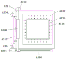
Further, the reinforcing steel bar binding device comprises a hollow rectangular frame, the upper surface of the rectangular frame is uniformly fixed with a reinforcing steel bar fixing seat, the reinforcing steel bar fixing seat comprises a pair of crutch-shaped supports which are arranged in opposite directions, a gap between the longitudinal parts of the crutch-shaped supports forms a gap for falling into reinforcing steel bars, a bottom plate is fixed at the bottom of the rectangular frame, and a motor for driving the rectangular frame to rotate is fixed at the center of the bottom plate.
Further, the lower end of the frame motor is fixed on a sliding seat, the sliding seat is driven by an electric cylinder to horizontally move, a steel bar discharging hopper for storing steel bars is arranged at the side of the upper part of the frame, a steel bar discharging roller for discharging the steel bars is arranged in the middle of the steel bar discharging hopper and is driven by the motor to rotate, grooves for discharging the steel bars are formed in the surface of the steel bar discharging roller at intervals, two sides of the steel bar discharging hopper are close to the surface of the steel bar discharging roller to prevent the steel bars from being separated from the side parts, a discharging opening is formed in the bottom of the steel bar discharging hopper, a sliding rail is arranged below the sliding seat, and the matching surface of the sliding seat and the sliding rail is I-shaped; the vertical portion of turning form support is higher than twice bar diameter, the horizontal portion of turning form support passes through the bolt fastening at rectangular frame upper surface, the horizontal portion of turning form support has the bolt hole that passes for the bolt, rectangular frame upper surface has the channel or the bolt hole that pass for the bolt, and rectangular frame's opposite side fixed bar fixing base symmetry sets up.
Further, the material cleaning and drying device comprises a first vibrating mesh screen, an upper flushing head and a lower flushing head which are arranged on a first side part above and below the first vibrating mesh screen, wherein the upper flushing head and the lower flushing head face the first vibrating mesh screen, a hot air spray head is arranged on a second side part above the first vibrating mesh screen, the hot air spray head faces the first vibrating mesh screen, the first end of the first vibrating mesh screen is higher than the second end, the first end of the first vibrating mesh screen is sequentially connected with a first inclined plate and a first inclined conveyor belt, and the second end of the first vibrating mesh screen is sequentially connected with a second inclined plate and a second inclined conveyor belt; the upper flushing heads and the lower flushing heads are respectively provided with three upper flushing heads which are parallel to each other and form an included angle of 120 degrees with the horizontal plane, and the three lower flushing heads are parallel to each other and form an included angle of-120 degrees with the horizontal plane; a water containing tank is arranged below the first vibration mesh screen, is sequentially connected with a water pipe and a water delivery pump, and is communicated with an upper flushing head and a lower flushing head through pipelines; the upper part of the water containing tank body is provided with a filtering net bag which is in a tank shape, and the side part of the filtering net bag is provided with a hook which is hung on the side wall opening of the water containing tank; the output end of the first inclined conveyor belt is higher than the first end of the first vibrating mesh screen, and meanwhile, the first inclined plate is downwards inclined from the output end of the first inclined conveyor belt and inclines towards the first end of the first vibrating mesh screen; the input end of the second inclined conveyor belt is lower than the second end of the first vibrating mesh screen, and the second inclined plate is downwards inclined from the second end of the first vibrating mesh screen and inclines towards the input end of the second inclined conveyor belt; the output end of the second inclined conveyor belt is communicated with a material tank positioned on the frame; a plurality of material tanks are arranged at the upper part of the frame, a weighing hopper is arranged below each material tank, a stirrer is arranged below each weighing hopper, and a discharging hopper car positioned on a discharging track is arranged below a discharging port of the stirrer; the machine frame comprises a plurality of upright rods, a first platform and a second platform, wherein the upright rods are vertically arranged, the first platform and the second platform are arranged on the upright rods, the second platform is higher than the first platform, the material tank is arranged in a pore canal of the second platform, a funnel is arranged on the first platform, the weighing hopper is fixed on a frame of the first platform, and a lower discharge hole of the weighing hopper is opposite to an upper opening of the funnel; the lower part of the material tank is provided with a material guide channel, and the lower outlet of the material guide channel is opposite to the upper opening of the weighing hopper.
Further, the concrete distributing and stirring device comprises a frame, a plurality of material tanks are arranged on the upper portion of the frame, a weighing hopper is arranged below each material tank, a stirrer is arranged below each weighing hopper, and a discharging hopper car positioned on a discharging track is arranged below a discharging hole of the stirrer; the machine frame comprises a plurality of upright rods, a first platform and a second platform, wherein the upright rods are vertically arranged, the first platform and the second platform are arranged on the upright rods, the second platform is higher than the first platform, the material tank is arranged in a pore canal of the second platform, a funnel is arranged on the first platform, the weighing hopper is fixed on a frame of the first platform, and a lower discharge hole of the weighing hopper is opposite to an upper opening of the funnel; the lower part of the material tank is provided with a material guide channel, and the lower outlet of the material guide channel is opposite to the upper opening of the weighing hopper; the material tank is used for containing various ingredients of civil engineering test concrete, the material tank is in a cylindrical shape, the lower parts of the material tank are provided with control valves, each control valve is connected with a material guide channel, and the lower outlet of the material guide channel is opposite to the upper opening of the corresponding weighing hopper; and weighing sensors are arranged between the first platform and the second platform and the material tank and between the first platform and the weighing hopper so as to realize weighing, and the weighing sensors of the material tank and the weighing hopper are respectively of C3 and C6 grades.
Further, the stirrer cleaning device comprises a linear guide rail positioned at the side part of the stirrer and a guide seat capable of moving along the linear guide rail, a lifting table is arranged above the guide seat, and a high-pressure water gun, a water tank and a water pump are arranged above the lifting table, wherein the high-pressure water gun and the water tank are rotatable, a spray head of the water pump is positioned at an opening part above the stirrer, and the water pump is used for conveying water in the water tank into the high-pressure water gun; the high-pressure water gun comprises a high-pressure water pipe which is in a bent shape or a bent shape, a high-pressure spray head which is positioned above the stirring machine is arranged at the upper end of the high-pressure water pipe, and high-pressure spray nozzles are arranged at the periphery and the bottom of the high-pressure spray head; the bottom of the high-pressure water pipe is provided with a support shaft, a bearing used for penetrating the support shaft is arranged in the lifting platform, and a motor used for driving the support shaft to rotate is arranged in the lifting platform; the high-pressure water pipe is connected with the water pump by a hose; the guide seat is internally provided with an air cylinder for driving the lifting platform to move up and down, and a guide column is arranged between the lifting platform and the guide seat.
Further, the working method of the automatic sample manufacturing device of the civil engineering laboratory comprises the following working steps: (1) Starting a material cleaning and drying device, inputting the material to be treated into a first end of a first vibrating mesh screen, conveying the material to be treated to a second end from the first end along with the vibration of the first vibrating mesh screen, and flushing the first vibrating mesh screen by an upper flushing head and a lower flushing head in the conveying process so as to flush stones and sand on the first vibrating mesh screen, so that soil attached to the stones and sand is removed, and the accuracy of a subsequent test is ensured; meanwhile, when the stones or sand are conveyed to the second end of the first vibration mesh screen, the stones or sand on the first vibration mesh screen is thermally blown by the hot air nozzle, so that the stones or sand can be dried, and the moisture content in the stones or sand can be reduced; starting the concrete distributing and stirring device: each material is sent to each material tank, the materials required by the corresponding test are led into a weighing hopper below through a valve, after weighing is met, each weighing hopper is led into a stirrer below through valve control to stir, and the materials are output from a discharge port of the stirrer after stirring; (3) The cement pumping pouring device of the civil engineering laboratory works above the vibrating table, a visual camera is fixed on the temporary storage tank, and the height of the poured concrete can be fed back by the visual camera through marking the mould, so that the output concrete quantity is controlled by a battery valve or a negative pressure pump; (4) Introducing the stirred concrete into a mould, uniformly filling the materials under the drive of a vibrating motor, clamping the film conveying roller between two clamping plates by using a clamp, and locking the two clamping plates by using bolts; (5) The support electric cylinder drives the two vertical supports to synchronously move, then the vertical supports are in a moving process, in an initial state, the lower edge of the press roller is lower than the surface of the concrete to be smoothed, then the support electric cylinder drives the vertical supports to move, so that the swing rod and the press roller are driven to move together with the clamp, after the press roller contacts the die, the die is fixed on the upper supporting table, then is subjected to the propping action of the die and swings upwards, then bypasses the upper edge of the die, and then continuously moves transversely under the action of the support electric cylinder, and the press roller is pressed on the surface of the concrete in the die under the action of gravity to roll to form a plane; (6) Because the clamp is fixed on the rear side of the swing rod and positioned on the press roller, in the moving process of the vertical bracket, the swing rod drags the clamp to drag the film to cover the surface of the rolled concrete in the die after the press roller is pressed, and then the film is sheared; (7) Under the condition that a reinforcing steel bar net needs to be placed in, before a concrete is led into a die, reinforcing steel bars are placed in a reinforcing steel bar discharging hopper along the axial direction of a reinforcing steel bar discharging roller by utilizing a reinforcing steel bar binding device, when the reinforcing steel bars meet the grooves of the reinforcing steel bar discharging roller along the rotation of the reinforcing steel bar discharging roller, the reinforcing steel bars can fall into the grooves, the depth of the grooves of the reinforcing steel bar discharging roller can only fall into one reinforcing steel bar, when the grooves are exposed from the discharging opening below the reinforcing steel bar discharging hopper along the rotation of the reinforcing steel bar discharging roller, the rectangular frame moves along the direction parallel to the axial direction of the reinforcing steel bar discharging roller along the movement of a sliding seat electric cylinder, the reinforcing steel bars which fall from the discharging opening fall into the reinforcing steel bar fixing seats in the same row one by one correspondingly, after the same row of reinforcing steel bars fall into the same row, the rotation of the frame motor can be continuously built up above the reinforcing steel bars which are arranged in the same direction so as to complete the reinforcing steel bar layout which forms the reinforcing steel bar net, then the manufacturing of the reinforcing steel bar net can be completed by transversely and longitudinally staggered reinforcing steel bar staggered.
Compared with the prior art, the invention has the following beneficial effects: the device has simple structure and convenient use, and the material cleaning and drying device firstly cleans and dries the material and removes impurities, thereby being beneficial to ensuring the accuracy of the subsequent test; the concrete distributing and stirring device sends all materials to all material tanks, each material tank guides the materials required by the corresponding test into a weighing hopper below through a valve, after weighing is met, each weighing hopper is controlled by the valve to be guided into a stirrer below for stirring, and the materials are output from a discharge port of the stirrer after stirring; the cement pumping pouring device pumps the concrete mixed in the mixer out and pours the concrete into the mould, and the surface of the concrete mould after the vibration can be smoothed and coated by using the compression roller and the film clamp, so that the efficiency is high and the manpower consumption is low; the reinforcing steel bar binding device can conveniently finish manufacturing of the reinforcing steel bar net, the finished reinforcing steel bar net is placed into a die to be poured through a mechanical device, and then pouring is carried out through a pouring device.
Drawings
FIG. 1 is a schematic view of a vibrating table and a pouring device according to the present invention;
FIG. 2 is a schematic structural diagram of a vibrating table and a film coating structure according to the present invention;
FIG. 3 is a schematic top view of the vibrating table and the film structure of the present utility model;
FIG. 4 is a schematic view of a vertical support of the present utility model in a covered state when moving to the middle;
fig. 5 is a schematic view of a rectangular frame structure of the reinforcing bar binding apparatus of the present utility model;
fig. 6 is a schematic diagram showing a two-state structure of a reinforcing bar binding apparatus of the present utility model;
fig. 7 is a schematic structural view showing a molding state of a reinforcing mesh of the reinforcing bar binding apparatus of the present utility model;
FIG. 8 is a schematic view of a cleaning apparatus according to an embodiment of the present utility model;
FIG. 9 is a schematic perspective view of a concrete distributing and stirring device for a civil engineering laboratory of the present utility model;
FIG. 10 is a partial view I of FIG. 9;
FIG. 11 is a partial view II of FIG. 9;
FIG. 12 is a schematic view showing a front view of a material washing and drying apparatus for civil engineering laboratory;
fig. 13 is a partial construction schematic of fig. 12.
In the figure: a10-vibrating table, A101-base, A110-vibrating motor, A120-turntable, A130-supporting table, A131-lower supporting table, A132-upper supporting table, A133-spring, A134-limiting hole, A135-limiting rod, A140-die, A150-guide rail, A20-vertical bracket, A201-bracket electric cylinder, A210-swing rod, A211-connecting rod, A220-press roller, A230-clamp, A231-clamp plate, A240-slide block, A30-film bracket, A310-film conveying roller, A410-temporary storage tank, A420-negative pressure pipe, A430-blanking pipe, A440-negative pressure pump, A450-visual camera, A50-manipulator, A510-first motor, A520-second motor, A530-first swing arm, A540-horizontal cross arm, A60-rectangular frame, A610-bottom plate, A620-frame motor, A630-slide seat, A70-fixed seat, A710-bent hopper, A80-lower roller, A510-lower steel bar, A820-lower steel bar, and a steel bar outlet of the steel bar machine, the steel bar inlet and the steel bar inlet of the steel bar inlet and the steel bar outlet of the steel bar inlet;
B1-a first vibrating mesh screen, B101-a first end, B102-a second end, B2-an upper flushing head, B3-a lower flushing head, B4-a hot air nozzle, B5-a first inclined plate, B6-a first inclined conveyor belt, B7-a second inclined plate, B8-a second inclined conveyor belt, B801-an input end, B802-an output end, B9-a water containing tank, B10-a water conveying pipe, B11-a water conveying pump, B12-a pipeline, B13-a filter net bag, B14-a hook, B15-a material tank, B16-a weighing hopper and B17-a stirrer, B18-discharging hopper car, B19-discharging track, B20-frame, B21-vertical rod, B22-first platform, B23-second platform, B24-funnel, B25-frame, B26-guiding channel, B27-linear guide rail, B28-guiding seat, B29-elevating platform, B30-high-pressure water gun, B31-high-pressure water pipe, B32-high-pressure spray head, B33-high-pressure spray nozzle, B34-support shaft, B35-water tank, B36-water pump, B37-bearing, B38-motor, B39-hose, B40-cylinder and B41-guiding column.
Detailed Description
The invention will be described in further detail with reference to the drawings and the detailed description.
Example 1: as shown in fig. 1 to 4, in this embodiment, an automatic manufacturing device for samples in a laboratory of civil engineering is provided, including a material cleaning and drying device, a concrete distributing and stirring device, a mixer cleaning device, a cement pumping and casting device, a vibrating and laminating device and a reinforcing steel bar bundling device, which are sequentially arranged.
The vibrating laminating device comprises a vibrating table A10, wherein the vibrating table comprises a base A101 and a vibrating motor A110 fixed above the base, a rotary table A120 is fixed on an output shaft of the vibrating motor, the upper eccentric part of the rotary table is connected with a supporting table A130, and the supporting table is used for placing a die A140.
In this embodiment, the side of the base is provided with a vertical support a20, the top of the vertical support is hinged with a swinging rod a210, the swinging rod is transversely hinged with a rolling roller a220, the rear side of the vertical support is also fixed with a clamp a230 capable of clamping a film, and the vertical support is driven by a support driving device to transversely move.
In this embodiment, the vertical supports a20 are provided with a pair of vertical supports, the swing rods of the two vertical supports are connected through a connecting rod a211, and the press roller a220 is hinged on the connecting rod a 211.
In this embodiment, a film support a30 disposed vertically is fixed on the side of the base, a rotatable film conveying roller a310 is hinged on the film support a30, a film is wound on the film conveying roller, the fixture a230 includes a pair of clamping plates a231 fixedly connected by bolts, one of the clamping plates is fixed on the swing rod, and the film is clamped between the two clamping plates.
In this embodiment, the bracket driving device is a bracket electric cylinder a201, the length of the press roller is consistent with the side length of the corresponding mold, a slide block a240 is fixed at the bottom of the vertical bracket, guide rails a150 matched with the slide block are fixed at two sides of the base a101, and the guide rails and the slide block are matched to form an i shape.
In this embodiment, the cement pumping casting device comprises a casting device located above the vibrating table, the casting device comprises a temporary storage tank A410, the temporary storage tank is connected with a negative pressure pipe A420, a discharging pipe A430 for discharging materials is arranged below the temporary storage tank, a negative pressure pump A440 is arranged on the negative pressure pipe, and an electromagnetic valve for controlling the opening and closing of the discharging is arranged at the position of the discharging pipe A430.
In this embodiment, the temporary storage tank is fixed with a vision camera a450, and the height of the poured concrete can be fed back by the vision camera by marking the mould, so that the control of the concrete output amount can be performed by using a battery valve or a negative pressure pump a 440;
in practical design, a laser ranging sensor can be used for feeding back the height of the concrete in the mould so as to set the concrete supply.
In this embodiment, the blanking pipe a430 is generally disposed directly above the mold placed on the supporting table, so as to ensure that the concrete entering the mold can uniformly and fully fill the cavity of the mold, the supporting table a130 includes a lower supporting table a131 eccentrically hinged to the turntable and an upper supporting table a132 connected to the upper portion of the lower supporting table via a spring a133, and the supporting table a130 can be driven to rotate around the axis center of the rotating shaft of the turntable and the vibrating motor a110 by using the spring a133 in the rotating process of the turntable, and the up-down vibration is realized to promote the concrete to fully enter each region of the mold.
In order to fix the die, the surface of the upper supporting table A132 is provided with a limiting hole A134, a limiting rod A135 for limiting the die is inserted into the limiting hole, and a plurality of limiting holes are uniformly distributed on the surface of the upper supporting table, so that the die with different structures can be correspondingly arranged.
During operation, the stirred concrete is led into the mould, uniform filling of materials is realized under the drive of the vibrating motor A110, then the support electric cylinder 201 drives the two vertical supports to synchronously move, then the vertical supports are in the moving process, in the initial state, the lower edge of the pressing roller is lower than the surface of the concrete to be smoothed, then the support electric cylinder A201 drives the vertical support A20 to move, thereby driving the swinging rod and the pressing roller to move together with the clamp, after the pressing roller contacts the mould, the mould is fixed on the upper supporting table A132, then the mould is abutted against and is driven to swing upwards, then the upper edge of the mould is bypassed, and then the transverse movement is continued under the action of the support electric cylinder, and the pressing roller is pressed on the surface of the concrete in the mould under the action of gravity to form a plane.
The vertical supports on two sides of the base synchronously move, and the support electric cylinders can be arranged on one side only, so that stability in the moving process is guaranteed through cooperation of the guide rails and the sliding blocks.
Before working, the clamp A230 clamps the film conveying roller A310 between the two clamping plates A231, then the two clamping plates are locked through bolts, as the clamp is fixed on the rear side of the swing rod located on the press roller, in the moving process of the vertical support, the swing rod A210 drags the clamp A230 to drag the film to cover the surface of the rolled concrete in the die after the press roller is pressed, and then the film is sheared.
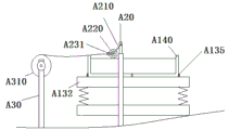
Example 2: the temporary storage tank is arranged on a manipulator A50, the manipulator comprises a base and a first motor A510 with a vertical output shaft fixed on the base, the output shaft of the first motor is fixedly connected with a second motor A520 with a longitudinal output shaft, the output shaft of the second motor is fixedly connected with a first swing arm A530, the upper end of the first swing arm is fixedly provided with a horizontal cross arm A540 which is horizontally arranged, the end part of the horizontal cross arm is hinged and connected with the temporary storage tank through a bearing, the position of the temporary storage tank A410 can be adjusted by utilizing the first motor and the second motor, a negative pressure pump A440 inputs stirred concrete into the temporary storage tank through a negative pressure pipe, a blanking pipe A430 with the temporary storage tank A410 is kept towards the lower part, and the blanking pipe A430 is controlled to be opened and closed by an electromagnetic valve.
Example 3: as shown in fig. 5 to 7, in this embodiment, the reinforcing bar binding device is disposed beside the vibrating table a10, and includes a hollow rectangular frame a60, the upper surface of the rectangular frame is uniformly fixed with a reinforcing bar fixing seat a70, the reinforcing bar fixing seat a70 includes a pair of opposite crutch-shaped supports a710, a gap between the longitudinal parts of the crutch-shaped supports a710 forms a gap that falls into the reinforcing bar a100, a bottom plate a610 is fixed at the bottom of the rectangular frame a60, and a motor a620 for driving the rectangular frame to rotate is fixed at the center of the bottom plate.
In this embodiment, the longitudinal portion of the crutch-shaped support a710 is higher than twice the diameter of the steel bar, the transverse portion of the crutch-shaped support is fixed on the upper surface of the rectangular frame by bolts, the transverse portion of the crutch-shaped support is provided with bolt holes for the bolts to pass through, and the upper surface of the rectangular frame is provided with a channel or a bolt hole for the bolts to pass through.
During operation, the reinforcement fixing seat A70 is arranged on the rectangular frame A60 according to the formed size of the reinforcement mesh and the spacing between the reinforcement bars, the reinforcement bars are placed into the reinforcement bar fixing seats A70 on the two corresponding sides longitudinally or transversely, the reinforcement bars fall between the longitudinal parts of the crutch-shaped support A710 to limit, after the reinforcement bars of the same row are placed, the frame motor A620 rotates for 90 degrees, and the reinforcement bars perpendicular to the reinforcement bars placed in advance can be continuously built in the same direction, so that the reinforcement bar layout forming the reinforcement mesh is completed, and then the staggered reinforcement bars of the transverse and longitudinal directions are bound.
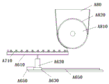
In this embodiment, in order to conveniently perform the unloading of reinforcing steel bar, in this embodiment, the lower extreme of frame motor a620 is fixed in on slide a630, the slide is driven horizontal migration by drive arrangement, the upper portion side of frame has the reinforcing steel bar hopper 80 under depositing the reinforcing steel bar, the middle part of hopper under the reinforcing steel bar has the reinforcing steel bar output roller A810 that is used for exporting the reinforcing steel bar under the reinforcing steel bar, the reinforcing steel bar output roller is rotated by motor drive, the surface interval of reinforcing steel bar output roller is provided with the recess A820 that is used for exporting the reinforcing steel bar, and reinforcing steel bar hopper both sides are pressed close to with reinforcing steel bar output roller surface and prevent that the reinforcing steel bar from deviate from by the lateral part, and the bottom of hopper under the reinforcing steel bar has feed opening A830 under the reinforcing steel bar.
In this embodiment, the driving device is a slide cylinder a140, a slide rail a650 is disposed below the slide, and a mating surface of the slide seat a630 and the slide rail a650 is i-shaped.
During operation, the steel bars are axially placed along the steel bar output roller A810 in the steel bar discharging hopper, when the steel bars meet the grooves of the steel bar output roller along with the rotation of the steel bar output roller, the steel bars can fall into the grooves, then the groove depth of the steel bar output roller can only fall into one steel bar, when the grooves are exposed from the blanking port A830 below the steel bar discharging hopper A80 along with the rotation of the steel bar output roller, the steel bars directly fall down along with the movement of the sliding seat electric cylinder A640, the rectangular frame is utilized to move along the direction parallel to the axial direction of the steel bar output roller, the steel bars falling from the blanking port A830 fall into the steel bar fixing seats A70 in the same row one by one correspondingly, after the steel bars in the same row fall into the same row, the frame motor A620 rotates for 90 degrees, the steel bar layout vertical to the steel bars which are arranged in advance can be continuously built along the same direction, then the manufacturing of the steel bar mesh can be completed, the steel bar mesh can be completed by binding the transverse and longitudinal staggered steel bar intersection, the completed steel bar mesh is placed into a die to be poured through a mechanical device, and then the pouring device is used for pouring.
During installation, the steel bar discharging hopper A80 is fixed on the ground through a supporting body, the steel bar output roller is driven to rotate through a motor fixed on the supporting body, and the rotating speed is matched with the moving speed of the sliding seat electric cylinder, so that the steel bar output roller can place steel bars in grooves of the steel bar output roller into the steel bar fixing seats A70 of the rectangular frames in the same row one by one.
Example 4: as shown in fig. 8 to 13, the cleaning device of the mixer comprises a linear guide rail B27 positioned at the side of the mixer and a guide seat B28 capable of moving along the linear guide rail, wherein a lifting table B29 is arranged above the guide seat, a high-pressure water gun B30, a water tank B35 and a water pump B36 are arranged above the lifting table, the high-pressure water gun B30 and the water tank B35 are rotatable and the spray head of the high-pressure water gun is positioned at the opening part above the mixer, and the water pump B36 is used for conveying water in the water tank into the high-pressure water gun.
The guide groove matched with the linear guide rail is arranged below the guide seat.
The high-pressure water gun comprises a high-pressure water pipe B31 which is in a bent shape or a bent shape, a high-pressure spray head B32 positioned above the stirring machine is arranged at the upper end of the high-pressure water pipe, and high-pressure spray nozzles B33 are arranged on the periphery and the bottom of the high-pressure spray head.
The bottom of the high-pressure water pipe is provided with a support shaft B34, a bearing B37 used for supporting the support shaft to penetrate is arranged in the lifting platform for enhancing the rotation stability of the high-pressure water pipe, and a motor B38 used for driving the support shaft to rotate is arranged in the lifting platform.
The high-pressure water pipe is connected with the water pump by adopting the hose B39, and the hose needs to have a certain length, so that the influence on the rotation of the high-pressure water pipe is avoided.
The guide seat is internally provided with the cylinder B40 for driving the lifting platform to move up and down, in order to strengthen the lifting stability of the lifting platform, four guide posts B41 are further arranged between the lifting platform and the guide seat, the four guide posts can be distributed at four corners of the lifting platform, the lower ends of the guide posts are fixedly connected with the guide seat, and the upper ends of the guide posts penetrate through the lifting platform.
When the cleaning device of the civil engineering laboratory mixer works, the guide seat moves along the linear guide rail to be close to the mixer B17, the motor rotates to drive the high-pressure water pipe to rotate for a certain angle, the high-pressure nozzle of the high-pressure water gun moves to the upper opening position of the mixer, the cylinder drives the lifting table to descend, the high-pressure nozzle moves from top to bottom inside the mixer, the water pump pumps cleaning liquid in the water tank to the high-pressure water pipe, the cleaning liquid is sprayed out through the plurality of nozzles of the high-pressure nozzle to clean the inside of the mixer, and in the cleaning process, the cylinder can drive the lifting table to move up and down in a certain range, so that the high-pressure nozzle can clean the inside of the mixer more comprehensively; furthermore, it should be noted here that during the cleaning process, the stirring shaft inside the stirrer can also be rotated, which is advantageous for better cleaning, and finally, after cleaning, the sewage is discharged from the discharge opening of the stirrer.
In the embodiment, a concrete distributing and stirring device is arranged above the high-pressure water gun, the concrete distributing and stirring device comprises a frame B20, a plurality of material tanks B15 are arranged at the upper part of the frame, and materials in the material tanks B15 are not only stones and sand, but also cement, additives and the like; the lower part of each material tank is provided with a weighing hopper B16, the lower part of each weighing hopper B16 is provided with a stirrer B17, the lower part of a discharge port of each stirrer B17 is provided with a discharge hopper truck B18 positioned on a discharge track B19, each material tank B15 is used for containing ingredients of civil engineering test concrete, the shape of each material tank B15 is a cylindrical body, the lower parts of each material tank B15 are respectively provided with a control valve, each control valve is connected with a material guide channel B26, the lower outlet of each material guide channel is opposite to the upper opening of the corresponding weighing hopper B16, after the control valve is opened, materials in each material tank B15 enter the weighing hopper B16 after passing through the corresponding material guide channel B26, each weighing hopper B16 is used for weighing, each weighing hopper is a conventional weighing hopper, the lower end of each weighing hopper B16 is provided with an on-off control valve for realizing discharging, each stirrer B17 is used for stirring materials, and each discharge hopper truck B18 is used for conveying and discharging materials.
Further, for reasonable in design, above-mentioned frame B20 includes that many upright posts B21 that erect the setting, establish first platform B22 and second platform B23 on pole setting B21, and frame B20 can be formed by square steel pipe welding, second platform B23 is higher than first platform B22, material jar B15 is established in the pore canal of second platform B23, be equipped with funnel B24 on the first platform B22, weighing hopper B16 is fixed on the frame B25 of first platform, and weighing hopper B16's lower discharge gate is just to the upper opening of funnel B24, all is equipped with weighing sensor between first platform B22, second platform B23 and material jar B15, weighing hopper B16 to realize weighing, weighing sensor to material jar B15, weighing hopper B16 can be C3, C6 grade respectively.
The frame 25 is a rectangular frame, and is formed by welding four vertical rods below rectangular frames connected with four cross rods, each weighing hopper B16 is arranged in the rectangular frame, a C6-level weighing sensor is arranged between each weighing hopper B16 and each rectangular frame, the hopper B24 is a conical hopper, the upper opening diameter of the conical hopper is larger than the lower size of each weighing hopper B16, so that materials in each weighing hopper B16 can fall into the hopper B24, and the lower opening of the conical hopper faces the feed inlet of the mixer B17.
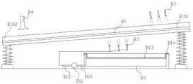
In this embodiment, a material cleaning and drying device is disposed on the front side of the material tank, where the material cleaning and drying device includes a first vibrating mesh screen B1, an upper flushing head B2 and a lower flushing head B3 disposed above and below the first vibrating mesh screen, the upper flushing head and the lower flushing head face the first vibrating mesh screen, a hot air nozzle B4 is disposed on the second side above the first vibrating mesh screen, the hot air nozzle faces the first vibrating mesh screen, a first end B101 of the first vibrating mesh screen B1 is higher than a second end, a first end of the first vibrating mesh screen is sequentially connected with a first sloping plate and a first sloping conveyor belt, and a second end B102 of the first vibrating mesh screen is sequentially connected with a second sloping plate B7 and a second sloping conveyor belt B8; the first vibrating mesh screen 1 can be a metal mesh screen, sediment and the like are removed through a vibrating motor driving vibrating screen, the upper flushing head B2 and the lower flushing head B3 can be shower heads, the shower heads are provided with mud for flushing stones and sand under the action of certain water pressure, the hot air spray heads B4 are electric air blowing, the drying of water on stones and sand is realized, and the hot air spray heads B4 can be one or a plurality of.
During operation, the materials (such as stones and sand) with treatment are input into the first end of the first vibrating mesh screen, and are conveyed from the first end to the second end along with the vibration of the first vibrating mesh screen, and the upper flushing head and the lower flushing head flush the first vibrating mesh screen in the conveying process, so that the stones and sand on the first vibrating mesh screen are flushed, and the soil attached to the stones and sand is removed, so that the accuracy of subsequent tests is ensured; and meanwhile, when the stones or sand are conveyed to the second end of the first vibration mesh screen, the stones or sand on the first vibration mesh screen is thermally blown by the hot air nozzle, so that the stones or sand can be dried, the moisture content in the stones or sand can be reduced, and the accuracy of a subsequent test can be ensured.
Further, the upper flushing head B2 and the lower flushing head B3 are respectively provided with three upper flushing heads B2 which are mutually parallel and form an included angle of 120 degrees with the horizontal plane, and the three lower flushing heads B3 are mutually parallel and form an included angle of-120 degrees with the horizontal plane.
A water containing tank is arranged below the first vibration mesh screen, is sequentially connected with a water delivery pipe B10 and a water delivery pump B11, and is communicated with an upper flushing head and a lower flushing head through pipelines; the upper part in the water containing tank B9 is provided with a filter net bag B13 which is in a groove shape, and the side part of the filter net bag is provided with a hook B14 which is hung on the side wall opening of the water containing tank B9; the muddy water flowing down from the first vibrating mesh screen 1 is filtered by the filter net bag B13, so that the water entering the water containing tank B9 is cleaner, a certain water circulation can be realized, and the water supply of the upper flushing head B2 and the lower flushing head B3 can be from tap water.
The output end of the first inclined conveyor belt is higher than the first end of the first vibrating mesh screen, and meanwhile, the first inclined plate is downwards inclined from the output end of the first inclined conveyor belt and inclines towards the first end of the first vibrating mesh screen; the input end of the second inclined conveyor B8 is lower than the second end B102 of the first vibrating screen B1, and the second inclined plate B7 is downward from the second end B102 of the first vibrating screen B1 and inclined toward the input end B801 of the second inclined conveyor B8; through the design, good material transmission can be realized.
The output end B802 of the second inclined conveyor belt B8 is led to a material tank B15 of the civil engineering laboratory concrete material distributing and stirring device on the frame B20, and the material is cleaned by the material cleaning and drying device of the civil engineering laboratory, so that the follow-up test is ensured to be more accurate, and the material is fed to the concrete material distributing and stirring device of the civil engineering laboratory for material distributing and stirring after the material is cleaned.
Any of the above-described embodiments of the present invention disclosed herein, unless otherwise stated, if they disclose a numerical range, then the disclosed numerical range is the preferred numerical range, as will be appreciated by those of skill in the art: the preferred numerical ranges are merely those of the many possible numerical values where technical effects are more pronounced or representative. Since the numerical values are more and cannot be exhausted, only a part of the numerical values are disclosed to illustrate the technical scheme of the invention, and the numerical values listed above should not limit the protection scope of the invention.
Meanwhile, if the above invention discloses or relates to parts or structural members fixedly connected with each other, the fixed connection may be understood as follows unless otherwise stated: detachably fixed connection (e.g. using bolts or screws) can also be understood as: the non-detachable fixed connection (e.g. riveting, welding), of course, the mutual fixed connection may also be replaced by an integral structure (e.g. integrally formed using a casting process) (except for obviously being unable to use an integral forming process).
In addition, terms used in any of the above-described aspects of the present disclosure to express positional relationship or shape have meanings including a state or shape similar to, similar to or approaching thereto unless otherwise stated.
Any part provided by the invention can be assembled by a plurality of independent components, or can be manufactured by an integral forming process.
Finally, it should be noted that the above-mentioned embodiments are only for illustrating the technical scheme of the present invention and are not limiting; while the invention has been described in detail with reference to the preferred embodiments, those skilled in the art will appreciate that: modifications may be made to the specific embodiments of the present invention or equivalents may be substituted for part of the technical features thereof; without departing from the spirit of the invention, it is intended to cover the scope of the invention as claimed.
Claims (8)
1. The automatic manufacturing device for the samples in the civil engineering laboratory is characterized by comprising a material cleaning and drying device, a concrete distributing and stirring device, a stirring machine cleaning device, a cement pumping pouring die device, a vibrating and laminating device and a reinforcing steel bar bundling device which are sequentially arranged, wherein the vibrating and laminating device comprises a vibrating table, the vibrating table comprises a base and a vibrating motor fixed above the base, an output shaft of the vibrating motor is fixedly provided with a rotary table, the rotary table is eccentrically connected with a supporting table, the supporting table is used for placing a die, the side part of the base is provided with a vertical support, the top of the vertical support is hinged with a swinging swing rod, the swing rod is transversely hinged with a rolling press roll, the rear side of the vertical support is also fixedly provided with a clamp capable of clamping a film, the vertical support is driven to transversely move by a support driving device, the cement pumping pouring die device comprises a pouring device positioned above the vibrating table, the pouring device comprises a temporary storage tank, the temporary storage tank is connected with a negative pressure pipe, a blanking pipe for discharging the material is arranged below the temporary storage tank, the temporary storage tank is provided with a blanking pipe for discharging the negative pressure, and the blanking pipe is provided with a solenoid valve for controlling the opening and closing of the blanking pipe;
The steel bar bundling device comprises a hollow rectangular frame, wherein a steel bar fixing seat is uniformly fixed on the upper surface of the rectangular frame, the steel bar fixing seat comprises a pair of crutch-shaped supports which are arranged in opposite directions, gaps between longitudinal parts of the crutch-shaped supports form gaps for falling into steel bars, a bottom plate is fixed at the bottom of the rectangular frame, and a motor for driving the rectangular frame to rotate is fixed at the center of the bottom plate;
the lower end of the frame motor is fixed on a slide seat, the slide seat is driven by an electric cylinder to move horizontally, a steel bar discharging hopper for storing steel bars is arranged at the side of the upper part of the frame, a steel bar output roller for outputting the steel bars is arranged at the middle part of the steel bar discharging hopper and is driven by the motor to rotate, grooves for outputting the steel bars are formed in the surface of the steel bar output roller at intervals, two sides of the steel bar discharging hopper are close to the surface of the steel bar output roller to prevent the steel bars from being separated from the side parts, a discharging opening is formed in the bottom of the steel bar discharging hopper, a sliding rail is arranged below the slide seat, and the matching surface of the slide seat and the sliding rail is I-shaped; the vertical portion of turning form support is higher than twice bar diameter, the horizontal portion of turning form support passes through the bolt fastening at rectangular frame upper surface, the horizontal portion of turning form support has the bolt hole that passes for the bolt, rectangular frame upper surface has the channel or the bolt hole that pass for the bolt, and rectangular frame's opposite side fixed bar fixing base symmetry sets up.
2. The automated manufacturing apparatus for samples in civil engineering laboratory according to claim 1, wherein a vision camera or a laser sensor is fixed to the temporary storage tank.
3. The automated manufacturing device for samples in civil engineering laboratory according to claim 2, wherein the support table comprises a lower support table eccentrically hinged to the turntable and an upper support table connected to the upper part of the lower support table through a spring, the surface of the upper support table is provided with a limit hole, and a limit rod for limiting the die is inserted into the limit hole; a film support arranged vertically is fixed on the side of the base, a film conveying roller is hinged on the film support, a film is wound on the film conveying roller, the clamp comprises a pair of clamping plates fixedly connected through bolts, one clamping plate is fixed on the swing rod, and the film is clamped between the two clamping plates; the vertical supports are provided with a pair of swing rods, the two vertical supports are connected through a connecting rod, the pressing roller is hinged to the connecting rod, the length of the pressing roller is consistent with the side length of the corresponding die side, the bottom of each vertical support is fixedly provided with a sliding block, two sides of the base are fixedly provided with guide rails matched with the sliding blocks, the guide rails are matched with the sliding blocks to form an I shape, and the support driving device is a support electric cylinder.
4. The automatic sample manufacturing device for the civil engineering laboratory of claim 1, wherein the temporary storage tank is arranged on a manipulator, the manipulator comprises a base and a first motor with a vertical output shaft fixed on the base, the output shaft of the first motor is fixedly connected with a second motor with a longitudinal output shaft, the output shaft of the second motor is fixedly connected with a first swing arm, the upper end of the first swing arm is fixedly provided with a horizontal cross arm arranged horizontally, and the end part of the horizontal cross arm is hinged with the temporary storage tank through a bearing.
5. The automatic manufacturing device for samples in civil engineering laboratories according to claim 1, wherein the material cleaning and drying device comprises a first vibrating screen, an upper flushing head and a lower flushing head which are arranged above and below the first vibrating screen, wherein the upper flushing head and the lower flushing head face the first vibrating screen, a hot air spray head is arranged on a second side above the first vibrating screen, the hot air spray head faces the first vibrating screen, a first end of the first vibrating screen is higher than a second end of the first vibrating screen, the first end of the first vibrating screen is sequentially connected with a first sloping plate and a first sloping conveyor belt, and a second end of the first vibrating screen is sequentially connected with a second sloping plate and a second sloping conveyor belt; the upper flushing heads and the lower flushing heads are respectively provided with three upper flushing heads which are parallel to each other and form an included angle of 120 degrees with the horizontal plane, and the three lower flushing heads are parallel to each other and form an included angle of-120 degrees with the horizontal plane; a water containing tank is arranged below the first vibration mesh screen, is sequentially connected with a water pipe and a water delivery pump, and is communicated with an upper flushing head and a lower flushing head through pipelines; the upper part of the water containing tank body is provided with a filtering net bag which is in a tank shape, and the side part of the filtering net bag is provided with a hook which is hung on the side wall opening of the water containing tank; the output end of the first inclined conveyor belt is higher than the first end of the first vibrating mesh screen, and meanwhile, the first inclined plate is downwards inclined from the output end of the first inclined conveyor belt and inclines towards the first end of the first vibrating mesh screen; the input end of the second inclined conveyor belt is lower than the second end of the first vibrating mesh screen, and the second inclined plate is downwards inclined from the second end of the first vibrating mesh screen and inclines towards the input end of the second inclined conveyor belt; the output end of the second inclined conveyor belt is communicated with a material tank positioned on the frame; a plurality of material tanks are arranged at the upper part of the frame, a weighing hopper is arranged below each material tank, a stirrer is arranged below each weighing hopper, and a discharging hopper car positioned on a discharging track is arranged below a discharging port of the stirrer; the machine frame comprises a plurality of upright rods, a first platform and a second platform, wherein the upright rods are vertically arranged, the first platform and the second platform are arranged on the upright rods, the second platform is higher than the first platform, the material tank is arranged in a pore canal of the second platform, a funnel is arranged on the first platform, the weighing hopper is fixed on a frame of the first platform, and a lower discharge hole of the weighing hopper is opposite to an upper opening of the funnel; the lower part of the material tank is provided with a material guide channel, and the lower outlet of the material guide channel is opposite to the upper opening of the weighing hopper.
6. The automatic manufacturing device for samples in civil engineering laboratories according to claim 5, wherein the concrete distributing and stirring device comprises a frame, a plurality of material tanks are arranged on the upper part of the frame, a weighing hopper is arranged below each material tank, a stirrer is arranged below each weighing hopper, and a discharging hopper car positioned on a discharging track is arranged below a discharging hole of the stirrer; the machine frame comprises a plurality of upright rods, a first platform and a second platform, wherein the upright rods are vertically arranged, the first platform and the second platform are arranged on the upright rods, the second platform is higher than the first platform, the material tank is arranged in a pore canal of the second platform, a funnel is arranged on the first platform, the weighing hopper is fixed on a frame of the first platform, and a lower discharge hole of the weighing hopper is opposite to an upper opening of the funnel; the lower part of the material tank is provided with a material guide channel, and the lower outlet of the material guide channel is opposite to the upper opening of the weighing hopper; the material tank is used for containing various ingredients of civil engineering test concrete, the material tank is in a cylindrical shape, the lower parts of the material tank are provided with control valves, each control valve is connected with a material guide channel, and the lower outlet of the material guide channel is opposite to the upper opening of the corresponding weighing hopper; and weighing sensors are arranged between the first platform and the second platform and the material tank and between the first platform and the weighing hopper so as to realize weighing, and the weighing sensors of the material tank and the weighing hopper are respectively of C3 and C6 grades.
7. The automatic manufacturing device for samples in civil engineering laboratories according to claim 1, wherein the cleaning device for the mixer comprises a linear guide rail positioned at the side part of the mixer and a guide seat capable of moving along the linear guide rail, a lifting table is arranged above the guide seat, a high-pressure water gun, a water tank and a water pump are arranged above the lifting table, wherein the high-pressure water gun is rotatable, a spray head is positioned at an opening above the mixer, and the water pump is used for conveying water in the water tank into the high-pressure water gun; the high-pressure water gun comprises a high-pressure water pipe which is in a bent shape or a bent shape, a high-pressure spray head which is positioned above the stirring machine is arranged at the upper end of the high-pressure water pipe, and high-pressure spray nozzles are arranged at the periphery and the bottom of the high-pressure spray head; the bottom of the high-pressure water pipe is provided with a support shaft, a bearing used for penetrating the support shaft is arranged in the lifting platform, and a motor used for driving the support shaft to rotate is arranged in the lifting platform; the high-pressure water pipe is connected with the water pump by a hose; the guide seat is internally provided with an air cylinder for driving the lifting platform to move up and down, and a guide column is arranged between the lifting platform and the guide seat.
8. A method of operating an automated manufacturing apparatus for samples in a laboratory for civil engineering according to any one of claims 1 to 6, comprising the steps of: (1) Starting a material cleaning and drying device, inputting materials (such as stones and sand) to be processed into a first end of a first vibrating mesh screen, conveying the materials from the first end to a second end along with the vibration of the first vibrating mesh screen, and flushing the first vibrating mesh screen by an upper flushing head and a lower flushing head in the conveying process so as to flush the stones and sand on the first vibrating mesh screen, so that soil attached to the stones and sand is removed, and the accuracy of a subsequent test is ensured; meanwhile, when the stones or sand are conveyed to the second end of the first vibration mesh screen, the stones or sand on the first vibration mesh screen is thermally blown by the hot air nozzle, so that the stones or sand can be dried, and the moisture content in the stones or sand can be reduced; starting the concrete distributing and stirring device: each material is sent to each material tank, the materials required by the corresponding test are led into a weighing hopper below through a valve, after weighing is met, each weighing hopper is led into a stirrer below through valve control to stir, and the materials are output from a discharge port of the stirrer after stirring; (3) The cement pumping pouring device of the civil engineering laboratory works above the vibrating table, a visual camera is fixed on the temporary storage tank, and the height of the poured concrete can be fed back by the visual camera through marking the mould, so that the output concrete quantity is controlled by a battery valve or a negative pressure pump; (4) Introducing the stirred concrete into a mould, uniformly filling the materials under the drive of a vibrating motor, clamping the film conveying roller between two clamping plates by using a clamp, and locking the two clamping plates by using bolts; (5) The support electric cylinder drives the two vertical supports to synchronously move, then the vertical supports are in a moving process, in an initial state, the lower edge of the press roller is lower than the surface of the concrete to be smoothed, then the support electric cylinder drives the vertical supports to move, so that the swing rod and the press roller are driven to move together with the clamp, after the press roller contacts the die, the die is fixed on the upper supporting table, then is subjected to the propping action of the die and swings upwards, then bypasses the upper edge of the die, and then continuously moves transversely under the action of the support electric cylinder, and the press roller is pressed on the surface of the concrete in the die under the action of gravity to roll to form a plane; (6) Because the clamp is fixed on the rear side of the swing rod and positioned on the press roller, in the moving process of the vertical bracket, the swing rod drags the clamp to drag the film to cover the surface of the rolled concrete in the die after the press roller is pressed, and then the film is sheared; (7) Under the condition that a reinforcing steel bar net needs to be placed in, before a concrete is led into a die, reinforcing steel bars are placed in a reinforcing steel bar discharging hopper along the axial direction of a reinforcing steel bar discharging roller by utilizing a reinforcing steel bar binding device, when the reinforcing steel bars meet the grooves of the reinforcing steel bar discharging roller along the rotation of the reinforcing steel bar discharging roller, the reinforcing steel bars can fall into the grooves, the depth of the grooves of the reinforcing steel bar discharging roller can only fall into one reinforcing steel bar, when the grooves are exposed from the discharging opening below the reinforcing steel bar discharging hopper along the rotation of the reinforcing steel bar discharging roller, the rectangular frame moves along the direction parallel to the axial direction of the reinforcing steel bar discharging roller along the movement of a sliding seat electric cylinder, the reinforcing steel bars which fall from the discharging opening fall into the reinforcing steel bar fixing seats in the same row one by one correspondingly, after the same row of reinforcing steel bars fall into the same row, the rotation of the frame motor can be continuously built up above the reinforcing steel bars which are arranged in the same direction so as to complete the reinforcing steel bar layout which forms the reinforcing steel bar net, then the manufacturing of the reinforcing steel bar net can be completed by transversely and longitudinally staggered reinforcing steel bar staggered.
Applications Claiming Priority (2)
| Application Number | Priority Date | Filing Date | Title |
|---|---|---|---|
| CN202110450628 | 2021-04-26 | ||
| CN2021104506281 | 2021-04-26 |
Publications (2)
| Publication Number | Publication Date |
|---|---|
| CN114986706A CN114986706A (en) | 2022-09-02 |
| CN114986706B true CN114986706B (en) | 2023-05-26 |
Family
ID=83025046
Family Applications (1)
| Application Number | Title | Priority Date | Filing Date |
|---|---|---|---|
| CN202210413861.7A Active CN114986706B (en) | 2021-04-26 | 2022-04-20 | Automatic manufacturing device and method for civil engineering laboratory samples |
Country Status (1)
| Country | Link |
|---|---|
| CN (1) | CN114986706B (en) |
Families Citing this family (1)
| Publication number | Priority date | Publication date | Assignee | Title |
|---|---|---|---|---|
| CN117381938B (en) * | 2023-10-30 | 2024-03-12 | 山东冠县美安复合材料有限公司 | Cement prefabricated component pouring device |
Citations (10)
| Publication number | Priority date | Publication date | Assignee | Title |
|---|---|---|---|---|
| JP2013035052A (en) * | 2011-08-10 | 2013-02-21 | Teibyou:Kk | Method and apparatus for producing reinforcing steel mesh |
| CN110560952A (en) * | 2019-09-23 | 2019-12-13 | 北京市燕通建筑构件有限公司 | automatic reinforcing mesh welding system |
| CN210946421U (en) * | 2019-09-10 | 2020-07-07 | 陕西华中机械有限公司 | Pavement reinforcing mesh laying mechanism |
| CN211333888U (en) * | 2019-12-10 | 2020-08-25 | 天津城建大学 | Precast concrete component reinforcing bar binding machine |
| CN111774508A (en) * | 2020-07-17 | 2020-10-16 | 湖北广盛建筑产业化科技有限公司 | Assembled shear force wall reinforcing bar reinforcing equipment |
| CN111942913A (en) * | 2020-08-07 | 2020-11-17 | 中建二局第二建筑工程有限公司 | Construction steel bar conveying and measuring device |
| CN112160602A (en) * | 2020-09-03 | 2021-01-01 | 中建三局集团有限公司 | Integrated flat plate vibrator for concrete vibrating, surface collecting and film covering maintenance |
| CN112301845A (en) * | 2020-11-13 | 2021-02-02 | 唐山市星斗路桥机械有限公司 | Ultrahigh-performance concrete paving integrated machine |
| CN112392278A (en) * | 2020-11-18 | 2021-02-23 | 中国建筑第七工程局有限公司 | Simple automatic film laminating device on vibrating beam |
| CN212857560U (en) * | 2020-07-17 | 2021-04-02 | 湖北广盛建筑产业化科技有限公司 | Reinforcing bar net production facility of assembled PC component |
-
2022
- 2022-04-20 CN CN202210413861.7A patent/CN114986706B/en active Active
Patent Citations (10)
| Publication number | Priority date | Publication date | Assignee | Title |
|---|---|---|---|---|
| JP2013035052A (en) * | 2011-08-10 | 2013-02-21 | Teibyou:Kk | Method and apparatus for producing reinforcing steel mesh |
| CN210946421U (en) * | 2019-09-10 | 2020-07-07 | 陕西华中机械有限公司 | Pavement reinforcing mesh laying mechanism |
| CN110560952A (en) * | 2019-09-23 | 2019-12-13 | 北京市燕通建筑构件有限公司 | automatic reinforcing mesh welding system |
| CN211333888U (en) * | 2019-12-10 | 2020-08-25 | 天津城建大学 | Precast concrete component reinforcing bar binding machine |
| CN111774508A (en) * | 2020-07-17 | 2020-10-16 | 湖北广盛建筑产业化科技有限公司 | Assembled shear force wall reinforcing bar reinforcing equipment |
| CN212857560U (en) * | 2020-07-17 | 2021-04-02 | 湖北广盛建筑产业化科技有限公司 | Reinforcing bar net production facility of assembled PC component |
| CN111942913A (en) * | 2020-08-07 | 2020-11-17 | 中建二局第二建筑工程有限公司 | Construction steel bar conveying and measuring device |
| CN112160602A (en) * | 2020-09-03 | 2021-01-01 | 中建三局集团有限公司 | Integrated flat plate vibrator for concrete vibrating, surface collecting and film covering maintenance |
| CN112301845A (en) * | 2020-11-13 | 2021-02-02 | 唐山市星斗路桥机械有限公司 | Ultrahigh-performance concrete paving integrated machine |
| CN112392278A (en) * | 2020-11-18 | 2021-02-23 | 中国建筑第七工程局有限公司 | Simple automatic film laminating device on vibrating beam |
Also Published As
| Publication number | Publication date |
|---|---|
| CN114986706A (en) | 2022-09-02 |
Similar Documents
| Publication | Publication Date | Title |
|---|---|---|
| CN110173119B (en) | Pumping and vibrating integrated equipment for concrete construction | |
| CN209491971U (en) | A kind of uniform proportioner of concrete | |
| CN114986706B (en) | Automatic manufacturing device and method for civil engineering laboratory samples | |
| CN207177230U (en) | A kind of novel architecture Mortar spraying machine | |
| CN211221340U (en) | Concrete mixing, molding and cleaning integrated device | |
| CN211640430U (en) | Concrete production proportioning machine convenient to wash | |
| CN115032040A (en) | Civil engineering laboratory sample production testing device and method thereof | |
| CN211333945U (en) | Concrete mixing device | |
| CN2853360Y (en) | Multifunction concret mixing, transporting truck | |
| CN111923242B (en) | Recycled concrete manufacturing equipment | |
| CN206306256U (en) | A kind of shock-absorbing type concrete mixed stirring device | |
| CN107218063A (en) | Subway tunnel concrete spraying equipment and process | |
| CN205288147U (en) | Plugging construction is with joining in marriage thick liquid device | |
| CN205630988U (en) | Raw material mixing device for brickmaking | |
| CN205713125U (en) | Compact simplified concrete filling device | |
| CN209469015U (en) | A kind of architectural engineering is with pouring device | |
| CN112267469A (en) | Cement pouring equipment for building engineering | |
| CN209649109U (en) | A kind of concrete processing base-material mixing plant | |
| CN207448796U (en) | A kind of mixer in construction site | |
| CN209408864U (en) | A kind of aerated blocks casting device | |
| CN209350466U (en) | A kind of non-burning brick manufacturing equipment | |
| CN110744708A (en) | Be used for fashioned mix self-cleaning device of mix cement concrete and test piece | |
| CN218429124U (en) | Civil engineering cement watering device | |
| CN221456328U (en) | Concrete mixing equipment for building construction | |
| CN217621363U (en) | Road and bridge engineering cement dispensing equipment |
Legal Events
| Date | Code | Title | Description |
|---|---|---|---|
| PB01 | Publication | ||
| PB01 | Publication | ||
| SE01 | Entry into force of request for substantive examination | ||
| SE01 | Entry into force of request for substantive examination | ||
| GR01 | Patent grant | ||
| GR01 | Patent grant |