CN114976772B - Intelligent power distribution device based on communication cabinet - Google Patents
Intelligent power distribution device based on communication cabinet Download PDFInfo
- Publication number
- CN114976772B CN114976772B CN202210549856.9A CN202210549856A CN114976772B CN 114976772 B CN114976772 B CN 114976772B CN 202210549856 A CN202210549856 A CN 202210549856A CN 114976772 B CN114976772 B CN 114976772B
- Authority
- CN
- China
- Prior art keywords
- power distribution
- rod
- plate
- communication cabinet
- distribution box
- Prior art date
- Legal status (The legal status is an assumption and is not a legal conclusion. Google has not performed a legal analysis and makes no representation as to the accuracy of the status listed.)
- Active
Links
Images


Classifications
-
- H—ELECTRICITY
- H01—ELECTRIC ELEMENTS
- H01R—ELECTRICALLY-CONDUCTIVE CONNECTIONS; STRUCTURAL ASSOCIATIONS OF A PLURALITY OF MUTUALLY-INSULATED ELECTRICAL CONNECTING ELEMENTS; COUPLING DEVICES; CURRENT COLLECTORS
- H01R13/00—Details of coupling devices of the kinds covered by groups H01R12/70 or H01R24/00 - H01R33/00
- H01R13/62—Means for facilitating engagement or disengagement of coupling parts or for holding them in engagement
- H01R13/639—Additional means for holding or locking coupling parts together, after engagement, e.g. separate keylock, retainer strap
-
- H—ELECTRICITY
- H02—GENERATION; CONVERSION OR DISTRIBUTION OF ELECTRIC POWER
- H02B—BOARDS, SUBSTATIONS OR SWITCHING ARRANGEMENTS FOR THE SUPPLY OR DISTRIBUTION OF ELECTRIC POWER
- H02B1/00—Frameworks, boards, panels, desks, casings; Details of substations or switching arrangements
- H02B1/26—Casings; Parts thereof or accessories therefor
- H02B1/46—Boxes; Parts thereof or accessories therefor
- H02B1/48—Mounting of devices therein
-
- Y—GENERAL TAGGING OF NEW TECHNOLOGICAL DEVELOPMENTS; GENERAL TAGGING OF CROSS-SECTIONAL TECHNOLOGIES SPANNING OVER SEVERAL SECTIONS OF THE IPC; TECHNICAL SUBJECTS COVERED BY FORMER USPC CROSS-REFERENCE ART COLLECTIONS [XRACs] AND DIGESTS
- Y04—INFORMATION OR COMMUNICATION TECHNOLOGIES HAVING AN IMPACT ON OTHER TECHNOLOGY AREAS
- Y04S—SYSTEMS INTEGRATING TECHNOLOGIES RELATED TO POWER NETWORK OPERATION, COMMUNICATION OR INFORMATION TECHNOLOGIES FOR IMPROVING THE ELECTRICAL POWER GENERATION, TRANSMISSION, DISTRIBUTION, MANAGEMENT OR USAGE, i.e. SMART GRIDS
- Y04S10/00—Systems supporting electrical power generation, transmission or distribution
- Y04S10/40—Display of information, e.g. of data or controls
Landscapes
- Engineering & Computer Science (AREA)
- Power Engineering (AREA)
- Distribution Board (AREA)
Abstract
The invention discloses an intelligent power distribution device based on a communication cabinet, which comprises the communication cabinet, wherein a power distribution box body is arranged in the communication cabinet, an interface end is arranged in the middle of the front end of the power distribution box body, a slot is arranged in the middle of a bearing plate, a fixing component is arranged in the middle of one side of the bearing plate, a clamping device is correspondingly arranged at the front end of the power distribution box body and at one end of the interface end, the clamping device comprises a limiting plate corresponding to one end of the interface end, clamping plates corresponding to the slot are arranged on two sides of the limiting plate, a positioning hole is arranged in the middle of each clamping plate, a plurality of limiting grooves are arranged at the upper end of the middle of each limiting plate, a line card component corresponding to each limiting groove is arranged in each limiting plate, and an elastic component is arranged between each limiting plate and each clamping plate. Has the advantages that: the problem that the connection part of the wire end and the power distribution box is separated easily by external pulling force to influence the normal use of the power distribution box is effectively avoided.
Description
Technical Field
The invention relates to the technical field of power distribution, in particular to an intelligent power distribution device based on a communication cabinet.
Background
With the increasing importance degree of the electric power communication bearing service, the power supply of the communication equipment occupies an important position in the communication module of the electric power system, and under the premise of rapid development of scientific technology and continuous perfection of communication theory, the electric power communication power supply in China is further improved and developed towards the aspects of equipment integration, networking monitoring, maintenance-free and the like.
At present, the erection position is limited due to the quantity and the position of the power distribution devices in the cabinet, and power lines and other distribution wires cannot be properly arranged, so that the power distribution box does not have a good wire fixing mechanism for the connection position of the distribution wires, and the connection position of the wire end and the power distribution box is easy to be pulled by external force to separate the wire end and the power distribution box, therefore, the jack position of the power distribution device does not have protective measures, and safety accidents are easy to cause.
An effective solution to the problems in the related art has not been proposed yet.
Disclosure of Invention
The invention provides an intelligent power distribution device based on a communication cabinet, aiming at the problems in the related art, so as to overcome the technical problems in the prior related art.
Therefore, the invention adopts the following specific technical scheme:
the utility model provides an intelligent power distribution device based on communication rack, includes the communication rack, the inside of communication rack is provided with the power distribution box, the front end middle part of power distribution box is provided with the interface end, be provided with a plurality of connecting jack on the interface end, upper end one side of interface end is provided with the display screen, the front end of power distribution box just is located the both sides of interface end all are provided with accepts the board, the middle part of accepting the board is provided with the slot, it is provided with fixed subassembly to accept one side middle part of board, the front end of power distribution box just is located the one end correspondence of interface end is provided with the screens device, the screens device is including being located the limiting plate that interface end one end corresponds, the both sides of limiting plate all are provided with the cardboard that the slot corresponds, the middle part of cardboard is provided with the locating hole, the middle part upper end of limiting plate is provided with a plurality of spacing grooves, the inside of limiting plate be provided with the corresponding ply-yarn drill subassembly in spacing groove, the limiting plate with be provided with elastic component between the cardboard, be provided with the circuit board that the power distribution box connects, the circuit board pass through relay, alternating current contactor two and the interface end is connected, be provided with the distribution control circuit board.
Furthermore, the front end both sides of power distribution box all are provided with the mounting panel, the middle part both sides of mounting panel all are provided with the mounting hole, the mounting panel with fixed connection between the power distribution box.
Furthermore, the front end of the power distribution box body is positioned above the interface end, and state warning lamps are arranged at the front end of the power distribution box body, and the number of the state warning lamps is six.
Furthermore, the fixed subassembly is including being located accept the connecting cylinder of board one side, the middle part interlude of connecting cylinder is provided with and runs through accept board one side and extend to the inside locating lever of slot, the locating lever with the corresponding joint of locating hole.
Furthermore, the other end of the middle of the connecting cylinder is provided with a pulling rod penetrating through the connecting cylinder, a movable plate is arranged between the pulling rod and the locating rod, the movable plate is fixedly connected with the pulling rod and the locating rod, the pulling rod is located inside the connecting cylinder and located on one side of the movable plate, a first spring is sleeved on the first spring, and one end of the pulling rod is provided with a pull ring.
Further, upper end one side middle part of connecting cylinder is provided with a vertical section of thick bamboo, the middle part of a vertical section of thick bamboo is provided with the interlude the montant of connecting cylinder, the montant is located the inside lower extreme of a vertical section of thick bamboo is provided with the lifter plate, the montant is located the last pot head of lifter plate is equipped with spring two, the top of montant is provided with the pull rod.
Further, the ply-yarn drill subassembly is including being located the inside movable chamber of limiting plate, the lower extreme of limiting plate is provided with the interlude the dwang at the inside middle part in movable chamber, the top of dwang is provided with the interlock screw rod, the middle part in movable chamber just is located the top of interlock screw rod is provided with the dead lever, the both ends of dead lever all are provided with back shaft spare.
Furthermore, an internal thread block is sleeved in the middle of the linkage screw rod, two ends of the fixed rod are respectively provided with a swinging rod which is matched and connected with the support shaft piece, one end of each swinging rod is provided with linkage plates which are arranged in a staggered mode, linkage blocks are arranged between the linkage plates and correspond to each other, and two ends of the internal thread block are matched and connected with the linkage blocks through movable shafts.
Furthermore, a telescopic rod is arranged between the corresponding middle parts of the oscillating rods, the two ends of the telescopic rod are connected with the oscillating rods in a matched mode through a connecting shaft piece, a pressing block is arranged between the front ends of the oscillating rods, an arc-shaped clamping block is arranged between the front ends of the pressing block in a corresponding mode, the corresponding front ends of the arc-shaped clamping blocks are provided with anti-skidding wear-resisting pads, and the arc-shaped clamping blocks are connected with connecting wires on the rear sides of the ends of the connecting wires.
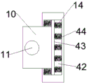
Furthermore, the elastic component comprises movable grooves located in two sides of the limiting plate, the clamping plate penetrates through an open groove in the middle of one end of each movable groove, a movable plate is arranged in the middle of each movable groove, and a plurality of springs are arranged at two ends of each movable plate.
The invention has the beneficial effects that: the firm butt of end department through spacing groove and connecting wire is in the same place, and the arc fixture block carries out the chucking to the connecting wire at middle part to reached the effect of ply-yarn drill, improved the connection steadiness between the two, effectually avoided external pulling force to make wire end and power distribution box junction break away from the problem that influences power distribution box normal use easily, simultaneously, also help the joint to connecting wire, avoid appearing connecting wire crossed phenomenon.
Drawings
In order to more clearly illustrate the embodiments of the present invention or the technical solutions in the prior art, the drawings needed in the embodiments will be briefly described below, and it is obvious that the drawings in the following description are only some embodiments of the present invention, and it is obvious for those skilled in the art to obtain other drawings without creative efforts.
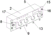
Fig. 1 is a schematic structural diagram of an intelligent power distribution apparatus based on a communication cabinet according to an embodiment of the present invention;
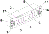
fig. 2 is a schematic view of a communication cabinet of an intelligent power distribution apparatus based on the communication cabinet according to an embodiment of the present invention;
fig. 3 is a schematic diagram of a power distribution cabinet of an intelligent power distribution apparatus based on a communication cabinet according to an embodiment of the present invention;
fig. 4 is a schematic diagram of a limiting plate of an intelligent power distribution device based on a communication cabinet according to an embodiment of the present invention;
fig. 5 is a schematic view of a socket plate of an intelligent power distribution device based on a communication cabinet according to an embodiment of the invention;
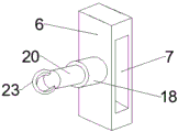
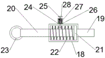
fig. 6 is a schematic diagram of a fixing component of an intelligent power distribution apparatus based on a communication cabinet according to an embodiment of the present invention;
fig. 7 is a schematic diagram of a line card assembly of an intelligent power distribution apparatus based on a communication cabinet according to an embodiment of the present invention;
fig. 8 is a schematic diagram of an internal thread block of an intelligent power distribution apparatus based on a communication cabinet according to an embodiment of the present invention;
fig. 9 is a schematic diagram of a flexible component of an intelligent power distribution apparatus based on a communication cabinet according to an embodiment of the present invention;
fig. 10 is a circuit diagram of a circuit board of an intelligent communications rack-based power distribution apparatus according to an embodiment of the present invention.
In the figure:
1. a communication cabinet; 2. a power distribution box; 3. an interface end; 4. connecting the jacks; 5. a display screen; 6. a bearing plate; 7. a slot; 8. a fixing assembly; 9. a limiting plate; 10. clamping a plate; 11. positioning holes; 12. a limiting groove; 13. a line card assembly; 14. an elastic component; 15. mounting a plate; 16. mounting holes; 17. a status warning light; 18. a connecting cylinder; 19. positioning a rod; 20. pulling a rod; 21. a movable plate; 22. a first spring; 23. a pull ring; 24. a vertical cylinder; 25. a vertical rod; 26. a lifting plate; 27. a second spring; 28. a pull rod; 29. rotating the rod; 30. linking a screw rod; 31. fixing the rod; 32. supporting the shaft member; 33. an internal thread block; 34. a swing lever; 35. a linkage plate; 36. a linkage block; 37. a telescopic rod; 38. a connecting shaft member; 39. briquetting; 40. an arc-shaped fixture block; 41. an anti-skid wear pad; 42. a movable groove; 43. moving the plate; 44. and a third spring.
Detailed Description
For further explanation of the various embodiments, the drawings which form a part of the disclosure and which are incorporated in and constitute a part of this specification, illustrate embodiments and, together with the description, serve to explain the principles of operation of the embodiments, and to enable others of ordinary skill in the art to understand the various embodiments and advantages of the invention, and, by reference to these figures, reference is made to the accompanying drawings, which are not to scale and wherein like reference numerals generally refer to like elements.
According to an embodiment of the invention, an intelligent power distribution device based on a communication cabinet is provided.
The first embodiment is as follows:
as shown in fig. 1 to 10, the intelligent power distribution device based on a communication cabinet according to an embodiment of the present invention includes a communication cabinet 1, a power distribution box 2 is disposed inside the communication cabinet 1, an interface end 3 is disposed in the middle of the front end of the power distribution box 2, a plurality of connection jacks 4 are disposed on the interface end 3, a display screen 5 is disposed on one side of the upper end of the interface end 3, receiving plates 6 are disposed on the two sides of the interface end 3 and on the front end of the power distribution box 2, slots 7 are disposed in the middle of the receiving plates 6, a fixing assembly 8 is disposed in the middle of one side of the receiving plates 6, a plurality of limiting grooves 12 are disposed at the upper end of the middle of the limiting plates 9, a wire clip assembly 13 corresponding to the limiting grooves 12 is disposed inside the limiting plates 9, a wire clip assembly 13 corresponding to the limiting grooves 12 is disposed on the two sides of the limiting plates 9, a wire clip 10 corresponding to the slots 7 is disposed in the middle of the clamping plates 10, a positioning hole 11 is disposed in the middle of the clamping plate 10, a relay distribution box 3 is connected to an ac circuit board distribution contactor, and an ac circuit board distribution contactor 14 is disposed in the communication cabinet 1.
By means of the technical scheme, the end of the connecting wire is inserted into the connecting jack 4, then the limiting groove 12 on the limiting plate 9 is close to the front end of the power distribution box body 2 along the lower end of the connecting wire, the limiting plate 10 and the bearing plate 6 are connected in a clamping mode through the fixing component 8, the limiting groove 12 of the limiting plate 9 is sleeved outside the connecting wire on the rear side of the end of the connecting wire, the end of the connecting wire is further properly extruded and limited through the springs 44 in the elastic components 14 on two sides, the end of the connecting wire can be stably abutted against the limiting groove 12, the rotating rod 29 is rotated, the linkage screw 30 on the linkage upper end is used for adjusting the inner thread block 33, the linkage blocks 36 on two ends are adjusted under the movable shaft, the linkage plates 35 on two ends drive the swinging rods 34 to swing for adjusting distance, meanwhile, the telescopic rod 37 in the middle is contracted, and the arc-shaped clamping block 40 is used for clamping the connecting wire in the middle, so that the effect of a wire clamp is achieved, the connection stability between the wire and the problem that the end of the power distribution box body is easily influenced by external pulling force is solved;
through pulling montant 25, make lifter plate 26 compress the second 27 of spring, shrink whole montant 25 from connecting cylinder 18, pull lower extreme pulling rod 20 again and remove to one side fly leaf 21 and locating lever 19, the pulling is to the one side that is located montant 25, loosen pull rod 28 and descend montant 25, make spacing fly leaf 21, and then make locating lever 19 take out from the locating hole 11 of cardboard 10, thereby unpack receiving board 6 and cardboard 10 apart, the quick assembly disassembly of limiting plate 9 and power distribution box 2 between can realizing, and convenient to use.
Example two:
as shown in fig. 1-10, mounting plates 15 are disposed on both sides of the front end of the power distribution box 2, mounting holes 16 are disposed on both sides of the middle portion of the mounting plate 15, and the mounting plate 15 is fixedly connected to the power distribution box 2. The front end of the power distribution box body 2 is positioned above the interface end 3, and the number of the state warning lamps 17 is six. Fixed subassembly 8 is including being located accept the connecting cylinder 18 of board 6 one side, the middle part interlude of connecting cylinder 18 is provided with and runs through accept board 6 one side and extend to the inside locating lever 19 of slot 7, locating lever 19 with the corresponding joint of locating hole 11. The other end of the middle of the connecting cylinder 18 is provided with a pulling rod 20 which penetrates through the connecting cylinder, a movable plate 21 is arranged between the pulling rod 20 and the positioning rod 19, the movable plate 21 and the pulling rod 20 and the positioning rod 19 are fixedly connected, the pulling rod 20 is located in the connecting cylinder 18, a first spring 22 is sleeved on one side of the movable plate 21, and a pulling ring 23 is arranged at one end of the pulling rod 20. The utility model discloses a go up the connecting cylinder 18, including connecting cylinder 18, riser 24, the middle part of riser is provided with the interlude the montant 25 of connecting cylinder 18, montant 25 is located the inside lower extreme of riser 24 is provided with lifter plate 26, montant 25 is located the last pot head of lifter plate 26 is equipped with two 27 of springs, the top of montant 25 is provided with pull rod 28.
As shown in fig. 1-10, the line card assembly 13 includes a movable cavity located inside the limiting plate 9, the lower end of the limiting plate 9 is provided with a rotating rod 29 penetrating through the inner middle part of the movable cavity, the top end of the rotating rod 29 is provided with an interlocking screw rod 30, the middle part of the movable cavity is located at the top end of the interlocking screw rod 30 and is provided with a fixing rod 31, and both ends of the fixing rod 31 are provided with supporting shaft members 32. The middle of the linkage screw rod 30 is sleeved with an inner thread block 33, two ends of the fixed rod 31 are respectively provided with a swinging rod 34 which is matched and connected with the supporting shaft 32, one end of the swinging rod 34 is provided with linkage plates 35 which are arranged in a staggered manner, linkage blocks 36 are arranged between the linkage plates 35 correspondingly, and two ends of the inner thread block 33 are matched and connected with the linkage blocks 36 through movable shafts. The middle of the swing rod 34 is correspondingly provided with a telescopic rod 37, two ends of the telescopic rod 37 are connected with the swing rod 34 through a connecting shaft 38 in a matching manner, a pressing block 39 is arranged between the front ends of the swing rod 34, arc-shaped clamping blocks 40 are arranged between the front ends of the pressing blocks 39 correspondingly, anti-skid wear-resistant pads 41 are arranged at the corresponding front ends of the arc-shaped clamping blocks 40, and the arc-shaped clamping blocks 40 are connected with connecting wires on the rear sides of the ends of the connecting wires. The elastic component 14 comprises movable grooves 42 located in two sides of the limiting plate 9, the clamping plate 10 penetrates through an open groove in the middle of one end of each movable groove 42, a moving plate 43 is arranged in the middle of each movable groove 42 of the clamping plate 10, and a plurality of springs 44 are arranged at two ends of each moving plate 43.
For the convenience of understanding the technical solutions of the present invention, the following detailed description will be made on the working principle or the operation mode of the present invention in the practical process.
In practical application, the end of the connecting wire is inserted into the connecting jack 4, the limiting groove 12 on the limiting plate 9 is connected with the receiving plate 6 through the fixing component 8 along the lower end of the connecting wire to be close to the front end of the power distribution box body 2, the limiting plate 10 is connected with the receiving plate 6 in a clamping mode, the limiting groove 12 of the limiting plate 9 is sleeved outside the connecting wire on the rear side of the end of the connecting wire, the end of the connecting wire is further properly extruded and limited through the spring three 44 in the elastic components 14 on two sides, the end of the connecting wire can be firmly abutted with the limiting groove 12, the rotating rod 29 is rotated, the linkage screw 30 on the linkage upper end is used for adjusting the inner thread block 33, the linkage blocks 36 on two ends are adjusted under the movable shaft, the linkage plates 35 on two ends drive the swinging rod 34 to swing for adjusting distance, meanwhile, the telescopic rod 37 in the middle is contracted, and the arc-shaped fixture block 40 is used for clamping the connecting wire in the middle, so that the effect of a wire clamp is achieved, the connection stability between the two ends is improved, and the problem that the end of the power distribution box body is easily influenced by external pulling force is easily distributed;
through pulling montant 25, make lifter plate 26 compress the second 27 of spring, shrink whole montant 25 from connecting cylinder 18, pull lower extreme pulling rod 20 again and remove to one side fly leaf 21 and locating lever 19, the pulling is to the one side that is located montant 25, loosen pull rod 28 and descend montant 25, make spacing fly leaf 21, and then make locating lever 19 take out from the locating hole 11 of cardboard 10, thereby unpack receiving board 6 and cardboard 10 apart, the quick assembly disassembly of limiting plate 9 and power distribution box 2 between can realizing, and convenient to use.
In summary, according to the above technical solution of the present invention, the limiting groove 12 is firmly abutted against the end of the connecting wire, and the arc-shaped fixture block 40 clamps the connecting wire at the middle part, so as to achieve the effect of the wire clamp, improve the connection stability between the limiting groove and the connecting wire, effectively avoid the problem that the connection between the end of the wire and the power distribution box is easily separated by external pulling force, which affects the normal use of the power distribution box, and at the same time, facilitate the clamping of the connecting wire, and avoid the crossing phenomenon of the connecting wire.
The above description is only for the purpose of illustrating the preferred embodiments of the present invention and is not to be construed as limiting the invention, and any modifications, equivalents, improvements and the like that fall within the spirit and principle of the present invention are intended to be included therein.
Claims (7)
1. The intelligent power distribution device based on the communication cabinet is characterized by comprising the communication cabinet (1), a power distribution box body (2) is arranged in the communication cabinet (1), an interface end (3) is arranged in the middle of the front end of the power distribution box body (2), a plurality of connecting jacks (4) are arranged on the interface end (3), a display screen (5) is arranged on one side of the upper end of the interface end (3), bearing plates (6) are arranged at the front end of the power distribution box body (2) and positioned on two sides of the interface end (3), slots (7) are arranged in the middle of the bearing plates (6), a fixing component (8) is arranged in the middle of one side of each bearing plate (6), a clamping device is correspondingly arranged at one end of the front end of the power distribution box body (2) and positioned on the interface end (3), a limiting plate (9) corresponding to one end of the interface end (3) is arranged on each side of each limiting plate (9), clamping plates (10) corresponding to the slots (7) are arranged on two sides of each clamping plate (9), a plurality of positioning holes (11) are arranged in the middle of the clamping plates (9), and a plurality of limiting grooves (12) are arranged in the limiting grooves (12), an elastic component (14) is arranged between the limiting plate (9) and the clamping plate (10), a circuit board connected with the power distribution box body (2) is arranged in the communication cabinet (1), the circuit board is connected with the interface end (3) through a relay, an alternating current contactor I and an alternating current contactor II, and a distribution control circuit is arranged on the circuit board; the fixing assembly (8) comprises a connecting cylinder (18) positioned on one side of the bearing plate (6), a positioning rod (19) penetrating through one side of the bearing plate (6) and extending into the slot (7) is inserted into the middle of the connecting cylinder (18), and the positioning rod (19) is correspondingly clamped with the positioning hole (11); a pulling rod (20) penetrating through the connecting cylinder (18) is arranged at the other end of the middle of the connecting cylinder (18), a movable plate (21) is arranged between the pulling rod (20) and the positioning rod (19), a fixed connecting structure is arranged between the movable plate (21) and the pulling rod (20) and the positioning rod (19), a first spring (22) is sleeved on one side, located in the connecting cylinder (18), of the pulling rod (20) and located on the movable plate (21), and a pull ring (23) is arranged at one end of the pulling rod (20); the upper end one side middle part of connecting cylinder (18) is provided with vertical section of thick bamboo (24), the middle part of vertical section of thick bamboo (24) is provided with the interlude montant (25) of connecting cylinder (18), montant (25) are located the inside lower extreme of vertical section of thick bamboo (24) is provided with lifter plate (26), montant (25) are located the upper end cover of lifter plate (26) is equipped with spring two (27), the top of montant (25) is provided with pull rod (28).
2. The intelligent power distribution device based on the communication cabinet as claimed in claim 1, wherein mounting plates (15) are arranged on both sides of the front end of the power distribution cabinet (2), mounting holes (16) are arranged on both sides of the middle of the mounting plates (15), and the mounting plates (15) are fixedly connected with the power distribution cabinet (2).
3. The intelligent power distribution device based on the communication cabinet as claimed in claim 1, wherein status warning lights (17) are disposed at the front end of the power distribution cabinet (2) and above the interface end (3), and the number of the status warning lights (17) is six.
4. The intelligent power distribution device based on the communication cabinet as claimed in claim 1, wherein the line card assembly (13) includes a movable cavity located inside the limiting plate (9), a rotating rod (29) inserted into the middle inside the movable cavity is disposed at the lower end of the limiting plate (9), an interlocking screw rod (30) is disposed at the top end of the rotating rod (29), a fixing rod (31) is disposed at the middle of the movable cavity and at the top end of the interlocking screw rod (30), and support shaft members (32) are disposed at both ends of the fixing rod (31).
5. The intelligent power distribution device based on the communication cabinet as claimed in claim 4, wherein an internal thread block (33) is sleeved at the middle of the linkage screw (30), swing rods (34) which are in fit connection with the support shaft member (32) are respectively arranged at both ends of the fixed rod (31), linkage plates (35) are arranged at one ends of the swing rods (34) in a staggered manner, linkage blocks (36) are respectively arranged between the linkage plates (35) in correspondence, and both ends of the internal thread block (33) are in fit connection with the linkage blocks (36) through movable shafts.
6. The intelligent power distribution device based on the communication cabinet as claimed in claim 5, wherein an expansion link (37) is correspondingly arranged in the middle of the swing rod (34), two ends of the expansion link (37) are connected with the swing rod (34) through a connecting shaft member (38), a pressing block (39) is arranged between the front ends of the swing rod (34), an arc-shaped clamping block (40) is correspondingly arranged between the front ends of the pressing block (39), the corresponding front ends of the arc-shaped clamping blocks (40) are respectively provided with an anti-skid wear-resistant pad (41), and the arc-shaped clamping block (40) is connected with a connecting wire at the rear side of the end of the connecting wire.
7. The intelligent power distribution device based on the communication cabinet as claimed in claim 1, wherein the elastic assembly (14) comprises movable grooves (42) located inside two sides of the limiting plate (9), the clamping plate (10) is inserted into an open groove in the middle of one end of the movable groove (42), a moving plate (43) is disposed in the middle of the movable groove (42) of the clamping plate (10), and a plurality of springs (44) are disposed at two ends of the moving plate (43).
Priority Applications (1)
| Application Number | Priority Date | Filing Date | Title |
|---|---|---|---|
| CN202210549856.9A CN114976772B (en) | 2022-05-20 | 2022-05-20 | Intelligent power distribution device based on communication cabinet |
Applications Claiming Priority (1)
| Application Number | Priority Date | Filing Date | Title |
|---|---|---|---|
| CN202210549856.9A CN114976772B (en) | 2022-05-20 | 2022-05-20 | Intelligent power distribution device based on communication cabinet |
Publications (2)
| Publication Number | Publication Date |
|---|---|
| CN114976772A CN114976772A (en) | 2022-08-30 |
| CN114976772B true CN114976772B (en) | 2023-03-24 |
Family
ID=82986232
Family Applications (1)
| Application Number | Title | Priority Date | Filing Date |
|---|---|---|---|
| CN202210549856.9A Active CN114976772B (en) | 2022-05-20 | 2022-05-20 | Intelligent power distribution device based on communication cabinet |
Country Status (1)
| Country | Link |
|---|---|
| CN (1) | CN114976772B (en) |
Family Cites Families (7)
| Publication number | Priority date | Publication date | Assignee | Title |
|---|---|---|---|---|
| CN105703136B (en) * | 2016-01-19 | 2018-12-25 | 宁波腾浪网络通信设备有限公司 | Electrical power distribution apparatus |
| CN206041086U (en) * | 2016-09-05 | 2017-03-22 | 国家电网公司 | Multi -functional independent plug -in PDU |
| JP6970943B2 (en) * | 2018-04-25 | 2021-11-24 | パナソニックIpマネジメント株式会社 | Outlet |
| CN208489414U (en) * | 2018-07-20 | 2019-02-12 | 国家电网有限公司 | A kind of electrical power distribution apparatus |
| CN210156682U (en) * | 2019-07-17 | 2020-03-17 | 江西省邮电规划设计院有限公司 | Power distribution device of communication cabinet |
| CN212874968U (en) * | 2020-08-18 | 2021-04-02 | 南京道尔斯特电气有限公司 | Industry PDU with remote control function |
| CN214754717U (en) * | 2021-04-30 | 2021-11-16 | 佛山容纳科技有限公司 | Intelligent cabinet power distribution device |
-
2022
- 2022-05-20 CN CN202210549856.9A patent/CN114976772B/en active Active
Also Published As
| Publication number | Publication date |
|---|---|
| CN114976772A (en) | 2022-08-30 |
Similar Documents
| Publication | Publication Date | Title |
|---|---|---|
| CN106099487A (en) | A kind of power system interval tension fracture type cable connection instrument | |
| CN109103808A (en) | A kind of drainage thread insulating bar working system electrification quick access tool | |
| CN113800433B (en) | Auxiliary installation device for side sleeve of converter transformer valve | |
| CN114976772B (en) | Intelligent power distribution device based on communication cabinet | |
| CN208656288U (en) | The replacement tool of ground electrode circuit insulator and fitting | |
| CN114135778B (en) | Installing support that outdoor communication equipment was convenient for take off and overhaul | |
| CN214957402U (en) | Grounding device for distribution line | |
| CN215136366U (en) | Automatic equipment of patrolling and examining of fire pump | |
| CN211742858U (en) | Dry-type transformer antidetonation bearing structure | |
| CN210451553U (en) | Welding device for production of switching power supply | |
| CN210575756U (en) | Novel main circuit breaker for railway locomotive | |
| CN208229041U (en) | A kind of device of accurate dripping eyedrop | |
| CN220073849U (en) | Optical device tail fiber disassembling device | |
| CN207116954U (en) | Novel electric power cabinet with energy-saving lamp | |
| CN114156673B (en) | Grounding wire dismounting device for transformer substation maintenance | |
| CN215221218U (en) | High joint lamp stand of security | |
| CN218918749U (en) | Mounting structure of pole-mounted circuit breaker | |
| CN219611695U (en) | Photovoltaic power generation device easy to install | |
| CN216384056U (en) | Light-emitting diode convenient to install and fix | |
| CN220123148U (en) | Environment-friendly circuit board surface treatment hanging frame | |
| CN221261309U (en) | Intelligent system optical fiber on-site butt joint device | |
| CN215173561U (en) | Height-adjustable meter reading device | |
| CN112803306B (en) | Power distribution cabinet lead wire device and power distribution cabinet thereof | |
| CN212380899U (en) | Wind power generation cable fixing clamp | |
| CN216805189U (en) | High-speed rail contact net support convenient for replacing insulator |
Legal Events
| Date | Code | Title | Description |
|---|---|---|---|
| PB01 | Publication | ||
| PB01 | Publication | ||
| SE01 | Entry into force of request for substantive examination | ||
| SE01 | Entry into force of request for substantive examination | ||
| GR01 | Patent grant | ||
| GR01 | Patent grant |