CN114932468A - High wear-resisting grinding device for plywood of high strength - Google Patents
High wear-resisting grinding device for plywood of high strength Download PDFInfo
- Publication number
- CN114932468A CN114932468A CN202210281077.5A CN202210281077A CN114932468A CN 114932468 A CN114932468 A CN 114932468A CN 202210281077 A CN202210281077 A CN 202210281077A CN 114932468 A CN114932468 A CN 114932468A
- Authority
- CN
- China
- Prior art keywords
- fixedly connected
- block
- movable
- plywood
- plate
- Prior art date
- Legal status (The legal status is an assumption and is not a legal conclusion. Google has not performed a legal analysis and makes no representation as to the accuracy of the status listed.)
- Pending
Links
- 239000011120 plywood Substances 0.000 title claims abstract description 39
- 238000005498 polishing Methods 0.000 claims abstract description 44
- 239000000428 dust Substances 0.000 claims abstract description 43
- 230000005540 biological transmission Effects 0.000 claims description 11
- 238000001125 extrusion Methods 0.000 claims description 11
- 230000000670 limiting effect Effects 0.000 claims description 9
- 238000009434 installation Methods 0.000 claims description 6
- 238000010521 absorption reaction Methods 0.000 claims description 5
- 238000000034 method Methods 0.000 abstract description 23
- 230000000694 effects Effects 0.000 abstract description 9
- 244000309464 bull Species 0.000 description 4
- 230000003139 buffering effect Effects 0.000 description 2
- 230000006378 damage Effects 0.000 description 2
- 238000007517 polishing process Methods 0.000 description 2
- 239000002023 wood Substances 0.000 description 2
- 208000027418 Wounds and injury Diseases 0.000 description 1
- 239000000853 adhesive Substances 0.000 description 1
- 230000001070 adhesive effect Effects 0.000 description 1
- 230000009286 beneficial effect Effects 0.000 description 1
- 238000005516 engineering process Methods 0.000 description 1
- 239000000835 fiber Substances 0.000 description 1
- 230000005484 gravity Effects 0.000 description 1
- 208000014674 injury Diseases 0.000 description 1
- 238000004519 manufacturing process Methods 0.000 description 1
- 239000000463 material Substances 0.000 description 1
- 238000003825 pressing Methods 0.000 description 1
- 230000002035 prolonged effect Effects 0.000 description 1
Images


Classifications
-
- B—PERFORMING OPERATIONS; TRANSPORTING
- B24—GRINDING; POLISHING
- B24B—MACHINES, DEVICES, OR PROCESSES FOR GRINDING OR POLISHING; DRESSING OR CONDITIONING OF ABRADING SURFACES; FEEDING OF GRINDING, POLISHING, OR LAPPING AGENTS
- B24B7/00—Machines or devices designed for grinding plane surfaces on work, including polishing plane glass surfaces; Accessories therefor
- B24B7/07—Machines or devices designed for grinding plane surfaces on work, including polishing plane glass surfaces; Accessories therefor involving a stationary work-table
- B24B7/075—Machines or devices designed for grinding plane surfaces on work, including polishing plane glass surfaces; Accessories therefor involving a stationary work-table using a reciprocating grinding head mounted on a movable carriage
-
- B—PERFORMING OPERATIONS; TRANSPORTING
- B24—GRINDING; POLISHING
- B24B—MACHINES, DEVICES, OR PROCESSES FOR GRINDING OR POLISHING; DRESSING OR CONDITIONING OF ABRADING SURFACES; FEEDING OF GRINDING, POLISHING, OR LAPPING AGENTS
- B24B41/00—Component parts such as frames, beds, carriages, headstocks
- B24B41/02—Frames; Beds; Carriages
-
- B—PERFORMING OPERATIONS; TRANSPORTING
- B24—GRINDING; POLISHING
- B24B—MACHINES, DEVICES, OR PROCESSES FOR GRINDING OR POLISHING; DRESSING OR CONDITIONING OF ABRADING SURFACES; FEEDING OF GRINDING, POLISHING, OR LAPPING AGENTS
- B24B41/00—Component parts such as frames, beds, carriages, headstocks
- B24B41/04—Headstocks; Working-spindles; Features relating thereto
- B24B41/047—Grinding heads for working on plane surfaces
-
- B—PERFORMING OPERATIONS; TRANSPORTING
- B24—GRINDING; POLISHING
- B24B—MACHINES, DEVICES, OR PROCESSES FOR GRINDING OR POLISHING; DRESSING OR CONDITIONING OF ABRADING SURFACES; FEEDING OF GRINDING, POLISHING, OR LAPPING AGENTS
- B24B41/00—Component parts such as frames, beds, carriages, headstocks
- B24B41/06—Work supports, e.g. adjustable steadies
- B24B41/067—Work supports, e.g. adjustable steadies radially supporting workpieces
-
- B—PERFORMING OPERATIONS; TRANSPORTING
- B24—GRINDING; POLISHING
- B24B—MACHINES, DEVICES, OR PROCESSES FOR GRINDING OR POLISHING; DRESSING OR CONDITIONING OF ABRADING SURFACES; FEEDING OF GRINDING, POLISHING, OR LAPPING AGENTS
- B24B47/00—Drives or gearings; Equipment therefor
- B24B47/02—Drives or gearings; Equipment therefor for performing a reciprocating movement of carriages or work- tables
- B24B47/04—Drives or gearings; Equipment therefor for performing a reciprocating movement of carriages or work- tables by mechanical gearing only
-
- B—PERFORMING OPERATIONS; TRANSPORTING
- B24—GRINDING; POLISHING
- B24B—MACHINES, DEVICES, OR PROCESSES FOR GRINDING OR POLISHING; DRESSING OR CONDITIONING OF ABRADING SURFACES; FEEDING OF GRINDING, POLISHING, OR LAPPING AGENTS
- B24B47/00—Drives or gearings; Equipment therefor
- B24B47/10—Drives or gearings; Equipment therefor for rotating or reciprocating working-spindles carrying grinding wheels or workpieces
- B24B47/16—Drives or gearings; Equipment therefor for rotating or reciprocating working-spindles carrying grinding wheels or workpieces performing a reciprocating movement, e.g. during which the sense of rotation of the working-spindle is reversed
-
- B—PERFORMING OPERATIONS; TRANSPORTING
- B24—GRINDING; POLISHING
- B24B—MACHINES, DEVICES, OR PROCESSES FOR GRINDING OR POLISHING; DRESSING OR CONDITIONING OF ABRADING SURFACES; FEEDING OF GRINDING, POLISHING, OR LAPPING AGENTS
- B24B47/00—Drives or gearings; Equipment therefor
- B24B47/22—Equipment for exact control of the position of the grinding tool or work at the start of the grinding operation
-
- B—PERFORMING OPERATIONS; TRANSPORTING
- B24—GRINDING; POLISHING
- B24B—MACHINES, DEVICES, OR PROCESSES FOR GRINDING OR POLISHING; DRESSING OR CONDITIONING OF ABRADING SURFACES; FEEDING OF GRINDING, POLISHING, OR LAPPING AGENTS
- B24B55/00—Safety devices for grinding or polishing machines; Accessories fitted to grinding or polishing machines for keeping tools or parts of the machine in good working condition
- B24B55/06—Dust extraction equipment on grinding or polishing machines
-
- B—PERFORMING OPERATIONS; TRANSPORTING
- B24—GRINDING; POLISHING
- B24B—MACHINES, DEVICES, OR PROCESSES FOR GRINDING OR POLISHING; DRESSING OR CONDITIONING OF ABRADING SURFACES; FEEDING OF GRINDING, POLISHING, OR LAPPING AGENTS
- B24B55/00—Safety devices for grinding or polishing machines; Accessories fitted to grinding or polishing machines for keeping tools or parts of the machine in good working condition
- B24B55/12—Devices for exhausting mist of oil or coolant; Devices for collecting or recovering materials resulting from grinding or polishing, e.g. of precious metals, precious stones, diamonds or the like
-
- B—PERFORMING OPERATIONS; TRANSPORTING
- B24—GRINDING; POLISHING
- B24B—MACHINES, DEVICES, OR PROCESSES FOR GRINDING OR POLISHING; DRESSING OR CONDITIONING OF ABRADING SURFACES; FEEDING OF GRINDING, POLISHING, OR LAPPING AGENTS
- B24B7/00—Machines or devices designed for grinding plane surfaces on work, including polishing plane glass surfaces; Accessories therefor
- B24B7/20—Machines or devices designed for grinding plane surfaces on work, including polishing plane glass surfaces; Accessories therefor characterised by a special design with respect to properties of the material of non-metallic articles to be ground
- B24B7/28—Machines or devices designed for grinding plane surfaces on work, including polishing plane glass surfaces; Accessories therefor characterised by a special design with respect to properties of the material of non-metallic articles to be ground for grinding wood
-
- Y—GENERAL TAGGING OF NEW TECHNOLOGICAL DEVELOPMENTS; GENERAL TAGGING OF CROSS-SECTIONAL TECHNOLOGIES SPANNING OVER SEVERAL SECTIONS OF THE IPC; TECHNICAL SUBJECTS COVERED BY FORMER USPC CROSS-REFERENCE ART COLLECTIONS [XRACs] AND DIGESTS
- Y02—TECHNOLOGIES OR APPLICATIONS FOR MITIGATION OR ADAPTATION AGAINST CLIMATE CHANGE
- Y02P—CLIMATE CHANGE MITIGATION TECHNOLOGIES IN THE PRODUCTION OR PROCESSING OF GOODS
- Y02P70/00—Climate change mitigation technologies in the production process for final industrial or consumer products
- Y02P70/10—Greenhouse gas [GHG] capture, material saving, heat recovery or other energy efficient measures, e.g. motor control, characterised by manufacturing processes, e.g. for rolling metal or metal working
Abstract
The invention relates to the technical field of plywood polishing, and discloses a polishing device for high-strength high-wear-resistance plywood, which comprises a workbench, wherein a support frame is fixedly connected to the top of the workbench, a hydraulic cylinder is fixedly connected to the bottom of the inner side of the support frame, a movable plate is fixedly connected to one end, away from the support frame, of the hydraulic cylinder, the movable plate is in sliding connection with the inner side of the support frame, a movable dust removing mechanism is arranged at the bottom of the movable plate, a support plate is arranged at the bottom of the movable dust removing mechanism, a polishing mechanism is arranged at the bottom of the support plate, a fixing mechanism is arranged at the top of the workbench, and the polishing mechanism comprises a first motor. This high wear-resisting grinding device for plywood of high strength, through the grinding machanism who sets up, the piece of polishing receives when damaging at long-time polishing in-process, can be timely change the piece of polishing, and can not consume too much time at the in-process of dismantling, and it is comparatively convenient to use, and then reaches a quick effect of dismantling.
Description
Technical Field
The invention relates to the technical field of plywood polishing, in particular to a polishing device for high-strength and high-wear-resistance plywood.
Background
Plywood is a three-layer or multi-layer plate material made up by using wood segments and making them be rotary-cut into single board or sliced into thin wood and using adhesive to make them be glued together, and usually using odd number of layers of single board and making the fibre directions of adjacent layers of single board be mutually perpendicular.
Plywood need polish at the in-process of production, make its surface become smooth level, the common technique of polishing among the prior art, the in-process of polishing can not collect the piece that produces polishing, the blade of polishing can receive the damage at the in-process of polishing, but among the prior art very inconvenient when dismantling the blade of polishing, and also do not carry out fixed device to the plywood at the in-process of polishing, can cause the plywood skew like this, and then make the effect of polishing unsatisfactory.
Disclosure of Invention
The invention aims to provide a polishing device for a high-strength and high-wear-resistance plywood, which is used for solving the problems in the background technology.
In order to achieve the purpose, the invention provides the following technical scheme: the utility model provides a high wear-resisting grinding device for plywood of high strength, includes the workstation, workstation top fixedly connected with support frame, the inboard bottom fixedly connected with hydraulic cylinder of support frame, the one end fixedly connected with movable plate of support frame is kept away from to hydraulic cylinder, movable plate and the inboard sliding connection of support frame, the movable plate bottom is provided with removes dust removal mechanism, it is provided with the backup pad to remove dust removal mechanism bottom, the backup pad bottom is provided with grinding machanism, the workstation top is provided with fixed establishment.
Grinding machanism includes first motor, first motor fixed connection is in the backup pad bottom, first motor bottom fixedly connected with bull stick, the bull stick bottom is provided with the piece of polishing, bull stick both sides fixedly connected with L-shaped piece, L-shaped piece outside swing joint has the movable rod, movable rod outer end fixedly connected with dog, the inner fixedly connected with extrusion piece of movable rod, the first spring of extrusion piece outside fixedly connected with, the inboard fixedly connected with fixture block of extrusion piece, bull stick both sides fixedly connected with supporting shoe, the piece top fixedly connected with installation piece of polishing.
Preferably, one side of the stop block close to the movable rod is in contact with one side of the L-shaped block far away from the rotating rod, the first spring is sleeved on the surface of the movable rod, and one end of the first spring, far away from the extrusion block, is fixedly connected with the inner side of the L-shaped block, so that the first spring is fixed.
Preferably, the bottom end of the rotating rod is in contact with the top of the polishing piece, one side, away from the movable rod, of the extrusion block is in contact with one side, away from the rotating rod, of the supporting block, the installation block is movably connected inside the supporting block, the clamping block is movably connected inside the installation block, a clamping groove is formed inside the supporting block, the inside of the clamping groove is movably connected with the surface of the clamping block, the clamping block plays a limiting role in the installation block, and the polishing piece can be installed at the bottom end of the rotating rod.
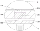
Preferably, the movable dust removing mechanism comprises a fixed block, the fixed block is fixedly connected to the bottom of the movable plate, a lead screw is rotatably connected to one side of the fixed block, which is far away from the support frame, a threaded block is in threaded connection with the surface of the lead screw, a movable block is fixedly connected to the bottom of the threaded block, a first bevel gear is fixedly connected to the right end of the lead screw, a second bevel gear is meshed with the outer ring of the first bevel gear, a transmission rod is fixedly connected to the top of the second bevel gear, a second motor is fixedly connected to the top of the transmission rod, a collection box is fixedly connected to the bottom of the movable block, a connecting pipe is fixedly connected to the bottom of the collection box, a dust collector is fixedly connected to the bottom of the connecting pipe, a transfer pipe is fixedly connected to the bottom of the dust collector, dust collecting pipes are fixedly connected to two sides of the transfer pipe, a dust collecting nozzle is fixedly connected to the bottom of the dust collecting pipe, and a bearing block is fixedly connected to the top of the support plate, and (4) carrying out centralized collection treatment on the scraps generated in the grinding process.
Preferably, the collecting box is fixedly connected to the top of the bearing block, the inner side of the bearing block is fixedly connected with the two sides of the dust collector, and the bearing block plays a role in supporting and fixing.
Preferably, the top of the threaded block is slidably connected with the bottom of the movable plate, the screw rod is movably connected to the right side of the support frame, the bottom of the second motor is fixedly connected with the top of the movable plate, the transmission rod is rotatably connected to the right side of the top of the movable plate, a through hole is formed in the top of the support plate, the inside of the through hole is fixedly connected with the surface of the dust collection pipe, and the transmission rod can better drive the screw rod to rotate through the first bevel gear, so that the dust collection pipe can better collect the chips.
Preferably, fixed establishment includes the support column, support column fixed connection is in the workstation top, the second spring has been cup jointed on the support column surface, the board is placed to second spring top fixedly connected with, support column top fixedly connected with limiting plate, limiting plate top fixedly connected with electric putter, electric putter keeps away from the tight piece of one end fixedly connected with clamp of support frame, place board top both sides and seted up the spout, can play fixed effect to the plywood, can not take place the skew at the in-process of polishing.
Preferably, second spring fixed connection is in the workstation top, press from both sides tight piece bottom and the inside sliding connection of spout, play a fixed effect to the tight piece of clamp, make that it can be better fix the plywood.
Preferably, place board sliding connection in the support frame inboard, place the board top and seted up the through-hole, the inside and support column surface sliding connection of through-hole, place the board and can play the effect that extrudees the second spring and play the buffering at the in-process of polishing.
Compared with the prior art, the invention provides a polishing device for a high-strength high-wear-resistance plywood, which has the following beneficial effects:
1. this high wear-resisting grinding device for plywood of high strength, through the grinding machanism who sets up, the piece of polishing receives when damaging at long-time polishing in-process, can be timely change the piece of polishing, and can not consume too much time at the in-process of dismantling, and it is comparatively convenient to use, and then reaches a quick effect of dismantling.
2. This high wear-resisting grinding device for plywood of high strength through the removal dust removal mechanism that sets up, can make the piece can not lead to the fact the influence to the environment on every side to the piece unified collection in the inside of collecting box that the in-process produced of polishing, also can not lead to the fact the injury to operating personnel, and then has also prolonged grinding device's life.
3. This high wear-resisting for plywood grinding device of high strength through the fixed establishment who sets up, plays the fixed effect of a centre gripping to the plywood that needs were polished, makes its in-process of polishing can not produce skew and dislocation, and does not need manual going to fix, has also saved staff's labour, and then reaches a good effect of polishing.
Drawings
In order to more clearly illustrate the technical solutions in the embodiments of the present invention, the drawings needed to be used in the description of the embodiments are briefly introduced below, and it is obvious that the drawings in the following description are only some embodiments of the present invention, and for those skilled in the art, other drawings can be obtained according to the drawings without inventive labor:
FIG. 1 is a front view of the structure of the present invention;
FIG. 2 is a front cross-sectional view of the structure of the present invention;
FIG. 3 is an enlarged schematic view of the structure at A in FIG. 2;
FIG. 4 is an enlarged view of the structure at B in FIG. 2;
fig. 5 is an enlarged schematic view of the structure at C in fig. 2.
In the figure: 1. a work table; 2. a support frame; 3. a hydraulic cylinder; 4. moving the plate; 5. a support plate; 6. a polishing mechanism; 601. a first motor; 602. a rotating rod; 603. grinding the sheets; 604. an L-shaped block; 605. a movable rod; 606. a stopper; 607. a first spring; 608. extruding the block; 609. a clamping block; 611. mounting blocks; 612. a support block; 7. a movable dust removal mechanism; 701. a fixed block; 702. a screw rod; 703. a thread block; 704. a first bevel gear; 705. a second bevel gear; 706. a second motor; 707. a moving block; 708. a collection box; 709. a connecting pipe; 711. a dust collector; 712. a transit tube; 713. a dust collection pipe; 714. a bearing block; 715. a dust suction nozzle; 716. a transmission rod; 8. a fixing mechanism; 801. a support pillar; 802. a second spring; 803. a limiting plate; 804. an electric push rod; 805. a clamping block; 806. placing a plate; 807. a chute.
Detailed Description
The technical solutions in the embodiments of the present invention will be clearly and completely described below with reference to the drawings in the embodiments of the present invention, and it is obvious that the described embodiments are only a part of the embodiments of the present invention, and not all of the embodiments. All other embodiments, which can be derived by a person skilled in the art from the embodiments given herein without making any creative effort, shall fall within the protection scope of the present invention.
In the present invention, unless otherwise expressly stated or limited, the terms "mounted," "connected," "secured," and the like are to be construed broadly and can, for example, be fixedly connected, detachably connected, or integrally formed; can be mechanically or electrically connected; either directly or indirectly through intervening media, either internally or in any other relationship. The specific meanings of the above terms in the present invention can be understood by those skilled in the art according to specific situations.
Referring to fig. 1-5, the present invention provides a technical solution: the utility model provides a high wear-resisting grinding device for plywood of high strength, includes workstation 1, 1 top fixedly connected with support frame 2 of workstation, 2 inboard bottom fixedly connected with hydraulic cylinder 3 of support frame, the one end fixedly connected with movable plate 4 of support frame 2 is kept away from to hydraulic cylinder 3, movable plate 4 and the inboard sliding connection of support frame, movable plate 4 bottom is provided with removal dust removal mechanism 7, remove dust removal mechanism 7 bottom and be provided with backup pad 5, backup pad 5 bottoms are provided with grinding machanism 6, 1 top of workstation is provided with fixed establishment 8.
The grinding mechanism 6 comprises a first motor 601, the first motor 601 is fixedly connected with the bottom of the support plate 5, the bottom of the first motor 601 is fixedly connected with a rotating rod 602, the bottom end of the rotating rod 602 is provided with a grinding plate 603, two sides of the rotating rod 602 are fixedly connected with L-shaped blocks 604, the outer sides of the L-shaped blocks 604 are movably connected with movable rods 605, the outer ends of the movable rods 605 are fixedly connected with a stop block 606, the inner ends of the movable rods 605 are fixedly connected with a squeezing block 608, the outer sides of the squeezing block 608 are fixedly connected with a first spring 607, one side of the stop block 606 close to the movable rods 605 is contacted with one side of the L-shaped blocks 604 far away from the rotating rod 602, the first spring 607 is sleeved on the surface of the movable rods 605, one end of the first spring 607 far away from the squeezing block 608 is fixedly connected with the inner side of the L-shaped blocks 604 to play a fixing role for the first spring 607, the inner side of the squeezing block 608 is fixedly connected with a clamping block 609, two sides of the rotating rod 602 are fixedly connected with a support block 612, and the top of the grinding plate 603 is fixedly connected with a mounting block 611, the bottom end of the rotating rod 602 is contacted with the top of the grinding piece 603, one side of the extrusion block 608, which is far away from the movable rod 605, is contacted with one side of the supporting block 612, which is far away from the rotating rod 602, the mounting block 611 is movably connected inside the supporting block 612, the clamping block 609 is movably connected inside the mounting block 611, the clamping groove is formed inside the supporting block 612, the inside of the clamping groove is movably connected with the surface of the clamping block 609, and the clamping block 609 has a limiting effect on the mounting block 611, so that the grinding piece 603 can be mounted at the bottom end of the rotating rod 602.
The movable dust removing mechanism 7 comprises a fixed block 701, the fixed block 701 is fixedly connected to the bottom of the movable plate 4, one side of the fixed block 701, which is far away from the support frame 2, is rotatably connected with a screw rod 702, a thread block 703 is in threaded connection with the surface of the screw rod 702, a movable block 707 is fixedly connected to the bottom of the thread block 703, the right end of the screw rod 702 is fixedly connected with a first bevel gear 704, a second bevel gear 705 is meshed with the outer ring of the first bevel gear 704, a transmission rod 716 is fixedly connected to the top of the second bevel gear 705, a second motor 706 is fixedly connected to the top of the transmission rod 716, a collection box 708 is fixedly connected to the bottom of the movable block 707, a connection pipe 709 is fixedly connected to the bottom of the collection box 708, a dust collector 711 is fixedly connected to the bottom of the connection pipe 711 is fixedly connected to the bottom of the dust collector 711, dust collection pipes 713 are fixedly connected to two sides of the transfer pipe 712, a dust collection nozzle 715 is fixedly connected to the bottom of the dust collection pipe 713, and the top of the thread block 703 is slidably connected to the bottom of the movable plate 4, screw 702 swing joint is on the support frame 2 right side, second motor 706 bottom and movable plate 4 top fixed connection, transfer link 716 rotates to be connected in movable plate 4 top right side, the through hole has been seted up at backup pad 5 top, the inside and dust absorption pipe 713 surface fixed connection of through hole, transfer link 716 can be better drives screw 702 through first bevel gear 704 and rotates, make dust absorption pipe 713 can be to the better collection of piece, backup pad 5 top fixedly connected with bearing block 714, carry out the centralized collection processing to the piece that produces the in-process of polishing, collecting box 708 fixed connection is at bearing block 714 top, the inboard and dust catcher 711 both sides fixed connection of bearing block 714, bearing block 714 plays the fixed effect of support.
The fixing mechanism 8 comprises a supporting column 801, the supporting column 801 is fixedly connected to the top of the workbench 1, a second spring 802 is sleeved on the surface of the supporting column 801, a placing plate 806 is fixedly connected to the top end of the second spring 802, the placing plate 806 is slidably connected to the inner side of the supporting frame 2, a through hole is formed in the top of the placing plate 806, the inside of the through hole is slidably connected with the surface of the supporting column 801, the placing plate 806 can extrude the second spring 802 to play a buffering role in the polishing process, a limiting plate 803 is fixedly connected to the top end of the supporting column 801, an electric push rod 804 is fixedly connected to the top end of the limiting plate 803, a clamping block 805 is fixedly connected to one end, far away from the supporting frame 2, of the electric push rod 804, sliding grooves 807 are formed in two sides of the top of the placing plate 806, the plywood can be fixed, deviation cannot occur in the polishing process, the second spring 802 is fixedly connected to the top of the workbench 1, the bottom of the clamping block 805 is slidably connected with the inside of the sliding grooves 807, the clamping block 805 is provided with a fixing function, so that plywood can be better fixed.
In practical operation, when the device is used and the polishing sheet 603 needs to be replaced, the stop 606 is pulled at the same time, the movable rod 605 drives the pressing block 608 to move out of the mounting block 611 and the supporting block 612, so that the mounting block 611 can be pulled out of the supporting block 612, and the polishing sheet 603 drives the mounting block 611 to move downwards due to the gravity, so that the polishing sheet 603 is detached.
When the plywood needs to be fixed, the electric push rod 804 is started at first, the clamping blocks 805 are driven to move towards the direction close to the support frame 2, then the plywood is placed on the inner sides of the two clamping blocks 805, then the electric push rod 804 is started again, the clamping blocks 805 are driven to move towards the direction far away from the support frame 2, and the plywood is clamped and fixed.
When the plywood needs to be polished, the hydraulic cylinder 3 is started firstly to drive the moving plate 4 to move downwards, so that the polishing piece 603 can contact the plywood, at this time, the first motor 601 is started to drive the polishing disc 603 to rotate through the rotating rod 602, so as to polish the plywood, and at the same time, the dust collector 711 is started, and the dust collector 711 sucks the debris generated in the grinding process into the collection box 708 through the transit pipe 712, the dust collection pipe 713 and the dust collection nozzle 715, so that the collection of the debris is completed, then the second motor 706 is started again, the second bevel gear 705 is driven by the transmission rod 716, the first bevel gear 704 and the screw rod 702 rotate, the screw rod 702 drives the thread block 703 to move in the rotating process, the second motor 706 rotates in a reciprocating manner, and then drive the piece 603 of polishing of bottommost through lead screw 702 and also do reciprocating motion, and then realize polishing the plywood.
It is noted that, herein, relational terms such as first and second, and the like may be used solely to distinguish one entity or action from another entity or action without necessarily requiring or implying any actual such relationship or order between such entities or actions. Also, the terms "comprises," "comprising," or any other variation thereof, are intended to cover a non-exclusive inclusion, such that a process, method, article, or apparatus that comprises a list of elements does not include only those elements but may include other elements not expressly listed or inherent to such process, method, article, or apparatus. Without further limitation, an element described by the phrase "comprising a. -" does not exclude the presence of other identical elements in a process, method, article, or apparatus that comprises the element.
Claims (9)
1. The utility model provides a high wear-resisting grinding device for plywood of high strength, includes workstation (1), its characterized in that: the top of the workbench (1) is fixedly connected with a support frame (2), the bottom of the inner side of the support frame (2) is fixedly connected with a hydraulic cylinder (3), one end, far away from the support frame (2), of the hydraulic cylinder (3) is fixedly connected with a movable plate (4), the movable plate (4) is in sliding connection with the inner side of the support frame (2), the bottom of the movable plate (4) is provided with a movable dust removal mechanism (7), the bottom of the movable dust removal mechanism (7) is provided with a support plate (5), the bottom of the support plate (5) is provided with a polishing mechanism (6), and the top of the workbench (1) is provided with a fixing mechanism (8);
the grinding mechanism (6) comprises a first motor (601), the first motor (601) is fixedly connected to the bottom of the supporting plate (5), the bottom of the first motor (601) is fixedly connected with a rotating rod (602), the bottom end of the rotating rod (602) is provided with a polishing disc (603), two sides of the rotating rod (602) are fixedly connected with L-shaped blocks (604), the outer sides of the L-shaped blocks (604) are movably connected with movable rods (605), the outer end of the movable rod (605) is fixedly connected with a stop block (606), the inner end of the movable rod (605) is fixedly connected with an extrusion block (608), a first spring (607) is fixedly connected with the outer side of the extrusion block (608), a clamping block (609) is fixedly connected with the inner side of the extrusion block (608), supporting blocks (612) are fixedly connected to two sides of the rotating rod (602), and mounting blocks (611) are fixedly connected to the tops of the polishing sheets (603).
2. The grinding device for the high-strength and high-wear-resistance plywood as claimed in claim 1, wherein: one side of the stop block (606) close to the movable rod (605) is in contact with one side of the L-shaped block (604) far away from the rotating rod (602), the first spring (607) is sleeved on the surface of the movable rod (605), and one end of the first spring (607) far away from the extrusion block (608) is fixedly connected with the inner side of the L-shaped block (604).
3. The grinding device for the high-strength and high-wear-resistance plywood as claimed in claim 1, wherein: the bottom end of the rotating rod (602) is in contact with the top of the polishing plate (603), one side, away from the movable rod (605), of the extrusion block (608) is in contact with one side, away from the rotating rod (602), of the supporting block (612), the installation block (611) is movably connected inside the supporting block (612), the clamping block (609) is movably connected inside the installation block (611), a clamping groove is formed inside the supporting block (612), and the inside of the clamping groove is movably connected with the surface of the clamping block (609).
4. The grinding device for the high-strength and high-wear-resistance plywood as claimed in claim 1, wherein: the movable dust removing mechanism (7) comprises a fixed block (701), the fixed block (701) is fixedly connected to the bottom of the movable plate (4), one side, away from the support frame (2), of the fixed block (701) is rotatably connected with a lead screw (702), a thread block (703) is in threaded connection with the surface of the lead screw (702), a movable block (707) is fixedly connected to the bottom of the thread block (703), a first bevel gear (704) is fixedly connected to the right end of the lead screw (702), a second bevel gear (705) is meshed with the outer ring of the first bevel gear (704), a transmission rod (716) is fixedly connected to the top of the second bevel gear (705), a second motor (706) is fixedly connected to the top of the transmission rod (716), a collecting box (708) is fixedly connected to the bottom of the movable block (707), a connecting pipe (709) is fixedly connected to the bottom of the collecting box (708), and a dust suction machine (711), the dust collector (711) bottom fixedly connected with transfer pipe (712), transfer pipe (712) both sides fixedly connected with dust absorption pipe (713), dust absorption pipe (713) bottom fixedly connected with dust absorption nozzle (715), backup pad (5) top fixedly connected with bearing block (714).
5. The grinding device for the high-strength and high-wear-resistance plywood as claimed in claim 4, wherein: the collecting box (708) is fixedly connected to the top of the bearing block (714), and the inner side of the bearing block (714) is fixedly connected with the two sides of the dust collector (711).
6. The grinding device for the high-strength and high-wear-resistance plywood as claimed in claim 4, wherein: the top of the thread block (703) is connected with the bottom of the moving plate (4) in a sliding mode, the screw rod (702) is movably connected to the right side of the support frame (2), the bottom of the second motor (706) is fixedly connected with the top of the moving plate (4), the transmission rod (716) is rotatably connected to the right side of the top of the moving plate (4), a through hole is formed in the top of the support plate (5), and the inside of the through hole is fixedly connected with the surface of the dust collection pipe (713).
7. The grinding device for the high-strength and high-wear-resistance plywood as claimed in claim 1, wherein: fixed establishment (8) include support column (801), support column (801) fixed connection is in workstation (1) top, second spring (802) have been cup jointed on support column (801) surface, board (806) are placed to second spring (802) top fixedly connected with, support column (801) top fixedly connected with limiting plate (803), limiting plate (803) top fixedly connected with electric putter (804), electric putter (804) are kept away from the one end fixedly connected with of support frame (2) and are pressed from both sides tight piece (805), place board (806) top both sides and seted up spout (807).
8. The grinding device for the high-strength and high-wear-resistance plywood as claimed in claim 7, wherein: the second spring (802) is fixedly connected to the top of the workbench (1), and the bottom of the clamping block (805) is in sliding connection with the inside of the sliding groove (807).
9. The grinding device for the high-strength and high-wear-resistance plywood as claimed in claim 7, wherein: the placing plate (806) is connected to the inner side of the support frame (2) in a sliding mode, a through hole is formed in the top of the placing plate (806), and the inner portion of the through hole is connected with the surface of the support column (801) in a sliding mode.
Priority Applications (1)
| Application Number | Priority Date | Filing Date | Title |
|---|---|---|---|
| CN202210281077.5A CN114932468A (en) | 2022-03-21 | 2022-03-21 | High wear-resisting grinding device for plywood of high strength |
Applications Claiming Priority (1)
| Application Number | Priority Date | Filing Date | Title |
|---|---|---|---|
| CN202210281077.5A CN114932468A (en) | 2022-03-21 | 2022-03-21 | High wear-resisting grinding device for plywood of high strength |
Publications (1)
| Publication Number | Publication Date |
|---|---|
| CN114932468A true CN114932468A (en) | 2022-08-23 |
Family
ID=82862351
Family Applications (1)
| Application Number | Title | Priority Date | Filing Date |
|---|---|---|---|
| CN202210281077.5A Pending CN114932468A (en) | 2022-03-21 | 2022-03-21 | High wear-resisting grinding device for plywood of high strength |
Country Status (1)
| Country | Link |
|---|---|
| CN (1) | CN114932468A (en) |
Cited By (1)
| Publication number | Priority date | Publication date | Assignee | Title |
|---|---|---|---|---|
| CN116765983A (en) * | 2023-08-24 | 2023-09-19 | 江苏鑫亿船舶装饰工程有限公司 | Plate flat grinding device with coating treatment for furniture production |
Citations (23)
| Publication number | Priority date | Publication date | Assignee | Title |
|---|---|---|---|---|
| CN208428062U (en) * | 2018-05-28 | 2019-01-25 | 盐城赛威电子科技有限公司 | A kind of mobile phone shell burr remover |
| CN208629232U (en) * | 2018-04-12 | 2019-03-22 | 大连守信轮胎翻新有限公司 | A kind of giant tire refurbishment grinding equipment |
| CN209062718U (en) * | 2018-10-16 | 2019-07-05 | 天津兴耀金属制品有限公司 | A kind of stainless steel wire pill cutting rounding machine |
| CN209850613U (en) * | 2019-05-22 | 2019-12-27 | 厦门荧烁工业模型设计有限公司 | Polishing device is used in production of beauty instrument model |
| CN111168512A (en) * | 2020-01-15 | 2020-05-19 | 陈美和 | Grinding device for valve machining and using method thereof |
| CN210790326U (en) * | 2019-10-25 | 2020-06-19 | 国林(东莞)螺丝制品有限公司 | Edging device is used in screw production |
| CN211465712U (en) * | 2019-12-30 | 2020-09-11 | 江苏安惠环境设备科技有限公司 | Grinding device is used in stainless steel processing convenient to it is spacing |
| CN111805363A (en) * | 2020-08-06 | 2020-10-23 | 肖叶 | Grinding device for crystal processing |
| CN211890341U (en) * | 2020-09-29 | 2020-11-10 | 广东众信工业设计有限公司 | Cutting machine convenient to change emery wheel |
| CN212071428U (en) * | 2020-05-14 | 2020-12-04 | 南通万岭机械有限公司 | Train bearing grinding device |
| CN212496902U (en) * | 2020-05-21 | 2021-02-09 | 深圳市天瑞祥宇电子有限公司 | A edging equipment for circuit board |
| CN212496893U (en) * | 2020-05-27 | 2021-02-09 | 泗阳恒远木业有限公司 | Grinding device is used in plywood processing |
| CN212496925U (en) * | 2020-04-28 | 2021-02-09 | 重庆秉穗科技有限公司 | Polishing device for welding robot |
| CN212762516U (en) * | 2020-08-13 | 2021-03-23 | 甘翠 | Subway vehicle body part grinding device |
| CN213004470U (en) * | 2020-05-28 | 2021-04-20 | 昆山独角兽机器人有限公司 | A manipulator structure for polishing mould |
| CN213438686U (en) * | 2020-11-03 | 2021-06-15 | 漳州市佳茂钢管家具有限公司 | Numerical control grinding device for bench surface |
| CN213673363U (en) * | 2020-11-11 | 2021-07-13 | 江苏月兴五金电器有限公司 | Grinding device for processing dry-type multi-disc electromagnetic clutch |
| CN213889313U (en) * | 2020-12-21 | 2021-08-06 | 江苏塞米门窗科技有限公司 | Aluminum alloy burnishing device is used in aluminum alloy door and window processing |
| CN213917385U (en) * | 2020-12-02 | 2021-08-10 | 黄瑞生 | Plate polishing equipment |
| CN214771078U (en) * | 2021-05-25 | 2021-11-19 | 泰州领晟电子科技有限公司 | Electric connector shell equipment of polishing |
| CN214869528U (en) * | 2021-05-29 | 2021-11-26 | 杭州雅尚造型艺术有限公司 | Novel sculpture polishing device |
| CN214979755U (en) * | 2021-03-01 | 2021-12-03 | 立邦(福建)滤清器制造有限公司 | End surface grinding device for filter machining |
| CN215394235U (en) * | 2021-07-22 | 2022-01-04 | 深圳市鸿运鑫精密工业有限公司 | Grinding device for plywood |
-
2022
- 2022-03-21 CN CN202210281077.5A patent/CN114932468A/en active Pending
Patent Citations (23)
| Publication number | Priority date | Publication date | Assignee | Title |
|---|---|---|---|---|
| CN208629232U (en) * | 2018-04-12 | 2019-03-22 | 大连守信轮胎翻新有限公司 | A kind of giant tire refurbishment grinding equipment |
| CN208428062U (en) * | 2018-05-28 | 2019-01-25 | 盐城赛威电子科技有限公司 | A kind of mobile phone shell burr remover |
| CN209062718U (en) * | 2018-10-16 | 2019-07-05 | 天津兴耀金属制品有限公司 | A kind of stainless steel wire pill cutting rounding machine |
| CN209850613U (en) * | 2019-05-22 | 2019-12-27 | 厦门荧烁工业模型设计有限公司 | Polishing device is used in production of beauty instrument model |
| CN210790326U (en) * | 2019-10-25 | 2020-06-19 | 国林(东莞)螺丝制品有限公司 | Edging device is used in screw production |
| CN211465712U (en) * | 2019-12-30 | 2020-09-11 | 江苏安惠环境设备科技有限公司 | Grinding device is used in stainless steel processing convenient to it is spacing |
| CN111168512A (en) * | 2020-01-15 | 2020-05-19 | 陈美和 | Grinding device for valve machining and using method thereof |
| CN212496925U (en) * | 2020-04-28 | 2021-02-09 | 重庆秉穗科技有限公司 | Polishing device for welding robot |
| CN212071428U (en) * | 2020-05-14 | 2020-12-04 | 南通万岭机械有限公司 | Train bearing grinding device |
| CN212496902U (en) * | 2020-05-21 | 2021-02-09 | 深圳市天瑞祥宇电子有限公司 | A edging equipment for circuit board |
| CN212496893U (en) * | 2020-05-27 | 2021-02-09 | 泗阳恒远木业有限公司 | Grinding device is used in plywood processing |
| CN213004470U (en) * | 2020-05-28 | 2021-04-20 | 昆山独角兽机器人有限公司 | A manipulator structure for polishing mould |
| CN111805363A (en) * | 2020-08-06 | 2020-10-23 | 肖叶 | Grinding device for crystal processing |
| CN212762516U (en) * | 2020-08-13 | 2021-03-23 | 甘翠 | Subway vehicle body part grinding device |
| CN211890341U (en) * | 2020-09-29 | 2020-11-10 | 广东众信工业设计有限公司 | Cutting machine convenient to change emery wheel |
| CN213438686U (en) * | 2020-11-03 | 2021-06-15 | 漳州市佳茂钢管家具有限公司 | Numerical control grinding device for bench surface |
| CN213673363U (en) * | 2020-11-11 | 2021-07-13 | 江苏月兴五金电器有限公司 | Grinding device for processing dry-type multi-disc electromagnetic clutch |
| CN213917385U (en) * | 2020-12-02 | 2021-08-10 | 黄瑞生 | Plate polishing equipment |
| CN213889313U (en) * | 2020-12-21 | 2021-08-06 | 江苏塞米门窗科技有限公司 | Aluminum alloy burnishing device is used in aluminum alloy door and window processing |
| CN214979755U (en) * | 2021-03-01 | 2021-12-03 | 立邦(福建)滤清器制造有限公司 | End surface grinding device for filter machining |
| CN214771078U (en) * | 2021-05-25 | 2021-11-19 | 泰州领晟电子科技有限公司 | Electric connector shell equipment of polishing |
| CN214869528U (en) * | 2021-05-29 | 2021-11-26 | 杭州雅尚造型艺术有限公司 | Novel sculpture polishing device |
| CN215394235U (en) * | 2021-07-22 | 2022-01-04 | 深圳市鸿运鑫精密工业有限公司 | Grinding device for plywood |
Cited By (2)
| Publication number | Priority date | Publication date | Assignee | Title |
|---|---|---|---|---|
| CN116765983A (en) * | 2023-08-24 | 2023-09-19 | 江苏鑫亿船舶装饰工程有限公司 | Plate flat grinding device with coating treatment for furniture production |
| CN116765983B (en) * | 2023-08-24 | 2023-11-03 | 江苏鑫亿船舶装饰工程有限公司 | Plate flat grinding device with coating treatment for furniture production |
Similar Documents
| Publication | Publication Date | Title |
|---|---|---|
| CN109591121B (en) | Cutting and polishing integrated equipment for poplar processing | |
| CN110922041B (en) | Self-suction float glass cutting device | |
| CN211805291U (en) | Adjustable fiberboard edge grinding device | |
| CN114932468A (en) | High wear-resisting grinding device for plywood of high strength | |
| CN213267290U (en) | Can move device of tailorring of back of body adhesive tape | |
| CN209223425U (en) | A kind of absorption type laser processing device | |
| CN216066930U (en) | Burnishing machine is used in stone material processing that simple operation and work efficiency are high | |
| CN212266012U (en) | Cutting device is used in lens production | |
| CN211566217U (en) | Cold press | |
| CN212497305U (en) | Grinding wheel cutting device with dust removal function | |
| CN212496893U (en) | Grinding device is used in plywood processing | |
| CN214135292U (en) | Equipment tool for automatically polishing and deburring copper plate | |
| CN114523521A (en) | Wood board punching device for civil construction and use method thereof | |
| CN211590271U (en) | Building board cutting device convenient to collect waste material | |
| CN218314128U (en) | Wood dust removal device | |
| CN220346340U (en) | A cementing machine for optical lens production | |
| CN211057140U (en) | Cutting dust collector is used in leather processing | |
| CN216327256U (en) | Part polishing and polishing machine for machining | |
| CN110883640A (en) | Timber deckle edge remove device for furniture production | |
| CN220486132U (en) | Plain weave cloth cutting device | |
| CN214213359U (en) | Burnishing device is used in metal product production | |
| CN219336139U (en) | Special-shaped section bar cuts vanning equipment convenient to it is clean | |
| CN218927254U (en) | Side polishing device for hollow glass | |
| CN218504765U (en) | Cutting device with movable slide rail | |
| CN213702838U (en) | Garbage bin surface grinding device |
Legal Events
| Date | Code | Title | Description |
|---|---|---|---|
| PB01 | Publication | ||
| PB01 | Publication | ||
| SE01 | Entry into force of request for substantive examination | ||
| SE01 | Entry into force of request for substantive examination |