CN210790326U - An edge grinding device for screw production - Google Patents
An edge grinding device for screw production Download PDFInfo
- Publication number
- CN210790326U CN210790326U CN201921808735.1U CN201921808735U CN210790326U CN 210790326 U CN210790326 U CN 210790326U CN 201921808735 U CN201921808735 U CN 201921808735U CN 210790326 U CN210790326 U CN 210790326U
- Authority
- CN
- China
- Prior art keywords
- fixed
- wall
- locking
- welded fastening
- block
- Prior art date
- Legal status (The legal status is an assumption and is not a legal conclusion. Google has not performed a legal analysis and makes no representation as to the accuracy of the status listed.)
- Expired - Fee Related
Links
Images



Landscapes
- Finish Polishing, Edge Sharpening, And Grinding By Specific Grinding Devices (AREA)
- Grinding-Machine Dressing And Accessory Apparatuses (AREA)
Abstract
Description
技术领域technical field
本实用新型属于螺丝生产设备技术领域,具体涉及一种螺丝生产用磨边装置。The utility model belongs to the technical field of screw production equipment, in particular to an edge grinding device for screw production.
背景技术Background technique
常规的螺丝加工脱模后一般都需要将周边的毛边做切除片处理,使其表面光滑,一般采用铣床进行毛边打磨,而且对于螺丝这种小型件来说,采用铣刀打磨时不仅麻烦,同时铣刀或者待加工件在移动的过程中需要配备有能够可靠固定螺丝的固定台,否则在切割过程中一旦待加工螺丝发生位移,则会造成铣刀等零部件损坏,以及产品报废。但是现有的打磨设备在打磨过程中不能确保螺丝在加工的过程中不会出现晃动、偏移等状况,而且不方便对打磨块进行拆卸更换,从而影响磨边效果。After the conventional screw processing and demoulding, it is generally necessary to cut off the surrounding burrs to make the surface smooth. Generally, a milling machine is used for burr grinding, and for small parts such as screws, it is not only troublesome to use a milling cutter to grind at the same time. The milling cutter or the workpiece to be processed needs to be equipped with a fixing table that can reliably fix the screw during the movement. Otherwise, once the screw to be processed is displaced during the cutting process, the milling cutter and other components will be damaged, and the product will be scrapped. However, the existing grinding equipment cannot ensure that the screws will not shake or shift during the grinding process, and it is inconvenient to disassemble and replace the grinding block, thereby affecting the edging effect.
因此针对这一现状,迫切需要设计和生产一种螺丝生产用磨边装置,以满足实际使用的需要。Therefore, in view of this situation, it is urgent to design and produce an edge grinding device for screw production to meet the needs of practical use.
实用新型内容Utility model content
本实用新型的目的在于提供一种螺丝生产用磨边装置,以解决上述背景技术中提出的问题。The purpose of the present invention is to provide an edge grinding device for screw production, so as to solve the problems raised in the above-mentioned background technology.
为实现上述目的,本实用新型提供如下技术方案:一种螺丝生产用磨边装置,包括操作箱、驱动装置、固定装置和打磨装置,所述操作箱的右侧外壁上设有驱动装置,所述操作箱的底板表面焊接固定有支撑板,所述支撑板内通过轴承转动连接有转动杆,所述转动杆的外壁上焊接固定有从动转盘,所述转动杆的左端面上焊接固定有固定装置,所述操作箱的左侧内壁上通过螺栓固定有电动伸缩杆一,所述电动伸缩杆一的伸缩端焊接固定有固定板,所述固定板的右侧外壁上通过连接杆焊接固定有固定块一,所述固定块一内安装有磁块,所述操作箱内焊接固定有调节螺杆,所述调节螺杆的外壁上滑动连接有打磨装置,所述操作箱的顶部通过螺栓固定有抽风机,所述抽风机通过出风管连接有集尘箱。In order to achieve the above purpose, the utility model provides the following technical solutions: an edge grinding device for screw production, comprising an operation box, a driving device, a fixing device and a grinding device, and the right outer wall of the operation box is provided with a driving device, so A support plate is welded and fixed on the surface of the bottom plate of the operation box, a rotating rod is rotatably connected to the support plate through a bearing, a driven turntable is welded and fixed on the outer wall of the rotating rod, and a left end surface of the rotating rod is welded and fixed with Fixing device, an electric
优选的,所述驱动装置包括电机箱和旋转电机,所述电机箱通过螺栓固定在操作箱的右侧外壁,所述电机箱内通过螺栓固定有旋转电机,所述旋转电机的输出端焊接固定有旋转轴,所述旋转轴延伸至操作箱内且旋转轴的外壁上焊接固定有主动转盘。Preferably, the drive device includes a motor box and a rotary motor, the motor box is fixed on the right outer wall of the operation box by bolts, a rotary motor is fixed in the motor box by bolts, and the output end of the rotary motor is fixed by welding There is a rotating shaft, the rotating shaft extends into the operation box, and an active turntable is welded and fixed on the outer wall of the rotating shaft.
优选的,所述固定装置包括固定块二和夹板,所述固定块二内开设有固定槽,所述固定块二的顶部和底部开设有通孔,通孔内滑动连接有固定杆,所述固定杆的一端焊接固定有夹板,另一端焊接固定有调节环,所述固定杆的外壁上套设有固定弹簧。Preferably, the fixing device includes a second fixing block and a splint, a fixing groove is formed in the second fixing block, a through hole is formed at the top and the bottom of the second fixing block, and a fixing rod is slidably connected in the through hole. One end of the fixing rod is welded and fixed with a splint, and the other end is welded and fixed with an adjusting ring, and a fixing spring is sleeved on the outer wall of the fixing rod.
优选的,所述打磨装置包括安装板和固定套筒,所述安装板上开设有另一组通孔,所述安装板通过通孔在调节螺杆上滑动,所述安装板的一侧通过螺栓固定有电动伸缩杆二,所述电动伸缩杆二的伸缩端焊接固定有固定套筒,所述固定套筒的两侧外壁上焊接固定有锁定装置,所述固定套筒内通过锁定装置固定有连接块,所述连接块的一侧通过螺栓固定有打磨块。Preferably, the grinding device includes a mounting plate and a fixing sleeve, the mounting plate is provided with another group of through holes, the mounting plate slides on the adjusting screw through the through holes, and one side of the mounting plate passes through the bolts The second electric telescopic rod is fixed, the telescopic end of the second electric telescopic rod is welded and fixed with a fixed sleeve, the outer walls of both sides of the fixed sleeve are welded and fixed with locking devices, and the fixed sleeve is fixed by the locking device. A connecting block, one side of the connecting block is fixed with a grinding block by bolts.
优选的,所述锁定装置包括锁定套筒和锁定柱,所述锁定套筒焊接固定在固定套筒的外壁上,所述连接块的两侧外壁上开设有锁定孔,所述锁定柱贯穿锁定套筒,并延伸至连接块上的锁定孔内,所述锁定柱的外壁上焊接固定有导向板,导向板的一侧焊接固定有支撑弹簧,所述支撑弹簧的另一端与锁定套筒焊接固定。Preferably, the locking device includes a locking sleeve and a locking column, the locking sleeve is welded and fixed on the outer wall of the fixing sleeve, the outer walls on both sides of the connecting block are provided with locking holes, and the locking column penetrates through the locking hole. A guide plate is welded and fixed on the outer wall of the locking column, a support spring is welded and fixed on one side of the guide plate, and the other end of the support spring is welded with the locking sleeve fixed.
优选的,所述抽风机的进气管延伸至操作箱内,并焊接固定有风罩,所述集尘箱的顶板上开设有多组通气孔。Preferably, the air intake pipe of the exhaust fan extends into the operation box, and a hood is welded and fixed, and a plurality of sets of ventilation holes are provided on the top plate of the dust collecting box.
本实用新型的技术效果和优点:该螺丝生产用磨边装置,通过固定装置能够将螺丝的一端进行固定,通过固定块二上的磁块能够将螺丝的另一端进行固定,保证在打磨过程中螺丝不会产生偏移,提高了打磨效果;通过锁定装置能够将连接块和打磨块固定在固定套筒内,通过向外拉动锁定装置上的锁定杆,能够使连接块与固定套筒分离,更加方便的对打磨块进行更换;通过抽风机能够将打磨产生的粉尘吸附进集尘箱内,避免粉尘碎屑落入操作箱,降低操作箱的清洁难度,该螺丝生产用磨边装置,不仅能够对不同规格的螺丝进行打磨,还能够对打磨产生的粉尘进行有效的吸附。The technical effects and advantages of the present utility model: the edging device used for screw production can fix one end of the screw through the fixing device, and fix the other end of the screw through the magnetic block on the second fixing block, so as to ensure that during the grinding process The screw will not be offset, which improves the grinding effect; the connecting block and the grinding block can be fixed in the fixed sleeve through the locking device, and the connecting block can be separated from the fixed sleeve by pulling the locking rod on the locking device outwards. It is more convenient to replace the grinding block; the dust generated by grinding can be absorbed into the dust collecting box by the exhaust fan, so as to prevent dust debris from falling into the operation box, and reduce the difficulty of cleaning the operation box. The screw production edge grinding device, not only It can grind screws of different specifications, and can effectively absorb the dust generated by grinding.
附图说明Description of drawings
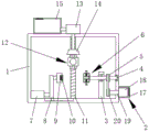
图1为本实用新型的主视图;Fig. 1 is the front view of the utility model;
图2为本实用新型的剖视图;Fig. 2 is the sectional view of the utility model;
图3为本实用新型的固定装置的剖视图;3 is a cross-sectional view of the fixing device of the present invention;
图4为本实用新型的打磨装置的横向剖视图;Fig. 4 is the transverse sectional view of the grinding device of the present invention;
图5为本实用新型的锁定装置的剖视图。5 is a cross-sectional view of the locking device of the present invention.
图中:1操作箱、2驱动装置、3支撑板、4转动杆、5从动转盘、6固定装置、7电动伸缩杆一、8固定板、9固定块一、10磁块、11调节螺杆、12打磨装置、13抽风机、14风罩、15集尘箱、16锁定装置、17电机箱、18旋转电机、19旋转轴、20主动转盘、21固定块二、22固定杆、23夹板、24固定弹簧、25安装板、26电动伸缩杆二、27固定套筒、28连接块、29打磨块、30锁定套筒、31锁定柱、32支撑弹簧。In the picture: 1 operation box, 2 driving device, 3 supporting plate, 4 rotating rod, 5 driven turntable, 6 fixing device, 7 electric
具体实施方式Detailed ways
下面将结合本实用新型实施例中的附图,对本实用新型实施例中的技术方案进行清楚、完整地描述,显然,所描述的实施例仅仅是本实用新型一部分实施例,而不是全部的实施例。基于本实用新型中的实施例,本领域普通技术人员在没有做出创造性劳动前提下所获得的所有其他实施例,都属于本实用新型保护的范围。The technical solutions in the embodiments of the present utility model will be clearly and completely described below with reference to the accompanying drawings in the embodiments of the present utility model. Obviously, the described embodiments are only a part of the embodiments of the present utility model, rather than all the implementations. example. Based on the embodiments of the present invention, all other embodiments obtained by those of ordinary skill in the art without creative work fall within the protection scope of the present invention.
除非单独定义指出的方向外,本文涉及的上、下、左、右、前、后等方向均是以本实用新型所示的图中的上、下、左、右、前、后等方向为准,在此一并说明。Except for the directions indicated by the individual definitions, the directions of up, down, left, right, front, back, etc. involved in this document are the directions of up, down, left, right, front, back, etc. in the figures shown in the present utility model. Yes, it will be explained here.
本实用新型提供了如图1-5所示的一种螺丝生产用磨边装置,包括操作箱1、驱动装置2、固定装置6和打磨装置12,所述操作箱1的右侧外壁上设有驱动装置2,所述操作箱1的底板表面焊接固定有支撑板3,所述支撑板3内通过轴承转动连接有转动杆4,所述转动杆4的外壁上焊接固定有从动转盘5,所述转动杆4的左端面上焊接固定有固定装置6,所述转动杆4的通过另一组轴承与操作箱1的右侧内壁转动连接,所述操作箱1的左侧内壁上通过螺栓固定有电动伸缩杆一7,所述电动伸缩杆一7的型号为:TGA-200,所述电动伸缩杆一7的伸缩端焊接固定有固定板8,所述操作箱1的底部表面开设有滑槽,所述固定板8通过滑块在滑槽内移动,所述固定板8的右侧外壁上通过连接杆焊接固定有固定块一9,所述固定块一9内安装有磁块10,所述操作箱1内焊接固定有调节螺杆11,所述调节螺杆11的外壁上滑动连接有打磨装置12,所述打磨装置12上下两侧的调节螺杆11的外壁上螺纹连接固定螺母,通过固定螺母能够对打磨装置12在调节螺杆11上位置进行调整和固定,所述操作箱1的顶部通过螺栓固定有抽风机13,所述抽风机13的型号为:RB-73D-1,所述抽风机13通过出风管连接有集尘箱15,所述操作箱1和集尘箱15上均通过铰链铰接有箱门,箱门上通过螺栓固定有把手。The utility model provides an edge grinding device for screw production as shown in Figures 1-5, comprising an
具体的,所述驱动装置2包括电机箱17和旋转电机18,所述电机箱17通过螺栓固定在操作箱1的右侧外壁,所述电机箱17内通过螺栓固定有旋转电机18,所述旋转电机18的型号为:86BYG120,所述旋转电机18的输出端焊接固定有旋转轴19,所述旋转轴19延伸至操作箱1内且旋转轴19的外壁上焊接固定有主动转盘20,所述主动转盘20与从动转盘5通过皮带转动连接。Specifically, the
具体的,所述固定装置6包括固定块二21和夹板23,所述固定块二21内开设有固定槽,所述固定块二21的顶部和底部开设有通孔,通孔内滑动连接有固定杆22,所述固定杆22的一端焊接固定有夹板23,另一端焊接固定有调节环,所述固定杆22的外壁上套设有固定弹簧24,通过调整两组夹板23之间的距离,能够对不同规格的螺丝进行固定。Specifically, the
具体的,所述打磨装置12包括安装板25和固定套筒27,所述安装板25上开设有另一组通孔,所述安装板25通过通孔在调节螺杆11上滑动,所述安装板25的一侧通过螺栓固定有电动伸缩杆二26,所述电动伸缩杆二26的型号为:TGA-200,所述电动伸缩杆二26的伸缩端焊接固定有固定套筒27,所述固定套筒27的两侧外壁上焊接固定有锁定装置16,所述固定套筒27内通过锁定装置16固定有连接块28,所述连接块28的一侧通过螺栓固定有打磨块29。Specifically, the
具体的,所述锁定装置16包括锁定套筒30和锁定柱31,所述锁定套筒30焊接固定在固定套筒27的外壁上,所述连接块28的两侧外壁上开设有锁定孔,所述锁定柱31贯穿锁定套筒30,并延伸至连接块28上的锁定孔内,所述锁定柱31的外壁上焊接固定有导向板,导向板的一侧焊接固定有支撑弹簧32,所述支撑弹簧32的另一端与锁定套筒30焊接固定,通过拉动锁定柱31,使锁定柱31与连接块分离,便于连接块28和打磨块29的安装和拆卸。Specifically, the
具体的,所述抽风机13的进气管延伸至操作箱1内,并焊接固定有风罩14,所述集尘箱15的顶板上开设有多组通气孔,通气孔下方的集尘箱15顶板上通过螺栓固定有防尘网。Specifically, the air intake pipe of the
具体的,该螺丝生产用磨边装置,在使用时,将螺丝的平头端放在固定块二21内,向外拉动固定杆22带动夹板23移动,将螺丝的平头端固定在两组夹板23之间,通过电动伸缩杆一7推动固定块二21向螺丝方向移动,在磁块10的引力作用下,通过磁块10将螺丝的另一端固定,调整打磨装置12在调节螺杆11上的位置,使打磨块29与螺丝在同一水平线上,启动旋转电机18,通过旋转电机18转动带动固定装置6转动,从而使螺丝转动,通过电动伸缩杆二26推动打磨块29向螺丝移动,通过打磨块29对螺丝进行打磨处理,启动抽风机13,通过抽风机13将打磨产生的粉尘和碎屑吸附进集尘箱15内,打磨结束后关闭所有电气设备,将螺丝从固定装置6上取下。Specifically, when using the edging device for screw production, the flat end of the screw is placed in the
最后应说明的是:以上所述仅为本实用新型的优选实施例而已,并不用于限制本实用新型,尽管参照前述实施例对本实用新型进行了详细的说明,对于本领域的技术人员来说,其依然可以对前述各实施例所记载的技术方案进行修改,或者对其中部分技术特征进行等同替换,凡在本实用新型的精神和原则之内,所作的任何修改、等同替换、改进等,均应包含在本实用新型的保护范围之内。Finally, it should be noted that the above are only the preferred embodiments of the present invention, and are not intended to limit the present invention. , it can still modify the technical solutions recorded in the foregoing embodiments, or perform equivalent replacements to some of its technical features, any modifications, equivalent replacements, improvements, etc. made within the spirit and principles of the present utility model, All should be included within the protection scope of the present invention.
Claims (6)
Priority Applications (1)
| Application Number | Priority Date | Filing Date | Title |
|---|---|---|---|
| CN201921808735.1U CN210790326U (en) | 2019-10-25 | 2019-10-25 | An edge grinding device for screw production |
Applications Claiming Priority (1)
| Application Number | Priority Date | Filing Date | Title |
|---|---|---|---|
| CN201921808735.1U CN210790326U (en) | 2019-10-25 | 2019-10-25 | An edge grinding device for screw production |
Publications (1)
| Publication Number | Publication Date |
|---|---|
| CN210790326U true CN210790326U (en) | 2020-06-19 |
Family
ID=71240762
Family Applications (1)
| Application Number | Title | Priority Date | Filing Date |
|---|---|---|---|
| CN201921808735.1U Expired - Fee Related CN210790326U (en) | 2019-10-25 | 2019-10-25 | An edge grinding device for screw production |
Country Status (1)
| Country | Link |
|---|---|
| CN (1) | CN210790326U (en) |
Cited By (4)
| Publication number | Priority date | Publication date | Assignee | Title |
|---|---|---|---|---|
| CN112223005A (en) * | 2020-09-29 | 2021-01-15 | 泉州技冠科技有限公司 | Sole grinding device for shoe processing and manufacturing |
| CN112302962A (en) * | 2020-10-15 | 2021-02-02 | 广东中科壹家科技有限公司 | An anti-clogging base for a submersible pump |
| CN113877751A (en) * | 2021-10-20 | 2022-01-04 | 安徽百世佳包装有限公司 | Mould lid surface wire drawing fixation production line |
| CN114932468A (en) * | 2022-03-21 | 2022-08-23 | 桃江县万众木业股份有限公司 | High wear-resisting grinding device for plywood of high strength |
-
2019
- 2019-10-25 CN CN201921808735.1U patent/CN210790326U/en not_active Expired - Fee Related
Cited By (5)
| Publication number | Priority date | Publication date | Assignee | Title |
|---|---|---|---|---|
| CN112223005A (en) * | 2020-09-29 | 2021-01-15 | 泉州技冠科技有限公司 | Sole grinding device for shoe processing and manufacturing |
| CN112302962A (en) * | 2020-10-15 | 2021-02-02 | 广东中科壹家科技有限公司 | An anti-clogging base for a submersible pump |
| CN113877751A (en) * | 2021-10-20 | 2022-01-04 | 安徽百世佳包装有限公司 | Mould lid surface wire drawing fixation production line |
| CN113877751B (en) * | 2021-10-20 | 2022-11-29 | 安徽百世佳包装有限公司 | Mould lid surface wire drawing fixation production line |
| CN114932468A (en) * | 2022-03-21 | 2022-08-23 | 桃江县万众木业股份有限公司 | High wear-resisting grinding device for plywood of high strength |
Similar Documents
| Publication | Publication Date | Title |
|---|---|---|
| CN110293461A (en) | A kind of valve pipe fitting grinding device | |
| CN216228572U (en) | A CNC grinding device that automatically collects waste chips | |
| CN212072275U (en) | A new type of trimming machine | |
| CN110722420A (en) | An edge grinding device for anti-theft door panels that is easy to clean up waste | |
| CN221270488U (en) | A mechanical processing equipment with cleaning function | |
| CN218312665U (en) | Hardware fitting grinding device | |
| CN212146809U (en) | A kind of board cutting device for furniture production and processing | |
| CN223186205U (en) | Guardrail board burr grinding device | |
| CN217394584U (en) | A kind of grinding equipment of soft ferrite core | |
| CN207616266U (en) | A kind of big convolution paper cutter knife grinding mechanism | |
| CN221416018U (en) | Corner equipment of polishing of bolt standard component processing | |
| CN221792137U (en) | A polishing and grinding device for processing solid wood furniture | |
| CN221290776U (en) | Stainless steel door panel polishing equipment | |
| CN222608936U (en) | Lathe blade grinding device | |
| CN223961058U (en) | Polishing device for manufacturing marine propeller | |
| CN224116348U (en) | Environment-friendly furniture board cutting device | |
| CN219725604U (en) | Edging machine convenient to retrieve sweeps | |
| CN222308520U (en) | A dust removal device for vertical grinding machine | |
| CN221985341U (en) | Furniture material cutting device with powder waste pneumatic collection structure | |
| CN221248234U (en) | Grinder convenient to dismantle roller of polishing | |
| CN222589084U (en) | Belt pulley processing is with equipment of polishing with clearance function | |
| CN221793321U (en) | ALC partition plate production and processing equipment | |
| CN223790231U (en) | An automatic dust removal grinding equipment for hardware and building materials | |
| CN213730847U (en) | A edging device for aircraft bolt production | |
| CN222449839U (en) | Dustproof combination tool for mechanical equipment |
Legal Events
| Date | Code | Title | Description |
|---|---|---|---|
| GR01 | Patent grant | ||
| GR01 | Patent grant | ||
| CF01 | Termination of patent right due to non-payment of annual fee | ||
| CF01 | Termination of patent right due to non-payment of annual fee |
Granted publication date: 20200619 Termination date: 20211025 |