CN114849315B - High-efficient filtration equipment for water treatment - Google Patents
High-efficient filtration equipment for water treatment Download PDFInfo
- Publication number
- CN114849315B CN114849315B CN202210806980.9A CN202210806980A CN114849315B CN 114849315 B CN114849315 B CN 114849315B CN 202210806980 A CN202210806980 A CN 202210806980A CN 114849315 B CN114849315 B CN 114849315B
- Authority
- CN
- China
- Prior art keywords
- filtering
- auger
- barrel
- conical pipe
- conical
- Prior art date
- Legal status (The legal status is an assumption and is not a legal conclusion. Google has not performed a legal analysis and makes no representation as to the accuracy of the status listed.)
- Active
Links
- 238000001914 filtration Methods 0.000 title claims abstract description 143
- XLYOFNOQVPJJNP-UHFFFAOYSA-N water Substances O XLYOFNOQVPJJNP-UHFFFAOYSA-N 0.000 title claims abstract description 40
- 230000007246 mechanism Effects 0.000 claims abstract description 39
- 239000012530 fluid Substances 0.000 claims abstract description 36
- 239000007787 solid Substances 0.000 claims abstract description 30
- 238000007599 discharging Methods 0.000 claims abstract description 22
- 239000012535 impurity Substances 0.000 claims abstract description 22
- 238000000926 separation method Methods 0.000 claims abstract description 14
- 239000007788 liquid Substances 0.000 claims description 14
- 238000012856 packing Methods 0.000 claims description 7
- 238000005260 corrosion Methods 0.000 claims description 3
- 230000007797 corrosion Effects 0.000 claims description 3
- 238000009434 installation Methods 0.000 claims 2
- 239000000203 mixture Substances 0.000 abstract description 2
- 239000000126 substance Substances 0.000 description 6
- 238000010586 diagram Methods 0.000 description 5
- 238000001179 sorption measurement Methods 0.000 description 3
- OKTJSMMVPCPJKN-UHFFFAOYSA-N Carbon Chemical compound [C] OKTJSMMVPCPJKN-UHFFFAOYSA-N 0.000 description 2
- 230000000903 blocking effect Effects 0.000 description 2
- 239000000463 material Substances 0.000 description 2
- 239000002245 particle Substances 0.000 description 2
- 238000009825 accumulation Methods 0.000 description 1
- 230000009471 action Effects 0.000 description 1
- 238000004140 cleaning Methods 0.000 description 1
- 238000010438 heat treatment Methods 0.000 description 1
- 230000007774 longterm Effects 0.000 description 1
- 238000000034 method Methods 0.000 description 1
- 238000012986 modification Methods 0.000 description 1
- 230000004048 modification Effects 0.000 description 1
- 239000012466 permeate Substances 0.000 description 1
- 238000000053 physical method Methods 0.000 description 1
- 239000011148 porous material Substances 0.000 description 1
- 239000000725 suspension Substances 0.000 description 1
Images


Classifications
-
- B—PERFORMING OPERATIONS; TRANSPORTING
- B01—PHYSICAL OR CHEMICAL PROCESSES OR APPARATUS IN GENERAL
- B01D—SEPARATION
- B01D29/00—Filters with filtering elements stationary during filtration, e.g. pressure or suction filters, not covered by groups B01D24/00 - B01D27/00; Filtering elements therefor
- B01D29/50—Filters with filtering elements stationary during filtration, e.g. pressure or suction filters, not covered by groups B01D24/00 - B01D27/00; Filtering elements therefor with multiple filtering elements, characterised by their mutual disposition
- B01D29/56—Filters with filtering elements stationary during filtration, e.g. pressure or suction filters, not covered by groups B01D24/00 - B01D27/00; Filtering elements therefor with multiple filtering elements, characterised by their mutual disposition in series connection
- B01D29/58—Filters with filtering elements stationary during filtration, e.g. pressure or suction filters, not covered by groups B01D24/00 - B01D27/00; Filtering elements therefor with multiple filtering elements, characterised by their mutual disposition in series connection arranged concentrically or coaxially
-
- B—PERFORMING OPERATIONS; TRANSPORTING
- B01—PHYSICAL OR CHEMICAL PROCESSES OR APPARATUS IN GENERAL
- B01D—SEPARATION
- B01D29/00—Filters with filtering elements stationary during filtration, e.g. pressure or suction filters, not covered by groups B01D24/00 - B01D27/00; Filtering elements therefor
- B01D29/88—Filters with filtering elements stationary during filtration, e.g. pressure or suction filters, not covered by groups B01D24/00 - B01D27/00; Filtering elements therefor having feed or discharge devices
- B01D29/94—Filters with filtering elements stationary during filtration, e.g. pressure or suction filters, not covered by groups B01D24/00 - B01D27/00; Filtering elements therefor having feed or discharge devices for discharging the filter cake, e.g. chutes
-
- B—PERFORMING OPERATIONS; TRANSPORTING
- B01—PHYSICAL OR CHEMICAL PROCESSES OR APPARATUS IN GENERAL
- B01D—SEPARATION
- B01D36/00—Filter circuits or combinations of filters with other separating devices
Landscapes
- Chemical & Material Sciences (AREA)
- Chemical Kinetics & Catalysis (AREA)
- Filtration Of Liquid (AREA)
Abstract
The invention is applicable to the technical field of mixture separation, and particularly relates to high-efficiency filtering equipment for water treatment, which comprises the following components: the device comprises a rack, a group of conical pipes are fixedly arranged in the rack, and connecting flanges are fixedly arranged at two ends of the rack; the filtering mechanism is embedded in the conical pipe, is communicated with the conical pipe and is used for filtering the fluid entering the conical pipe; and the discharging mechanism is fixedly arranged on the rack and used for filtering and discharging impurities from the filtering mechanism. According to the invention, the conical pipe is arranged, the grooves arranged on the outer diameter of the conical pipe are utilized, the conical pipe can adapt to pipelines with different sizes, the filtering mechanism can be utilized to filter fluid entering the conical pipe, so that solid impurities are accumulated, the collected solid impurities are discharged out of the conical pipe by the discharging mechanism, and the filtering mechanism can be ensured to stably operate for a long time.
Description
Technical Field
The invention belongs to the technical field of mixture separation, and particularly relates to high-efficiency filtering equipment for water treatment.
Background
The water treatment mode comprises physical treatment and chemical treatment. The physical method comprises the steps of utilizing various filter materials with different pore sizes, and utilizing an adsorption or blocking mode to remove impurities in water, wherein the more important adsorption mode is adsorption by using activated carbon, and the blocking mode is that water passes through the filter materials, so that the impurities with larger volume cannot pass through, and then clean water is obtained.
The filtration is an operation that liquid (or gas) in suspension (or solid particle-containing heating gas) permeates through a medium under the action of a driving force or other external forces, solid particles and other substances are intercepted by the filter medium, so that the solid and other substances are separated from the liquid (or gas), and the operation is also one of the common technical means for water treatment.
In the in-process of adopting the pipe-line transportation water, in order to filter impurity wherein, generally be provided with filter equipment, but outside the unable automatic discharge device of impurity through filter equipment collection, follow-up needs the manual work to clear up, and is inefficient, is difficult to long-time continuous operation.
Disclosure of Invention
The embodiment of the invention aims to provide high-efficiency filtering equipment for water treatment, and aims to solve the problems that impurities collected by a filtering device cannot be automatically discharged out of the device, and are subsequently cleaned manually, so that the efficiency is low, and the long-time continuous operation is difficult.
The embodiment of the invention is realized in such a way that the high-efficiency filtering equipment for water treatment comprises the following components:
the device comprises a rack, a group of conical pipes are fixedly arranged in the rack, and connecting flanges are fixedly arranged at two ends of the rack;
the filtering mechanism is embedded in the conical pipe, is communicated with the conical pipe and is used for filtering the fluid entering the conical pipe;
and the discharging mechanism is fixedly arranged on the rack and used for filtering and discharging impurities from the filtering mechanism.
Preferably, the filter mechanism includes:
the fluid filtering structure is fixedly arranged on the conical tube and is used for filtering the entering fluid;
and the solid-liquid separation structures are arranged at two ends of the fluid filtering structure and used for collecting solid impurities from the fluid filtering structure and conveying the solid impurities to the discharging mechanism.
Preferably, the fluid filtering structure comprises an outer filtering barrel and an inner filtering barrel, the outer filtering barrel is embedded in the tapered tube, one side of the outer filtering barrel is provided with a water inlet, the other side of the outer filtering barrel is provided with a plurality of first through holes, the inner filtering barrel is arranged in the outer filtering barrel in a sliding mode, one side of the inner filtering barrel is provided with an opening, the other side of the inner filtering barrel is provided with a plurality of groups of filter screens, a mounting plate is fixedly arranged in the inner filtering barrel, the mounting plate is rotatably connected with a first auger and a second auger, the first auger and the second auger are fixedly connected, the rotating directions of blades are opposite, one ends of the first auger and the second auger, which are far away from each other, are provided with square holes with rectangular cross sections, a first motor is fixedly arranged on the outer filtering barrel, the first motor is connected with the inner filtering barrel in a matched mode through a lead screw, the cross sections of the inner filtering barrel are rectangular, and a one-way valve is arranged on the inner filtering barrel.
Preferably, the solid-liquid separation structure is provided with two sets ofly, installs respectively at the both ends of filtering the outer barrel, and the solid-liquid separation structure includes the second motor, installs the worm on the second motor, and worm tip fixedly connected with square pole is provided with the limiting plate in filtering the outer barrel, and it installs a set of pivot to rotate on the outer barrel of filtration, installs the worm wheel in the pivot, and worm wheel and worm mesh install multiunit row flitch on the pivot external diameter, and one side of arranging the flitch is provided with the blade, and the limiting plate is provided with the first notch of multiunit and second notch.
Preferably, the discharging mechanism comprises a water pump and a lifting cylinder, the water pump is connected with a flow outlet pipe through an electric control valve, the water pump is further communicated with the conical pipe, the flow outlet pipe is communicated with two ends of the outer filtering cylinder body, the lifting cylinder is fixedly installed on the rack, a third auger is installed in the lifting cylinder, blades of the third auger are of a net structure, the lifting cylinder is communicated with two ends of the outer filtering cylinder body through a return pipe, and the lifting cylinder is communicated with the conical pipe through an overflow valve.
Preferably, the rack is provided with a collection box for collecting discharged solid impurities.
Preferably, the inner wall of the conical tube is coated with a corrosion-resistant layer.
The efficient filtering device for water treatment provided by the embodiment of the invention has the advantages that the structure is simple, the design is reasonable, the conical pipe is arranged, the grooves arranged on the outer diameter of the conical pipe can adapt to pipelines with different sizes, the filtering mechanism can be used for filtering fluid entering the conical pipe, so that the accumulation of solid impurities is realized, the collected solid impurities are discharged out of the conical pipe by the discharging mechanism, and the filtering mechanism can be ensured to stably operate for a long time.
Drawings
Fig. 1 is a schematic structural diagram of a high-efficiency filtering apparatus for water treatment according to an embodiment of the present invention;
FIG. 2 is an enlarged view of a portion A of FIG. 1;
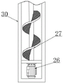
FIG. 3 is a schematic structural diagram of a discharging mechanism provided in an embodiment of the present invention;
fig. 4 is a schematic structural diagram of a limiting plate according to an embodiment of the present invention;
fig. 5 is a schematic diagram of the filter outer cylinder and the filter inner cylinder provided in the embodiment of the present invention.
In the drawings: 1. a frame; 2. a connecting flange; 3. a tapered tube; 4. a filtering outer cylinder; 5. a water pump; 6. a return pipe; 7. an electrically controlled valve; 8. a discharge pipe; 9. a water inlet; 10. filtering the inner cylinder; 11. a first auger; 12. a first motor; 13. a second auger; 14. mounting a plate; 15. a first through hole; 16. a one-way valve; 17. fixing a cutter; 18. a filter screen; 19. a second motor; 20. a square bar; 21. a worm; 22. a worm gear; 23. a rotating shaft; 24. a discharge plate; 25. a limiting plate; 26. a third motor; 27. a third packing auger; 28. a first notch; 29. a second notch; 30. a lifting cylinder; 31. an overflow valve; 100. a filtering mechanism; 101. a fluid filtering structure; 102. a solid-liquid separation structure; 200. a discharge mechanism.
Detailed Description
In order to make the objects, technical solutions and advantages of the present invention more apparent, the present invention is described in further detail below with reference to the accompanying drawings and embodiments. It should be understood that the specific embodiments described herein are merely illustrative of the invention and do not limit the invention.
Specific implementations of the present invention are described in detail below with reference to specific embodiments.
As shown in fig. 1, a schematic structural diagram of a high-efficiency filtering apparatus for water treatment according to an embodiment of the present invention is provided, where the high-efficiency filtering apparatus for water treatment includes:
the device comprises a rack 1, wherein a group of conical pipes 3 are fixedly arranged in the rack 1, and connecting flanges 2 are fixedly arranged at two ends of the rack 1;
the filtering mechanism 100 is embedded in the conical tube 3, is communicated with the conical tube 3, and is used for filtering the fluid entering the conical tube 3;
and the discharging mechanism 200 is fixedly arranged on the frame 1 and is used for filtering and discharging impurities from the filtering mechanism 100.
In this embodiment, during the use, with the pipeline cover of unidimensional on conical duct 3, utilize flange and flange 2 on the pipeline to press the pipeline to conical duct 3, and then the fluid in the pipeline enters into filtering mechanism 100 gradually, utilizes filtering mechanism 100 to filter it, filters the solid matter among them and separates, and then utilizes the solid matter discharge conical duct 3 that discharge mechanism 200 will collect to guarantee that filtering mechanism 100 can long-term effective operation.
As shown in fig. 1, as a preferred embodiment of the present invention, the filter mechanism 100 includes:
the fluid filtering structure 101, the fluid filtering structure 101 is fixedly installed on the conical pipe 3 and is used for filtering the entering fluid;
and the solid-liquid separation structures 102 are installed at two ends of the fluid filtering structure 101, and are used for collecting solid impurities from the fluid filtering structure 101 and conveying the solid impurities to the discharging mechanism 200.
In this embodiment, the present invention is suitable for the pressureless fluid, when in use, the fluid in the conical tube 3 enters the fluid filtering structure 101, and the fluid filtering structure 101 operates once at intervals, during which the solid matters carried by the pressureless fluid in the conical tube 3 will slowly accumulate in the fluid filtering structure 101, and finally, concentrated filtration is performed, and the solid-liquid separation structure 102 collects the solid matters, and conveys the solid matters to the discharging mechanism 200.
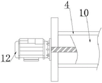
As shown in fig. 1, as a preferred embodiment of the present invention, the fluid filtering structure 101 includes an outer filtering cylinder 4 and an inner filtering cylinder 10, the outer filtering cylinder 4 is embedded in the tapered tube 3, one side of the outer filtering cylinder 4 is provided with a water inlet 9, and the other side is provided with a plurality of first through holes 15, the inner filtering cylinder 10 is slidably disposed in the outer filtering cylinder 4, one side of the inner filtering cylinder 10 is provided with an opening, and the other side is provided with a plurality of sets of filtering nets 18, the inner filtering cylinder 10 is internally and fixedly provided with a mounting plate 14, the mounting plate 14 is rotatably connected with a first auger 11 and a second auger 13, the first auger 11 is fixedly connected with the second auger 13, and the blades are opposite in rotation direction, the ends of the first auger 11 and the second auger 13, which are far away from each other, are both provided with square holes with rectangular cross sections, the outer filtering cylinder 4 is fixedly provided with a first motor 12, the first motor 12 is connected with the inner filtering cylinder 10 through a screw rod in a matching manner, the inner filtering cylinder 10 is rectangular in cross section, and the inner filtering cylinder 10 is provided with a one-way valve 16.
As shown in fig. 1, fig. 2 and fig. 4, as a preferred embodiment of the present invention, two sets of solid-liquid separation structures 102 are provided, and are respectively installed at two ends of the filtering outer cylinder 4, each solid-liquid separation structure 102 includes a second motor 19, a worm 21 is installed on the second motor 19, a square rod 20 is fixedly connected to an end of the worm 21, a limiting plate 25 is provided in the filtering outer cylinder 4, a set of rotating shaft 23 is rotatably installed on the filtering outer cylinder 4, a worm wheel 22 is installed on the rotating shaft 23, the worm wheel 22 is engaged with the worm 21, a plurality of sets of discharging plates 24 are installed on an outer diameter of the rotating shaft 23, a cutting edge is provided at one side of the discharging plates 24, and the limiting plate 25 is provided with a plurality of sets of first notches 28 and second notches 29.
In this embodiment, during filtering, fluid enters the inner filtering cylinder 10 through the water inlet 9 and the openings, and leaves after passing through the filtering screen 18, while solid matter is intercepted by the filtering screen 18, there are two sets of openings on the inner filtering cylinder 10, only one set of opening at a time is communicated with the water inlet 9, during operation, the inner filtering cylinder 10 is driven by the first motor 12 through the lead screw to slide to one end of the outer filtering cylinder 4, as exemplified by the inner filtering cylinder 10 sliding to the lower end of the outer filtering cylinder 4, at this time, the opening above the mounting plate 14 is communicated with the water inlet 9, fluid passes through the filtering screen 18 above the opening above the mounting plate 14, and then flows away through the first through hole 15 corresponding to the filtering screen 18, while the opening below the mounting plate 14 is not communicated with the water inlet 9, the portion below the mounting plate 14 is in a closed state, at this time, fluid passes through the filtering screen 18 above the mounting plate 14 continuously, accumulates at this time, while a large amount of solid matter has been collected in the portion below the mounting plate 14, and, when the inner filtering cylinder 10 slides to the lower end of the outer filtering cylinder 4, the inner filtering cylinder 10, the second filtering cylinder is connected with the second square rod 20, the second filtering pipe 11, the second rod drives the second filtering pipe 11 to drive the inner filtering screen 18 through the first motor, the one-way, the second filtering pipe 24, the second filtering cylinder 11, the one-way, the second filtering cylinder 11, the second motor 16, the one-way of the second filtering cylinder 16, the screw 21 is provided with the first through the one-way, the one-way screw valve, the one-way screw 21, the cutting edge is matched with the fixed cutter 17 to further shred the solid substances, then the discharge plate 24 returns to the position above the limit plate 25 through the first notch 28, the width of the first notch 28 is the same as that of the discharge plate 24, so that the shredded solid substances are prevented from returning to the position above the limit plate 25, and under the driving of the discharge mechanism 200, the fluid drives the shredded solid substances to enter the discharge mechanism 200 and finally to be discharged through the discharge mechanism 200; after a certain period of operation, the first motor 12 is reversed to complete the cleaning of the solid matter at the other end of the outer cylinder 4, and the stationary cutter 17 is positioned to cut up the solid matter for convenient discharge into the discharge mechanism 200.
As shown in fig. 1 and fig. 3, as a preferred embodiment of the present invention, the discharging mechanism 200 includes a water pump 5 and a lifting cylinder 30, the water pump 5 is connected to an outlet pipe 8 through an electric control valve 7, the water pump 5 is further communicated with a conical pipe 3, the outlet pipe 8 is communicated with two ends of the filtering outer cylinder 4, the lifting cylinder 30 is fixedly mounted on the frame 1, a third packing auger 27 is mounted in the lifting cylinder 30, blades of the third packing auger 27 are of a net structure, the lifting cylinder 30 is communicated with two ends of the filtering outer cylinder 4 through a return pipe 6, and the lifting cylinder 30 is communicated with the conical pipe 3 through an overflow valve 31.
In this embodiment, the third auger 27 is driven by the third motor 26, when the chopped solid matter is located below the limit plate 25, the fluid passing through the filter screen 18 is extracted by the water pump 5 and is conveyed to the position below the limit plate 25 through the outlet pipe 8, the fluid below the limit plate 25 enters the lifting cylinder 30 along with the return pipe 6, and the solid matter will gradually rise along the lifting cylinder 30 until being discharged under the driving of the third auger 27.
As a preferred embodiment of the invention, the frame 1 is provided with a collection tank for collecting the discharged solid impurities.
As a preferred embodiment of the present invention, the inner wall of the tapered tube 3 is coated with a corrosion-resistant layer.
The above description is only for the purpose of illustrating the preferred embodiments of the present invention and is not to be construed as limiting the invention, and any modifications, equivalents and improvements made within the spirit and principle of the present invention are intended to be included within the scope of the present invention.
Claims (4)
1. A high efficiency filter apparatus for water treatment, comprising:
the device comprises a rack, a group of conical pipes are fixedly arranged in the rack, and connecting flanges are fixedly arranged at two ends of the rack;
the filtering mechanism is embedded in the conical pipe, is communicated with the conical pipe and is used for filtering the fluid entering the conical pipe;
the discharging mechanism is fixedly arranged on the rack and is used for filtering and discharging impurities from the filtering mechanism;
the filter mechanism includes:
the fluid filtering structure is fixedly arranged on the conical tube and is used for filtering the entering fluid;
the solid-liquid separation structures are arranged at two ends of the fluid filtering structure and used for collecting solid impurities from the fluid filtering structure and conveying the solid impurities to the discharging mechanism;
the fluid filtering structure comprises an outer filtering barrel and an inner filtering barrel, the outer filtering barrel is embedded and installed on the tapered pipe, one side of the outer filtering barrel is provided with a water inlet, the other side of the outer filtering barrel is provided with a plurality of first through holes, the inner filtering barrel is arranged in the outer filtering barrel in a sliding mode, one side of the inner filtering barrel is provided with an opening, the other side of the inner filtering barrel is provided with a plurality of groups of filter screens, an installation plate is fixedly arranged in the inner filtering barrel, the installation plate is rotatably connected with a first auger and a second auger, the first auger and the second auger are fixedly connected, the rotating directions of blades are opposite, one ends, far away from each other, of the first auger and the second auger are provided with square holes with rectangular cross sections, a first motor is fixedly installed on the outer filtering barrel and is matched and connected with the inner filtering barrel through a lead screw, the cross section of the inner filtering barrel is rectangular, and a one-way valve is arranged on the inner filtering barrel;
the solid-liquid separation structure comprises two groups of solid-liquid separation structures which are respectively arranged at two ends of the filtering outer cylinder body, each solid-liquid separation structure comprises a second motor, a worm is arranged on each second motor, a square rod is fixedly connected to the end part of each worm, a limiting plate is arranged in the filtering outer cylinder body, a group of rotating shafts are rotatably arranged on the filtering outer cylinder body, worm wheels are arranged on the rotating shafts and meshed with the worms, a plurality of groups of discharging plates are arranged on the outer diameters of the rotating shafts, a cutting edge is arranged on one side of each discharging plate, and a plurality of groups of first notches and second notches are formed in the limiting plates;
the openings in the filtering inner cylinder body are arranged in two groups and are respectively located above and below the mounting plate, when the filter is in work, the motor drives the filtering inner cylinder body to slide to one end of the filtering outer cylinder body through the lead screw, only one group of openings is communicated with the water inlet at each time, and the first packing auger and the second packing auger are connected with the square rod through square holes.
2. The efficient filtering equipment for water treatment as claimed in claim 1, wherein the discharging mechanism comprises a water pump and a lifting cylinder, the water pump is connected with a flow outlet pipe through an electric control valve, the water pump is further communicated with a conical pipe, the flow outlet pipe is communicated with two ends of the filtering outer cylinder, the lifting cylinder is fixedly mounted on the frame, a third packing auger is mounted in the lifting cylinder, blades of the third packing auger are of a net structure, the lifting cylinder is communicated with two ends of the filtering outer cylinder through a return pipe, and the lifting cylinder is communicated with the conical pipe through an overflow valve.
3. A high efficiency filter apparatus for water treatment as claimed in claim 1, wherein a collection tank is provided on the frame for collecting discharged solid impurities.
4. A high efficiency filter device for water treatment as claimed in claim 1, wherein the inner wall of the conical tube is coated with a corrosion resistant layer.
Priority Applications (1)
| Application Number | Priority Date | Filing Date | Title |
|---|---|---|---|
| CN202210806980.9A CN114849315B (en) | 2022-07-11 | 2022-07-11 | High-efficient filtration equipment for water treatment |
Applications Claiming Priority (1)
| Application Number | Priority Date | Filing Date | Title |
|---|---|---|---|
| CN202210806980.9A CN114849315B (en) | 2022-07-11 | 2022-07-11 | High-efficient filtration equipment for water treatment |
Publications (2)
| Publication Number | Publication Date |
|---|---|
| CN114849315A CN114849315A (en) | 2022-08-05 |
| CN114849315B true CN114849315B (en) | 2022-11-29 |
Family
ID=82626468
Family Applications (1)
| Application Number | Title | Priority Date | Filing Date |
|---|---|---|---|
| CN202210806980.9A Active CN114849315B (en) | 2022-07-11 | 2022-07-11 | High-efficient filtration equipment for water treatment |
Country Status (1)
| Country | Link |
|---|---|
| CN (1) | CN114849315B (en) |
Family Cites Families (5)
| Publication number | Priority date | Publication date | Assignee | Title |
|---|---|---|---|---|
| CN215742138U (en) * | 2021-06-30 | 2022-02-08 | 青岛致通化学有限公司 | Conveying device for purifying water |
| CN216092640U (en) * | 2021-11-04 | 2022-03-22 | 湖南志成环境工程有限公司 | Efficient and energy-saving sewage treatment integrated equipment |
| CN216798956U (en) * | 2021-12-08 | 2022-06-24 | 山西智创药研科技有限公司 | Filtration production facility is used to medicine intermediate preparation |
| CN216358155U (en) * | 2021-12-27 | 2022-04-22 | 云南元江大有为食品有限公司 | A liquid manure integration root system drips irrigation device for mango is planted |
| CN216825036U (en) * | 2022-02-22 | 2022-06-28 | 武汉荣众通机电科技有限公司 | Water-slag separating device of numerical control machine tool |
-
2022
- 2022-07-11 CN CN202210806980.9A patent/CN114849315B/en active Active
Also Published As
| Publication number | Publication date |
|---|---|
| CN114849315A (en) | 2022-08-05 |
Similar Documents
| Publication | Publication Date | Title |
|---|---|---|
| CN114849315B (en) | High-efficient filtration equipment for water treatment | |
| CN213803186U (en) | High-efficient sewage stage filter equipment | |
| CN210559728U (en) | Solid-liquid separation device for industrial sewage treatment | |
| CN112320985A (en) | Intelligent centralized treatment system for sewage station | |
| CN116966661A (en) | Environment-friendly filter equipment for hydraulic engineering | |
| CN116536088A (en) | Natural gas rapid filtering and purifying box and method | |
| CN213652049U (en) | Harmful substance recovery unit for water purifier | |
| CN215742068U (en) | Heavy metal wastewater filters with filter equipment who is difficult for blockking up | |
| CN211445452U (en) | Sewage treatment tank capable of automatically cleaning sludge at tank bottom | |
| CN213253218U (en) | Waste water shunting device | |
| CN219462690U (en) | Sewage sludge treatment device for urban river | |
| CN210845416U (en) | Integrated equipment for eutrophic water treatment | |
| CN113304540A (en) | Domestic waste sewage purification device | |
| CN220485465U (en) | Anti-blocking microbial degradation sewage treatment device | |
| CN220990208U (en) | Comprehensive treatment device for waste gas | |
| CN218458764U (en) | Water treatment filter disc and filter | |
| CN115571935B (en) | Building water supply and drainage system | |
| CN220182934U (en) | High-salt high-organic wastewater treatment and separation equipment | |
| CN220939428U (en) | Sewage impurity removing device | |
| CN114344991B (en) | Suspended matter discharge equipment for purifying black and odorous water body of sewer | |
| CN215609835U (en) | Microfiltration solid-liquid separator | |
| CN220513553U (en) | Water impurity separation filter equipment | |
| CN211367313U (en) | Novel MBR membrane sewage treatment device | |
| CN219744256U (en) | Atmospheric pollution treatment equipment | |
| CN220098693U (en) | High-efficient preprocessing device of methyl chloroacetate waste water |
Legal Events
| Date | Code | Title | Description |
|---|---|---|---|
| PB01 | Publication | ||
| PB01 | Publication | ||
| SE01 | Entry into force of request for substantive examination | ||
| SE01 | Entry into force of request for substantive examination | ||
| GR01 | Patent grant | ||
| GR01 | Patent grant |