CN114779055A - Automatic check out test set of electrical control board - Google Patents
Automatic check out test set of electrical control board Download PDFInfo
- Publication number
- CN114779055A CN114779055A CN202210696579.4A CN202210696579A CN114779055A CN 114779055 A CN114779055 A CN 114779055A CN 202210696579 A CN202210696579 A CN 202210696579A CN 114779055 A CN114779055 A CN 114779055A
- Authority
- CN
- China
- Prior art keywords
- mounting
- control board
- screw rod
- electric control
- control
- Prior art date
- Legal status (The legal status is an assumption and is not a legal conclusion. Google has not performed a legal analysis and makes no representation as to the accuracy of the status listed.)
- Pending
Links
- 238000012360 testing method Methods 0.000 title claims description 6
- 238000001514 detection method Methods 0.000 claims abstract description 87
- 239000002184 metal Substances 0.000 claims abstract description 26
- 230000007246 mechanism Effects 0.000 claims abstract description 25
- 230000005540 biological transmission Effects 0.000 claims description 27
- 244000309464 bull Species 0.000 claims description 8
- 230000000694 effects Effects 0.000 claims description 6
- 238000009434 installation Methods 0.000 claims 4
- 230000009471 action Effects 0.000 abstract description 8
- 230000008859 change Effects 0.000 abstract description 5
- 238000007689 inspection Methods 0.000 description 9
- 238000010586 diagram Methods 0.000 description 4
- 238000000034 method Methods 0.000 description 4
- 230000008569 process Effects 0.000 description 3
- 230000009286 beneficial effect Effects 0.000 description 2
- 230000004888 barrier function Effects 0.000 description 1
- 230000006835 compression Effects 0.000 description 1
- 238000007906 compression Methods 0.000 description 1
- 230000007547 defect Effects 0.000 description 1
- 230000002349 favourable effect Effects 0.000 description 1
- 238000004519 manufacturing process Methods 0.000 description 1
- 238000012986 modification Methods 0.000 description 1
- 230000004048 modification Effects 0.000 description 1
- 230000001737 promoting effect Effects 0.000 description 1
- 230000001105 regulatory effect Effects 0.000 description 1
- 238000011895 specific detection Methods 0.000 description 1
- 238000003466 welding Methods 0.000 description 1
Images


Classifications
-
- G—PHYSICS
- G01—MEASURING; TESTING
- G01R—MEASURING ELECTRIC VARIABLES; MEASURING MAGNETIC VARIABLES
- G01R31/00—Arrangements for testing electric properties; Arrangements for locating electric faults; Arrangements for electrical testing characterised by what is being tested not provided for elsewhere
- G01R31/28—Testing of electronic circuits, e.g. by signal tracer
- G01R31/2801—Testing of printed circuits, backplanes, motherboards, hybrid circuits or carriers for multichip packages [MCP]
- G01R31/2806—Apparatus therefor, e.g. test stations, drivers, analysers, conveyors
- G01R31/2808—Holding, conveying or contacting devices, e.g. test adapters, edge connectors, extender boards
-
- B—PERFORMING OPERATIONS; TRANSPORTING
- B25—HAND TOOLS; PORTABLE POWER-DRIVEN TOOLS; MANIPULATORS
- B25H—WORKSHOP EQUIPMENT, e.g. FOR MARKING-OUT WORK; STORAGE MEANS FOR WORKSHOPS
- B25H1/00—Work benches; Portable stands or supports for positioning portable tools or work to be operated on thereby
- B25H1/08—Work benches; Portable stands or supports for positioning portable tools or work to be operated on thereby with provision for attachment of work holders
-
- G—PHYSICS
- G01—MEASURING; TESTING
- G01R—MEASURING ELECTRIC VARIABLES; MEASURING MAGNETIC VARIABLES
- G01R1/00—Details of instruments or arrangements of the types included in groups G01R5/00 - G01R13/00 and G01R31/00
- G01R1/02—General constructional details
- G01R1/04—Housings; Supporting members; Arrangements of terminals
- G01R1/0408—Test fixtures or contact fields; Connectors or connecting adaptors; Test clips; Test sockets
- G01R1/0416—Connectors, terminals
-
- G—PHYSICS
- G01—MEASURING; TESTING
- G01R—MEASURING ELECTRIC VARIABLES; MEASURING MAGNETIC VARIABLES
- G01R31/00—Arrangements for testing electric properties; Arrangements for locating electric faults; Arrangements for electrical testing characterised by what is being tested not provided for elsewhere
- G01R31/28—Testing of electronic circuits, e.g. by signal tracer
- G01R31/2801—Testing of printed circuits, backplanes, motherboards, hybrid circuits or carriers for multichip packages [MCP]
- G01R31/2806—Apparatus therefor, e.g. test stations, drivers, analysers, conveyors
-
- H—ELECTRICITY
- H01—ELECTRIC ELEMENTS
- H01R—ELECTRICALLY-CONDUCTIVE CONNECTIONS; STRUCTURAL ASSOCIATIONS OF A PLURALITY OF MUTUALLY-INSULATED ELECTRICAL CONNECTING ELEMENTS; COUPLING DEVICES; CURRENT COLLECTORS
- H01R13/00—Details of coupling devices of the kinds covered by groups H01R12/70 or H01R24/00 - H01R33/00
- H01R13/02—Contact members
Abstract
The invention provides automatic detection equipment for an electric control panel, which relates to the technical field of electric control panel detection and comprises a workbench, wherein mounting plates are fixedly mounted on two sides of the upper surface of the workbench, a placing table is movably mounted between the two mounting plates, a workpiece positioning mechanism for fixing a workpiece is arranged on the upper surface of the placing table, and a driving mechanism for driving the placing table to move is arranged on one side of the workbench. According to the invention, through the wavy design of the annular metal connecting sheet, under the connecting action of the auxiliary spring, the annular metal connecting sheet can be changed according to the shape of the spherical contact on the surface of the circuit board, so that the annular conductive block and the annular metal connecting sheet have larger contact areas with the contact on the circuit board, the occurrence of broken contact can be effectively reduced, the detection work is more facilitated, and the detection contact can be suitable for detection contacts with different sizes on electric control boards of different models due to the change of the overall shape of the annular metal connecting sheet.
Description
Technical Field
The invention relates to the technical field of detection of electrical control boards, in particular to automatic detection equipment for the electrical control boards.
Background
The electrical control board is the most basic component equipment in the electrical control system, and is also an important component for ensuring the normal operation of the whole electrical control system, so the quality requirement of the electrical control board is extremely high, the electrical control board needs to be detected after production and processing are finished, so the electrical control board can be ensured to be normally used, a specific detection device is generally adopted to detect the electrical control board, but the existing detection device generally places the electrical control board in the detection device manually for detection when in use, so the test efficiency is lower, moreover, the position of a detection contact of the existing detection device is generally fixedly arranged, the position cannot be adjusted according to the model of the electrical control board to be detected, and the input and output terminals on the surface of the common electrical control board are hemispherical convex contacts formed by spot welding, when the detection contact of check out test set contacted with the hemispherical contact on electrical control board surface, because the contact is spherical protruding shape, can make detection contact less rather than area of contact, at the testing process, the condition of breaking contact appears easily, and then influences electrical control board's detection efficiency, therefore we improve this, provide an electrical control board automation check out test set.
Disclosure of Invention
Aiming at the defects of the prior art, the invention provides automatic detection equipment for an electrical control board, which solves the problems that the detection efficiency is low due to manual detection, the position of a detection contact can not be adjusted according to different models of the electrical control board, and the detection process is influenced due to the small contact area between the detection contact and the electrical control board caused by the shape of a contact.
In order to realize the purpose, the invention adopts the technical scheme that:
the automatic detection equipment for the electric control panel comprises a workbench, wherein mounting plates are fixedly mounted on two sides of the upper surface of the workbench, a placing table is movably mounted between the two mounting plates, a workpiece positioning mechanism used for fixing a workpiece is arranged on the upper surface of the placing table, and a driving mechanism used for driving the placing table to move is arranged on one side of the workbench;
every equal fixed mounting in upper surface middle part of mounting panel has the bracing piece, two the activity is provided with the diaphragm between the bracing piece, the bottom of diaphragm is provided with carries out the detection contact that detects to the work piece, the inside of diaphragm still is provided with carries out the position control mechanism that the position moved to the detection contact.
As preferred, every a side surface of mounting panel has all seted up first mounting groove, actuating mechanism is including the mounting bracket, mounting bracket fixed mounting is in lower surface one side of workstation, one side fixed mounting of mounting bracket has second servo motor, the worm is installed to second servo motor's output, the other end of worm rotates the inside one side that sets up at the mounting bracket, the bottom of mounting bracket is rotated and is installed the bull stick, fixed mounting has the worm wheel on the pole body of bull stick, intermeshing between worm wheel and the worm.
As preferred, the top of bull stick runs through workstation and tip and rotates the one side that sets up at one of them mounting panel, the bull stick is located the pole body of workstation top and is fixed mounting has drive gear, the meshing of one side of drive gear has driving toothed plate, driving toothed plate slides and sets up inside the first mounting groove of corresponding position, the inside of first mounting groove still is provided with and is used for carrying out slidable mounting at supplementary spout to driving toothed plate, one side fixed mounting that places the platform is on one side surface of driving toothed plate, the opposite side that places the platform slides and sets up the inside of keeping away from the first mounting groove of driving toothed plate one side.
Preferably, every a third mounting groove has all been seted up to a side surface of bracing piece, one of them last fixed surface of bracing piece installs driving motor, second accommodate the lead screw is installed to driving motor's output, the other end of second accommodate the lead screw rotates and sets up on the bottom inner wall of the third mounting groove of corresponding position, the activity is provided with the second lead screw cover on the pole body of second accommodate the lead screw, one side fixed mounting of second lead screw cover is on a side surface of diaphragm, the opposite side of diaphragm slides and sets up the inside at the third mounting groove of corresponding position.
Preferably, the workpiece positioning mechanism includes a first workpiece baffle, a second workpiece baffle and a second mounting groove, the first workpiece baffle and the second workpiece baffle are respectively and fixedly mounted on one side of the upper surface of the placing table, the second mounting grooves are respectively and fixedly mounted on the upper surface of the placing table, and a first servo motor is fixedly mounted on one side of the outer surface of the placing table and located in each second mounting groove.
Preferably, the output end of each first servo motor is provided with a first adjusting screw rod, the other end of each first adjusting screw rod is rotatably arranged on the inner wall of one end of the corresponding second mounting groove, and a first screw rod sleeve is movably arranged on the rod body of each first adjusting screw rod.
Preferably, a first auxiliary push plate is fixedly mounted at the top of one of the first screw rod sleeves, a second auxiliary push plate is fixedly mounted at the top of the other one of the first screw rod sleeves, the first auxiliary push plate corresponds to the first workpiece baffle, and the second auxiliary push plate corresponds to the second workpiece baffle.
As preferred, first adjustment tank has all been seted up, every to the lower surface both sides of diaphragm the second adjustment tank has all been seted up on the bottom inner wall of first adjustment tank, position control mechanism is including first control motor, first control motor fixed mounting just is located one side of every second adjustment tank at a side surface of diaphragm, every first control lead screw, every are all installed to first control motor's output the other end of first control lead screw all rotates the setting on the one end inner wall of the second adjustment tank of corresponding position, every equal movable mounting has first control lead screw cover on the pole body of first control lead screw.
Preferably, every the bottom of first control lead screw cover is all fixed mounting has the movable plate, every one side of movable plate all slides and sets up on the inner wall of one side of first adjustment tank, every the third adjustment tank has all been seted up to the lower surface of movable plate, every second control motor is all installed on the one end surface of movable plate, every second control lead screw is all installed to the output of second control motor, every the other end of second control lead screw all rotates and sets up on the bottom inner wall of the third adjustment tank of corresponding position, every equal movable mounting has the second control lead screw cover on the pole body of second control lead screw.
Preferably, the detection contact comprises an extension rod, the extension rod is fixedly installed on the lower surface of each second control lead screw sleeve, an annular connecting plate is arranged on the outer side of the lower surface of each extension rod, an auxiliary spring is further installed on the lower surface of each extension rod, an annular auxiliary plate is installed at the bottom of each auxiliary spring, an annular conductive block is installed on the lower surface of each annular auxiliary plate, an annular metal connecting piece is arranged between the outer surface of each annular conductive block and the inner surface of each annular connecting plate, the bottom of each annular conductive block is in a concave shape, and the annular metal connecting pieces are in a wavy shape.
Compared with the prior art, the invention has the following beneficial effects:
1. the positions of two detection contacts at different positions can be respectively adjusted, the positions of input and output ports on the surface of the electric control panel can be different due to the different models of the electric control panel, the positions of the detection contacts can be respectively adjusted according to the different models of the electric control panel, so that the detection equipment can be suitable for the electric control panels of different models, the detection cost can be effectively reduced, because the annular metal connecting sheet is arranged in a wavy compression manner, under the connecting action of an auxiliary spring, the whole position of the extension rod moves downwards under the abutting action of the spherical contact on the surface of the circuit board below, the annular conductive block can move upwards to drive the annular metal connecting sheet on the outer side of the annular metal connecting sheet to move, the annular metal connecting sheet can be changed according to the shape of the spherical contact on the surface of the circuit board, and the annular conductive block and the annular metal connecting sheet can have larger contact areas with the contacts on the circuit board through the concave arrangement of the lower surface of the annular conductive block, the occurrence of the broken contact condition can be effectively reduced, the detection work is more facilitated, and the change of the overall shape of the annular metal connecting sheet enables the detection contact to be suitable for detection contacts of different sizes on electric control boards of different models.
2. The position through first supplementary push pedal and the supplementary push pedal of second removes under the effect of first work piece baffle and second work piece baffle, can fix the position of electrical control board, because the position of first work piece baffle and second work piece baffle is fixed the setting, fix in the same position department of placing platform surface when fixing the electrical control board of the same model each time, it detects the work to make things convenient for more, through the meshing transmission between worm wheel and worm and drive gear and the driving toothed plate, under second servo motor's drive, can realize the automatic transport and the detection work to electrical control board, can effectively improve detection efficiency, the position that places the platform removes the precision and also obtains effectively promoting, position control to placing the platform is more accurate, it is also more stable at the removal in-process.
Drawings
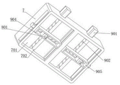
FIG. 1 is a schematic diagram of the overall structure of an automatic inspection apparatus for electrical control boards according to the present invention;
FIG. 2 is a side view of an automated inspection apparatus for electrical control panels according to the present invention;
FIG. 3 is a schematic cross-sectional view taken along line A-A of FIG. 2 illustrating an automated inspection apparatus for electrical control boards according to the present invention;
FIG. 4 is a schematic diagram of the internal structure of the mounting rack of the automatic inspection equipment for electrical control boards according to the present invention;
FIG. 5 is an overall side internal cross-sectional view of an automated inspection apparatus for electrical control panels according to the present invention;
FIG. 6 is a schematic cross-sectional view taken along line B-B in FIG. 2 of an automatic inspection apparatus for electrical control boards according to the present invention;
FIG. 7 is an enlarged view of the inspection apparatus for automatically inspecting an electrical control board of the present invention at C of FIG. 6;
fig. 8 is a schematic structural diagram of a placing table of an automatic detection device for an electrical control board according to the present invention;
FIG. 9 is a schematic diagram of a detailed structure of the bottom of the transverse plate of the automatic detection equipment for electrical control panels according to the present invention;
FIG. 10 is a side view of the cross plate of the automatic inspection apparatus for electrical control panels of the present invention;
FIG. 11 is a schematic cross-sectional view taken along line D-D in FIG. 10 of an automated inspection apparatus for electrical control boards according to the present invention;
FIG. 12 is a schematic view of a specific structure of a detection contact of the automatic detection equipment for an electrical control board according to the present invention;
fig. 13 is a cross-sectional view of the internal structure of the detection contact of the automatic detection equipment of the electric control board of the invention.
In the figure: 1. a work table; 2. mounting a plate; 201. a first mounting groove; 2011. an auxiliary chute; 3. a placing table; 4. a workpiece positioning mechanism; 401. a first workpiece barrier; 402. a second workpiece baffle; 403. a second mounting groove; 404. a first servo motor; 405. a first adjusting screw rod; 406. a first screw rod sleeve; 407. a first auxiliary push plate; 408. a second auxiliary push plate; 5. a drive mechanism; 501. a mounting frame; 502. a second servo motor; 503. a worm; 504. a worm gear; 505. a rotating rod; 506. a transmission gear; 507. a transmission toothed plate; 6. a support bar; 601. a drive motor; 602. a third mounting groove; 603. a second adjusting screw rod; 604. a second screw rod sleeve; 7. a transverse plate; 701. a first regulating groove; 702. a second adjustment groove; 8. detecting a contact; 801. an extension rod; 802. an annular connecting plate; 803. an auxiliary spring; 804. an annular auxiliary plate; 805. an annular conductive block; 806. an annular metal connecting sheet; 9. a position adjustment mechanism; 901. a first control motor; 902. a first control screw rod; 903. a first control lead screw sleeve; 904. moving the plate; 905. a third adjustment tank; 906. a second control motor; 907. a second control screw rod; 908. and the second control lead screw sleeve.
Detailed Description
The technical solutions in the embodiments of the present invention will be clearly and completely described below with reference to the embodiments of the present invention, and it is obvious that the described embodiments are only a part of the embodiments of the present invention, and not all of the embodiments. All other embodiments, which can be derived by a person skilled in the art from the embodiments given herein without making any creative effort, shall fall within the protection scope of the present invention.
As shown in fig. 1 and 2, an automatic detection device for an electrical control panel comprises a workbench 1, wherein mounting plates 2 are fixedly mounted on both sides of the upper surface of the workbench 1, a placing table 3 is movably mounted between the two mounting plates 2, a workpiece positioning mechanism 4 for fixing a workpiece is arranged on the upper surface of the placing table 3, and a driving mechanism 5 for driving the placing table 3 to move is arranged on one side of the workbench 1;
the middle part of the upper surface of each mounting plate 2 is fixedly provided with a support rod 6, a transverse plate 7 is movably arranged between the two support rods 6, the bottom of the transverse plate 7 is provided with a detection contact 8 for detecting a workpiece, and the inside of the transverse plate 7 is also provided with a position adjusting mechanism 9 for moving the detection contact 8.
As shown in fig. 2, 3 and 4, a first mounting groove 201 is formed in a surface of one side of each mounting plate 2, the driving mechanism 5 includes a mounting frame 501, the mounting frame 501 is fixedly mounted on one side of a lower surface of the workbench 1, a second servo motor 502 is fixedly mounted on one side of the mounting frame 501, a worm 503 is mounted at an output end of the second servo motor 502, the other end of the worm 503 is rotatably disposed on one side of the inside of the mounting frame 501, a rotating rod 505 is rotatably mounted at a bottom of the mounting frame 501, a worm wheel 504 is fixedly mounted on a rod body of the rotating rod 505, the worm wheel 504 and the worm 503 are engaged with each other, a top of the rotating rod 505 penetrates through the workbench 1, an end portion of the rotating rod is rotatably disposed on one side of one of the mounting plates 2, a transmission gear 506 is fixedly mounted on a rod body of the rotating rod 505 above the workbench 1, one side of the transmission gear 506 is engaged with a transmission toothed plate 507, the transmission toothed plate 507 is slidably disposed inside the first mounting groove 201 at a corresponding position, the inside of first mounting groove 201 still is provided with and is used for carrying out slidable mounting at supplementary spout 2011 to transmission toothed plate 507, one side fixed mounting who places platform 3 is on one side surface of transmission toothed plate 507, the opposite side that places platform 3 slides and sets up in the inside of keeping away from the first mounting groove 201 of transmission toothed plate 507 one side, the drive through actuating mechanism 5 can change the position of placing platform 3, thereby accomplish the automatic transport work to electrical control board, can effectively improve detection efficiency, the meshing transmission between worm wheel 504 and the worm 503 can make the position control who places platform 3 more accurate, more conveniently detect work.
As shown in fig. 5, 6, and 7, a third mounting groove 602 is formed in a side surface of each support bar 6, a driving motor 601 is fixedly mounted on an upper surface of one of the support bars 6, a second adjusting screw 603 is mounted at an output end of the driving motor 601, another end of the second adjusting screw 603 is rotatably disposed on an inner wall of a bottom of the third mounting groove 602 at a corresponding position, a second screw sleeve 604 is movably disposed on a shaft of the second adjusting screw 603, one side of the second screw sleeve 604 is fixedly mounted on a side surface of the transverse plate 7, and another side of the transverse plate 7 is slidably disposed inside the third mounting groove 602 at a corresponding position.
As shown in fig. 8, the workpiece positioning mechanism 4 includes a first workpiece baffle 401, a second workpiece baffle 402 and a second mounting groove 403, the first workpiece baffle 401 and the second workpiece baffle 402 are respectively fixedly mounted on one side of the upper surface of the placing table 3, the second mounting groove 403 is respectively disposed on the upper surface of the placing table 3, a first servo motor 404 is fixedly mounted on the outer surface of the placing table 3 and on one side of each second mounting groove 403, a first adjusting screw 405 is mounted on the output end of each first servo motor 404, the other end of each first adjusting screw 405 is rotatably disposed on the inner wall of one end of the corresponding second mounting groove 403, a first screw sleeve 406 is movably mounted on the shaft of each first adjusting screw 405, a first auxiliary push plate 407 is fixedly mounted on the top of one of the first screw sleeves 406, a second auxiliary push plate 408 is fixedly mounted on the top of the other first screw sleeve 406, the position of first supplementary push pedal 407 and first work piece baffle 401 is corresponding, and the position of supplementary push pedal 408 of second and second work piece baffle 402 is corresponding, through the removal respectively of first supplementary push pedal 407 and supplementary push pedal 408 of second, can carry out spacing fixed to the position of electrical control board, all has better fixed effect to the electrical control board of different models, is favorable to going on of detection achievement more.
As shown in fig. 9, 10 and 11, two sides of the lower surface of the horizontal plate 7 are respectively provided with a first adjusting groove 701, a second adjusting groove 702 is respectively provided on the inner wall of the bottom of each first adjusting groove 701, the position adjusting mechanism 9 includes a first control motor 901, the first control motor 901 is fixedly installed on the surface of one side of the horizontal plate 7 and is located on one side of each second adjusting groove 702, the output end of each first control motor 901 is provided with a first control screw 902, the other end of each first control screw 902 is rotatably installed on the inner wall of one end of the corresponding second adjusting groove 702, the shaft of each first control screw 902 is movably installed with a first control screw sleeve 903, the bottom moving plate 903 of each first control screw sleeve is fixedly installed with a moving plate 904, one side of each first control screw sleeve 904 is slidably installed on the inner wall of one side of the first adjusting groove 701, the lower surface of each moving plate 904 is provided with a third adjusting groove 905, a second control motor 906 is installed on one end surface of each moving plate 904, a second control screw rod 907 is installed at the output end of each second control motor 906, the other end of each second control screw rod 907 is rotatably arranged on the inner wall of the bottom end of a third adjusting groove 905 at a corresponding position, a second control screw rod sleeve 908 is movably installed on the rod body of each second control screw rod 907, and the two first control motors 901 and the second control motor 906 can be respectively controlled, so that the positions of two detection contacts 8 at different positions can be respectively adjusted, and under the threaded fit among the first control screw rod 902, the second control screw rod 907, the first control screw rod sleeve 903 and the second control screw rod sleeve 908, the positions of the detection contacts 8 can be adjusted in multiple directions, and can be adjusted according to the specific model of the electric control plate, so that the use is more convenient.
As shown in fig. 12 and 13, the detecting contact 8 includes an extending rod 801, the extending rod 801 is fixedly installed on the lower surface of each second control screw rod sleeve 908, an annular connecting plate 802 is arranged on the outer side of the lower surface of each extending rod 801, an auxiliary spring 803 is further installed on the lower surface of each extending rod 801, an annular auxiliary plate 804 is installed at the bottom of the auxiliary spring 803, an annular conductive block 805 is installed on the lower surface of the annular auxiliary plate 804, an annular metal connecting plate 806 is arranged between the outer surface of the annular conductive block 805 and the inner surface of the annular connecting plate 802, the bottom of the annular conductive block 805 is concave, the annular metal connecting plate 806 is arranged in a wavy manner, the shape of the bottom of the detecting contact 8 can be changed through the connecting action of the annular metal connecting plate 806 and the auxiliary spring 803 arranged in a wavy manner, and a larger contact area is provided between the detecting contact and the spherical detecting contact on the surface of the electrical control board, and the detection work is more facilitated.
The working principle of the automatic detection equipment for the electric control board is as follows:
when the device is used, an electric control board to be detected is placed on the placing table 3, the position of the electric control board can be limited through the workpiece positioning mechanism 4, the two first servo motors 404 are started to enable the two first adjusting screw rods 405 to rotate, the first screw rod sleeves 406 can move under the screw thread matching action between the first adjusting screw rods 405 and the first screw rod sleeves 406, so as to drive the first auxiliary push plate 407 and the second auxiliary push plate 408 to move, the movement of the first auxiliary push plate 407 can push a workpiece on the surface of the placing table 3 to move to the position of the first workpiece baffle 401, the movement of the second auxiliary push plate 408 can push the workpiece to move to the position of the second workpiece baffle 402, so that two sides of the workpiece are respectively positioned between the first auxiliary push plate 407 and the first workpiece baffle 401 and between the second auxiliary push plate 408 and the second workpiece baffle 402, and because the positions of the first workpiece baffle 401 and the second workpiece baffle 402 are fixedly arranged, when the same type of electric control board is fixed each time, the electric control board is fixed at the same position on the surface of the placing table 3, detection work is more convenient, the worm 503 is rotated through the operation of the second servo motor 502, the worm wheel 504 can drive the rotating rod 505 to rotate under the meshing transmission between the worm 503 and the worm wheel 504, so that the transmission gear 506 rotates, then through the meshing transmission between the transmission gear 506 and the transmission toothed plate 507, the transmission gear 506 rotates to drive the transmission toothed plate 507 to move horizontally, so that the whole placing table 3 can slide between the two mounting plates 2 and stop when sliding to the lower part of the transverse plate 7, detection work is carried out, through the meshing transmission between the worm wheel 504 and the worm 503 and between the transmission gear 506 and the transmission toothed plate 507, under the driving of the second servo motor 502, automatic conveying and detection work of the electric control board can be realized, the detection efficiency can be effectively improved, the position moving precision of the placing table 3 is also effectively improved, the position control of the placing table 3 is more accurate, the movement process is more stable, when the detection work of the electric control panel is carried out, firstly, the second adjusting screw 603 is driven to rotate by the driving motor 601, under the meshing transmission between the second adjusting screw 603 and the second screw sleeve 604, the second screw sleeve 604 drives the whole transverse plate 7 to move downwards, so that the detection contact 8 at the bottom of the transverse plate 7 is contacted with the surface of the electric control panel, the two detection contacts 8 are respectively connected with the input port and the output port of the electric control panel to form a detection loop, the detection contact 8 is electrically connected with a detection host, the detection host can adjust the detection program according to the type of the electric control panel, display and record the detection data, thereby completing the detection work, when the detection contact 8 moves to the upper part of the electric control panel, through the driving of the first control motor 901 and the second control motor 906, under the screw-thread fit between the first control screw rod 902 and the second control screw rod 907 and between the first control screw rod sleeve 903 and the second control screw rod sleeve 908, the positions of the two detection contacts 8 at different positions can be respectively adjusted, the positions of the input port and the output port on the surface of the electric control board can be different due to the different models of the electric control board, the positions of the detection contacts 8 can be respectively adjusted according to the different models of the electric control board, so that the detection equipment can be suitable for the electric control boards with different models, the detection cost can be effectively reduced, when the detection contacts 8 move downwards to contact with the spherical contacts on the surface of the electric control board, the lower surface of the annular conductive block 805 at the bottom of the detection contacts firstly contacts with the tops of the spherical conductive contacts on the surface of the electric control board, and when the detection contacts continue to move downwards, the annular metal connecting sheet 806 outside the annular conductive block 805 can deform, because the annular metal connecting sheet 806 is compressed in a wavy manner, under the connecting action of the auxiliary spring 803, the downward movement of the whole position of the extension rod 801 under the abutting action of the spherical contact on the surface of the circuit board below can make the annular conductive block 805 move upwards, and further drive the annular metal connecting sheet 806 on the outer side to move, so that the annular metal connecting sheet 806 can change according to the shape of the spherical contact on the surface of the circuit board, and then through the concave arrangement of the lower surface of the annular conductive block 805, the annular conductive block 805 and the annular metal connecting sheet 806 can have larger contact areas with the contacts on the circuit board, thereby effectively reducing the occurrence of broken contact conditions and being more beneficial to detection work, after the detection is completed, after the detection contact 8 is disengaged from the electrical control board, under the elastic action of the auxiliary spring 803 and the self-elastic force of the annular metal connecting sheet 806, the annular metal connecting piece 806 can be reset, and the change of the overall shape of the annular metal connecting piece 806 enables the detection contact 8 to be suitable for detection contacts with different sizes on different types of electric control boards.
It should be understood that the above-mentioned embodiments of the present invention are only examples for clearly illustrating the present invention, and are not intended to limit the embodiments of the present invention, and that various other modifications and changes can be made on the basis of the above description by those skilled in the art.
Claims (10)
1. The utility model provides an automatic check out test set of electrical control board, includes workstation (1), its characterized in that: mounting plates (2) are fixedly mounted on two sides of the upper surface of the workbench (1), a placing table (3) is movably mounted between the two mounting plates (2), a workpiece positioning mechanism (4) for fixing a workpiece is arranged on the upper surface of the placing table (3), and a driving mechanism (5) for driving the placing table (3) to move is arranged on one side of the workbench (1);
every the equal fixed mounting in upper surface middle part of mounting panel (2) has bracing piece (6), two the activity is provided with diaphragm (7) between bracing piece (6), the bottom of diaphragm (7) is provided with carries out detection contact (8) that detect to the work piece, the inside of diaphragm (7) still is provided with carries out position control mechanism (9) that the position moved to detection contact (8).
2. The automatic detection equipment of the electric control board according to claim 1, characterized in that: every first mounting groove (201) have all been seted up to a side surface of mounting panel (2), actuating mechanism (5) are including mounting bracket (501), mounting bracket (501) fixed mounting is in lower surface one side of workstation (1), one side fixed mounting of mounting bracket (501) has second servo motor (502), worm (503) are installed to the output of second servo motor (502), the other end of worm (503) is rotated and is set up in inside one side of mounting bracket (501), the bottom of mounting bracket (501) is rotated and is installed bull stick (505), fixed mounting has worm wheel (504) on the pole body of bull stick (505), intermeshing between worm wheel (504) and worm (503).
3. The automatic detection equipment of the electric control board according to claim 2, characterized in that: the top of bull stick (505) runs through workstation (1) and the tip rotates the one side that sets up in one of them mounting panel (2), fixed mounting has drive gear (506) on the pole body that bull stick (505) are located workstation (1) top, one side meshing of drive gear (506) has transmission pinion rack (507), transmission pinion rack (507) slides and sets up inside first mounting groove (201) of corresponding position, the inside of first mounting groove (201) still is provided with and is used for carrying out slidable mounting at supplementary spout (2011) to transmission pinion rack (507), one side fixed mounting of placing platform (3) is on one side surface of transmission pinion rack (507), the opposite side of placing platform (3) slides and sets up in the inside of keeping away from transmission pinion rack (507) one side first mounting groove (201).
4. The automatic detection equipment of the electric control board according to claim 1, characterized in that: every third mounting groove (602), one of them have all been seted up to a side surface of bracing piece (6) the last fixed surface of bracing piece (6) installs driving motor (601), second accommodate the lead screw (603) are installed to the output of driving motor (601), the other end of second accommodate the lead screw (603) rotates and sets up on the bottom inner wall of the third mounting groove (602) of corresponding position, the activity is provided with second lead screw cover (604) on the pole body of second accommodate the lead screw (603), one side fixed mounting of second lead screw cover (604) is on a side surface of diaphragm (7), the opposite side of diaphragm (7) slides the inside that sets up in the third mounting groove (602) of corresponding position.
5. The automatic detection equipment of the electric control board according to claim 1, characterized in that: the workpiece positioning mechanism (4) comprises a first workpiece baffle (401), a second workpiece baffle (402) and second installation grooves (403), the first workpiece baffle (401) and the second workpiece baffle (402) are respectively and fixedly installed on one side of the upper surface of the placing table (3), the second installation grooves (403) are respectively formed in the upper surface of the placing table (3), and a first servo motor (404) is fixedly installed on one side, located in each second installation groove (403), of the outer surface of the placing table (3).
6. The automatic detection equipment of the electric control board according to claim 5, characterized in that: first adjusting screw rods (405) are installed at the output end of each first servo motor (404), the other end of each first adjusting screw rod (405) is rotatably arranged on the inner wall of one end of each second installation groove (403) in the corresponding position, and a first screw rod sleeve (406) is movably installed on the rod body of each first adjusting screw rod (405).
7. The automatic detection equipment of the electric control board according to claim 6, characterized in that: the top of one of the first screw rod sleeves (406) is fixedly provided with a first auxiliary push plate (407), the top of the other first screw rod sleeve (406) is fixedly provided with a second auxiliary push plate (408), the first auxiliary push plate (407) corresponds to the position of the first workpiece baffle (401), and the second auxiliary push plate (408) corresponds to the position of the second workpiece baffle (402).
8. The automatic detection equipment of the electric control board according to claim 1, characterized in that: first adjusting grooves (701) have been all seted up to the lower surface both sides of diaphragm (7), every second adjusting groove (702) have all been seted up on the bottom inner wall of first adjusting groove (701), position control mechanism (9) are including first control motor (901), first control motor (901) fixed mounting is in one side surface of diaphragm (7) and be located one side of every second adjusting groove (702), every first control lead screw (902) are all installed to the output of first control motor (901), every the other end of first control lead screw (902) all rotates and sets up on the one end inner wall of the second adjusting groove (702) that corresponds the position, every equal movable mounting has first control lead screw cover (903) on the pole body of first control lead screw (902).
9. The automatic detection equipment of the electric control board according to claim 8, characterized in that: the bottom of each first control screw rod sleeve (903) is fixedly provided with a moving plate (904), one side of each moving plate (904) is arranged on the inner wall of one side of a first adjusting groove (701) in a sliding mode, a third adjusting groove (905) is formed in the lower surface of each moving plate (904), a second control motor (906) is arranged on the surface of one end of each moving plate (904), a second control screw rod (907) is arranged at the output end of each second control motor (906), the other end of each second control screw rod (907) is rotatably arranged on the inner wall of the bottom end of the corresponding third adjusting groove (905), and a second control screw rod sleeve (908) is movably arranged on the rod body of each second control screw rod (907).
10. The automatic detection equipment of electric control board according to claim 9, characterized in that: detect contact (8) including extension rod (801), extension rod (801) fixed mounting is at the lower surface of every second control screw rod cover (908), every the lower surface outside of extension rod (801) all is provided with annular connecting plate (802), every auxiliary spring (803) are still installed to the lower surface of extension rod (801), annular accessory plate (804) are installed to the bottom of auxiliary spring (803), the lower surface mounting of annular accessory plate (804) has annular conducting block (805), be provided with annular metal connecting piece (806) between the surface of annular conducting block (805) and the internal surface of annular connecting plate (802), the bottom of annular conducting block (805) is the concavity setting, annular metal connecting piece (806) are wavy setting.
Priority Applications (1)
| Application Number | Priority Date | Filing Date | Title |
|---|---|---|---|
| CN202210696579.4A CN114779055A (en) | 2022-06-20 | 2022-06-20 | Automatic check out test set of electrical control board |
Applications Claiming Priority (1)
| Application Number | Priority Date | Filing Date | Title |
|---|---|---|---|
| CN202210696579.4A CN114779055A (en) | 2022-06-20 | 2022-06-20 | Automatic check out test set of electrical control board |
Publications (1)
| Publication Number | Publication Date |
|---|---|
| CN114779055A true CN114779055A (en) | 2022-07-22 |
Family
ID=82421931
Family Applications (1)
| Application Number | Title | Priority Date | Filing Date |
|---|---|---|---|
| CN202210696579.4A Pending CN114779055A (en) | 2022-06-20 | 2022-06-20 | Automatic check out test set of electrical control board |
Country Status (1)
| Country | Link |
|---|---|
| CN (1) | CN114779055A (en) |
Cited By (1)
| Publication number | Priority date | Publication date | Assignee | Title |
|---|---|---|---|---|
| CN116559632A (en) * | 2023-07-07 | 2023-08-08 | 西安交通大学城市学院 | Automatic detection device for contacts of electrical control circuit board |
Citations (16)
| Publication number | Priority date | Publication date | Assignee | Title |
|---|---|---|---|---|
| US6459272B1 (en) * | 1999-05-24 | 2002-10-01 | Nidec-Read Corporation | Apparatus and method for inspecting wiring on board |
| US6710610B1 (en) * | 1998-09-29 | 2004-03-23 | Hitachi, Ltd. | Socket for testing of semiconductor device, and semiconductor device and method of manufacturing the semiconductor device |
| TW200414252A (en) * | 2002-09-11 | 2004-08-01 | Fujikura Ltd | Membrane for key switch and the key switch |
| US6812721B1 (en) * | 2003-09-15 | 2004-11-02 | Inventec Corporation | PC mainboard test fixture background of the invention |
| TWM250306U (en) * | 2004-01-13 | 2004-11-11 | Hollyhock Ind Co Ltd | Improved structure for metal spring |
| JP2005265662A (en) * | 2004-03-19 | 2005-09-29 | Japan Electronic Materials Corp | Probe card |
| CN201212894Y (en) * | 2008-07-08 | 2009-03-25 | 常州澳弘电子有限公司 | Electricity test probe for PCB board |
| JP2014085207A (en) * | 2012-10-23 | 2014-05-12 | Renesas Electronics Corp | Probe pin for semiconductor device test |
| CN205375937U (en) * | 2016-01-19 | 2016-07-06 | 无锡职业技术学院 | Safety arrangement is surveyed in electric -examination of electrical control slab band |
| CN208399639U (en) * | 2018-05-09 | 2019-01-18 | 南陵县生产力促进中心 | A kind of circuit board detecting workbench |
| CN209746055U (en) * | 2019-03-25 | 2019-12-06 | 国网山西省电力公司晋城供电公司 | Quick connector of electrical test wire |
| CN213210362U (en) * | 2020-08-31 | 2021-05-14 | 深圳市特旺电子有限公司 | High-precision flexible circuit board detection production device |
| CN113030694A (en) * | 2021-01-06 | 2021-06-25 | 苏州凌创电子系统有限公司 | Floating testing device for multiple groups of PCB boards |
| CN215986376U (en) * | 2021-09-28 | 2022-03-08 | 广东欣桐科技股份有限公司 | Testing device of electric control board |
| CN114264934A (en) * | 2021-12-21 | 2022-04-01 | 西安重冶电控科技有限公司 | Debugging detection equipment for circuit control panel production |
| CN216488590U (en) * | 2021-12-31 | 2022-05-10 | 乐清市华傲电子科技有限公司 | Pin for welding and fixing |
-
2022
- 2022-06-20 CN CN202210696579.4A patent/CN114779055A/en active Pending
Patent Citations (16)
| Publication number | Priority date | Publication date | Assignee | Title |
|---|---|---|---|---|
| US6710610B1 (en) * | 1998-09-29 | 2004-03-23 | Hitachi, Ltd. | Socket for testing of semiconductor device, and semiconductor device and method of manufacturing the semiconductor device |
| US6459272B1 (en) * | 1999-05-24 | 2002-10-01 | Nidec-Read Corporation | Apparatus and method for inspecting wiring on board |
| TW200414252A (en) * | 2002-09-11 | 2004-08-01 | Fujikura Ltd | Membrane for key switch and the key switch |
| US6812721B1 (en) * | 2003-09-15 | 2004-11-02 | Inventec Corporation | PC mainboard test fixture background of the invention |
| TWM250306U (en) * | 2004-01-13 | 2004-11-11 | Hollyhock Ind Co Ltd | Improved structure for metal spring |
| JP2005265662A (en) * | 2004-03-19 | 2005-09-29 | Japan Electronic Materials Corp | Probe card |
| CN201212894Y (en) * | 2008-07-08 | 2009-03-25 | 常州澳弘电子有限公司 | Electricity test probe for PCB board |
| JP2014085207A (en) * | 2012-10-23 | 2014-05-12 | Renesas Electronics Corp | Probe pin for semiconductor device test |
| CN205375937U (en) * | 2016-01-19 | 2016-07-06 | 无锡职业技术学院 | Safety arrangement is surveyed in electric -examination of electrical control slab band |
| CN208399639U (en) * | 2018-05-09 | 2019-01-18 | 南陵县生产力促进中心 | A kind of circuit board detecting workbench |
| CN209746055U (en) * | 2019-03-25 | 2019-12-06 | 国网山西省电力公司晋城供电公司 | Quick connector of electrical test wire |
| CN213210362U (en) * | 2020-08-31 | 2021-05-14 | 深圳市特旺电子有限公司 | High-precision flexible circuit board detection production device |
| CN113030694A (en) * | 2021-01-06 | 2021-06-25 | 苏州凌创电子系统有限公司 | Floating testing device for multiple groups of PCB boards |
| CN215986376U (en) * | 2021-09-28 | 2022-03-08 | 广东欣桐科技股份有限公司 | Testing device of electric control board |
| CN114264934A (en) * | 2021-12-21 | 2022-04-01 | 西安重冶电控科技有限公司 | Debugging detection equipment for circuit control panel production |
| CN216488590U (en) * | 2021-12-31 | 2022-05-10 | 乐清市华傲电子科技有限公司 | Pin for welding and fixing |
Cited By (2)
| Publication number | Priority date | Publication date | Assignee | Title |
|---|---|---|---|---|
| CN116559632A (en) * | 2023-07-07 | 2023-08-08 | 西安交通大学城市学院 | Automatic detection device for contacts of electrical control circuit board |
| CN116559632B (en) * | 2023-07-07 | 2023-11-14 | 西安交通大学城市学院 | Automatic detection device for contacts of electrical control circuit board |
Similar Documents
| Publication | Publication Date | Title |
|---|---|---|
| CN109029922B (en) | Display panel crimping device | |
| CN113156296A (en) | Inner layer board testing device of hard circuit board and implementation method thereof | |
| CN114779055A (en) | Automatic check out test set of electrical control board | |
| CN113552468B (en) | Quality detection and use method of PCB | |
| CN209189271U (en) | A kind of automatic detection device for board production | |
| CN213470034U (en) | Motor terminal assembling and welding equipment | |
| CN218974513U (en) | Multifunctional universal detection jig | |
| CN111121694A (en) | Three-coordinate measuring clamp and measuring method | |
| CN111380913A (en) | Intelligent imaging detection machine for constructional engineering and imaging detection method thereof | |
| CN116500423B (en) | Chip pin open-short circuit test system and open-short circuit test method | |
| CN111037185A (en) | Automatic change door frame welding equipment | |
| CN206912296U (en) | A kind of automatic counterbore machine | |
| CN110560583A (en) | crimping machine | |
| CN114324161B (en) | Electronic chip vision detection device | |
| CN215526031U (en) | Automatic change and join in marriage net terminal testing arrangement | |
| CN114755565A (en) | Test structure and test method for reliability analysis in integrated circuit | |
| CN111299189B (en) | Chip type oxygen sensor ceramic chip automatic detection machine | |
| CN113251979A (en) | Automatic detection instrument for cross-rod distance size of rack of automobile steering gear | |
| CN220171190U (en) | PCB circuit board detects smelting tool | |
| CN216747979U (en) | PCB detects positioner | |
| CN215639299U (en) | Two-sided automatic height measurement equipment of PCB board | |
| CN215356720U (en) | Equipment for automatically welding crystal grains by laser | |
| CN220145135U (en) | Welding device for processing of load cabinet shell | |
| CN218240130U (en) | Automatic single-ended element testing machine | |
| CN216668669U (en) | Automatic detection instrument for cross-rod distance size of rack of automobile steering gear |
Legal Events
| Date | Code | Title | Description |
|---|---|---|---|
| PB01 | Publication | ||
| PB01 | Publication | ||
| SE01 | Entry into force of request for substantive examination | ||
| SE01 | Entry into force of request for substantive examination | ||
| RJ01 | Rejection of invention patent application after publication |
Application publication date: 20220722 |
|
| RJ01 | Rejection of invention patent application after publication |