CN114735173A - Quick laying robot for submarine cables of ocean wind power plant - Google Patents
Quick laying robot for submarine cables of ocean wind power plant Download PDFInfo
- Publication number
- CN114735173A CN114735173A CN202210524321.6A CN202210524321A CN114735173A CN 114735173 A CN114735173 A CN 114735173A CN 202210524321 A CN202210524321 A CN 202210524321A CN 114735173 A CN114735173 A CN 114735173A
- Authority
- CN
- China
- Prior art keywords
- submarine cable
- robot
- robot body
- laying
- slotting
- Prior art date
- Legal status (The legal status is an assumption and is not a legal conclusion. Google has not performed a legal analysis and makes no representation as to the accuracy of the status listed.)
- Pending
Links
- 230000007246 mechanism Effects 0.000 claims abstract description 65
- 230000006835 compression Effects 0.000 claims description 4
- 238000007906 compression Methods 0.000 claims description 4
- 238000010438 heat treatment Methods 0.000 claims description 3
- 230000000149 penetrating effect Effects 0.000 claims description 3
- 230000005611 electricity Effects 0.000 claims description 2
- 238000009933 burial Methods 0.000 claims 1
- 238000005553 drilling Methods 0.000 abstract 1
- 238000010276 construction Methods 0.000 description 17
- 238000000034 method Methods 0.000 description 15
- 230000008569 process Effects 0.000 description 8
- 230000000694 effects Effects 0.000 description 6
- XLYOFNOQVPJJNP-UHFFFAOYSA-N water Substances O XLYOFNOQVPJJNP-UHFFFAOYSA-N 0.000 description 6
- 238000004891 communication Methods 0.000 description 5
- 230000009471 action Effects 0.000 description 3
- 238000010586 diagram Methods 0.000 description 3
- 238000005265 energy consumption Methods 0.000 description 3
- 238000011084 recovery Methods 0.000 description 3
- 239000003381 stabilizer Substances 0.000 description 3
- 230000001133 acceleration Effects 0.000 description 2
- 230000009189 diving Effects 0.000 description 2
- 238000005485 electric heating Methods 0.000 description 2
- 238000009434 installation Methods 0.000 description 2
- 239000000463 material Substances 0.000 description 2
- 229910000838 Al alloy Inorganic materials 0.000 description 1
- 210000001015 abdomen Anatomy 0.000 description 1
- 238000004873 anchoring Methods 0.000 description 1
- 238000006243 chemical reaction Methods 0.000 description 1
- 230000007797 corrosion Effects 0.000 description 1
- 238000005260 corrosion Methods 0.000 description 1
- 230000007547 defect Effects 0.000 description 1
- 238000004134 energy conservation Methods 0.000 description 1
- 238000005516 engineering process Methods 0.000 description 1
- 210000004907 gland Anatomy 0.000 description 1
- 230000005484 gravity Effects 0.000 description 1
- 238000005286 illumination Methods 0.000 description 1
- 238000010248 power generation Methods 0.000 description 1
- 238000005086 pumping Methods 0.000 description 1
- 238000004064 recycling Methods 0.000 description 1
- 230000009467 reduction Effects 0.000 description 1
- 239000004576 sand Substances 0.000 description 1
- 230000000087 stabilizing effect Effects 0.000 description 1
- 238000006467 substitution reaction Methods 0.000 description 1
Images


Classifications
-
- B—PERFORMING OPERATIONS; TRANSPORTING
- B63—SHIPS OR OTHER WATERBORNE VESSELS; RELATED EQUIPMENT
- B63C—LAUNCHING, HAULING-OUT, OR DRY-DOCKING OF VESSELS; LIFE-SAVING IN WATER; EQUIPMENT FOR DWELLING OR WORKING UNDER WATER; MEANS FOR SALVAGING OR SEARCHING FOR UNDERWATER OBJECTS
- B63C11/00—Equipment for dwelling or working underwater; Means for searching for underwater objects
- B63C11/52—Tools specially adapted for working underwater, not otherwise provided for
-
- B—PERFORMING OPERATIONS; TRANSPORTING
- B63—SHIPS OR OTHER WATERBORNE VESSELS; RELATED EQUIPMENT
- B63B—SHIPS OR OTHER WATERBORNE VESSELS; EQUIPMENT FOR SHIPPING
- B63B35/00—Vessels or similar floating structures specially adapted for specific purposes and not otherwise provided for
- B63B35/04—Cable-laying vessels
-
- B—PERFORMING OPERATIONS; TRANSPORTING
- B63—SHIPS OR OTHER WATERBORNE VESSELS; RELATED EQUIPMENT
- B63B—SHIPS OR OTHER WATERBORNE VESSELS; EQUIPMENT FOR SHIPPING
- B63B45/00—Arrangements or adaptations of signalling or lighting devices
- B63B45/04—Arrangements or adaptations of signalling or lighting devices the devices being intended to indicate the vessel or parts thereof
-
- B—PERFORMING OPERATIONS; TRANSPORTING
- B63—SHIPS OR OTHER WATERBORNE VESSELS; RELATED EQUIPMENT
- B63G—OFFENSIVE OR DEFENSIVE ARRANGEMENTS ON VESSELS; MINE-LAYING; MINE-SWEEPING; SUBMARINES; AIRCRAFT CARRIERS
- B63G8/00—Underwater vessels, e.g. submarines; Equipment specially adapted therefor
- B63G8/08—Propulsion
-
- B—PERFORMING OPERATIONS; TRANSPORTING
- B63—SHIPS OR OTHER WATERBORNE VESSELS; RELATED EQUIPMENT
- B63G—OFFENSIVE OR DEFENSIVE ARRANGEMENTS ON VESSELS; MINE-LAYING; MINE-SWEEPING; SUBMARINES; AIRCRAFT CARRIERS
- B63G8/00—Underwater vessels, e.g. submarines; Equipment specially adapted therefor
- B63G8/14—Control of attitude or depth
- B63G8/22—Adjustment of buoyancy by water ballasting; Emptying equipment for ballast tanks
-
- B—PERFORMING OPERATIONS; TRANSPORTING
- B63—SHIPS OR OTHER WATERBORNE VESSELS; RELATED EQUIPMENT
- B63H—MARINE PROPULSION OR STEERING
- B63H19/00—Marine propulsion not otherwise provided for
- B63H19/08—Marine propulsion not otherwise provided for by direct engagement with water-bed or ground
-
- H—ELECTRICITY
- H02—GENERATION; CONVERSION OR DISTRIBUTION OF ELECTRIC POWER
- H02G—INSTALLATION OF ELECTRIC CABLES OR LINES, OR OF COMBINED OPTICAL AND ELECTRIC CABLES OR LINES
- H02G1/00—Methods or apparatus specially adapted for installing, maintaining, repairing or dismantling electric cables or lines
- H02G1/06—Methods or apparatus specially adapted for installing, maintaining, repairing or dismantling electric cables or lines for laying cables, e.g. laying apparatus on vehicle
- H02G1/10—Methods or apparatus specially adapted for installing, maintaining, repairing or dismantling electric cables or lines for laying cables, e.g. laying apparatus on vehicle in or under water
-
- H—ELECTRICITY
- H04—ELECTRIC COMMUNICATION TECHNIQUE
- H04N—PICTORIAL COMMUNICATION, e.g. TELEVISION
- H04N23/00—Cameras or camera modules comprising electronic image sensors; Control thereof
-
- H—ELECTRICITY
- H04—ELECTRIC COMMUNICATION TECHNIQUE
- H04N—PICTORIAL COMMUNICATION, e.g. TELEVISION
- H04N7/00—Television systems
- H04N7/18—Closed-circuit television [CCTV] systems, i.e. systems in which the video signal is not broadcast
-
- Y—GENERAL TAGGING OF NEW TECHNOLOGICAL DEVELOPMENTS; GENERAL TAGGING OF CROSS-SECTIONAL TECHNOLOGIES SPANNING OVER SEVERAL SECTIONS OF THE IPC; TECHNICAL SUBJECTS COVERED BY FORMER USPC CROSS-REFERENCE ART COLLECTIONS [XRACs] AND DIGESTS
- Y02—TECHNOLOGIES OR APPLICATIONS FOR MITIGATION OR ADAPTATION AGAINST CLIMATE CHANGE
- Y02E—REDUCTION OF GREENHOUSE GAS [GHG] EMISSIONS, RELATED TO ENERGY GENERATION, TRANSMISSION OR DISTRIBUTION
- Y02E10/00—Energy generation through renewable energy sources
- Y02E10/70—Wind energy
- Y02E10/727—Offshore wind turbines
Abstract
The invention discloses a robot for quickly laying submarine cables in an ocean wind power plant, which comprises a robot body, wherein a buoyancy adjusting mechanism for controlling the robot body to float up and down is arranged above the robot body, a slotting mechanism for drilling silt into a groove is arranged on the advancing side of the robot body, a laying mechanism for laying submarine cables in the groove is arranged in the middle of the robot body, a burying mechanism for burying silt into the submarine cables in the groove is arranged on the rear side of the robot body, a crawler travelling mechanism is arranged below the robot body, and a propelling mechanism for providing power for the robot body is further arranged on the robot body. The submarine cable quick laying robot for the ocean wind power plant is complete in function, can realize the work of slotting, laying and burying, greatly reduces the working time, improves the working efficiency and safety, and is higher in practicability.
Description
Technical Field
The invention relates to the technical field of marine equipment, in particular to a submarine cable rapid laying robot for a marine wind power plant.
Background
In recent years, energy conservation and emission reduction movement is carried out in the global range, wind energy is one of the most important renewable energy sources, and wind power generation is naturally and vigorously developed. Among them, offshore wind resources are abundant, and more offshore wind farms are being built to better utilize this resource. This, in turn, brings a number of technical difficulties, such as the laying of submarine cables.
Submarine cables are much more difficult to lay than terrestrial cables. The offshore operation needs to overcome five difficulties of strong wind, deep water, torrent, thick fog and crossing, and the difficulty of laying the submarine cable is greatly increased due to the changeable offshore weather, large wind waves and low visibility of the seabed. At present, in the process of constructing a submarine cable in a coastal offshore wind power project in China, a buried flush type burying plough construction method of 'paving and burying edges' is mainly adopted, namely a burying plough (a hydraulic ditcher) is used for pumping high-pressure water, a trench is flushed in the seabed, the submarine cable is laid flatly, and then the surface of the submarine cable is backfilled automatically under the action of tide (if necessary, gland protection construction is adopted). The main construction steps comprise anchoring and mooring of a buried depth construction ship, lifting of cables in a cable tray, placing of cables into a deck and water tank, placing of cables into the belly of a burying machine, throwing of the burying machine to a sea bed surface, drawing of the cables buried by the construction ship, recovering of the burying machine to the ship deck, and terminal landing of a booster station/convertor station platform. However, the construction limiting factor of the method is more, and the construction risk is large. With the development of offshore wind power projects, the number of long-distance submarine cable laying projects is increased, the construction quality and safety of the existing construction method are difficult to guarantee, and the problem to be solved at present is to improve the existing construction method.
In addition, as wind farms are built, wind farms near offshore shore areas are already approaching saturation, which also forces the construction of wind farms gradually towards deep sea areas. Along with this, the laying length of the submarine cable is greatly increased, the length of the single loop is gradually increased from 10km to 100km, and the working difficulty is increased and the working hours are greatly increased. The existing ship-plane equipment level and geology can be constructed only under the condition of good sea condition by reflecting the actual situation, and the time for meeting the condition every year is not much. Taking the construction project of Guangdong Yangjiang as an example, the construction window period of each year is only from 6 months to 7 months later to 10 months before the end of the month, and the construction window period is just the season of frequent landing of typhoons, so that the operation days are further shortened.
At present, if the construction efficiency of an offshore wind farm is low and the project construction time is long, huge economic loss can be caused. Therefore, it is necessary to improve the laying efficiency while ensuring the safety and quality of cable laying.
Disclosure of Invention
The invention aims to overcome the defects of the background technology and provide a submarine cable quick laying robot for a marine wind power plant, which has the capability of underwater operation and quick laying of submarine cables and effectively improves the safety and quality of laying of submarine cables.
In order to achieve the purpose, the invention provides a submarine cable rapid laying robot for an ocean wind power plant, which comprises a robot body, wherein a buoyancy adjusting mechanism used for controlling the robot body to float up and down is arranged above the robot body, a slotting mechanism used for penetrating silt into a groove is arranged on the advancing side of the robot body, a laying mechanism used for laying submarine cables in the groove is arranged in the middle of the robot body, a burying mechanism used for burying silt into the submarine cables in the groove is arranged on the rear side of the robot body, a crawler travelling mechanism is arranged below the robot body, and a propelling mechanism used for providing power for the robot body is further arranged on the robot body.
Further, the buoyancy adjusting mechanism comprises a buoyancy layer and a buoyancy adjusting device, the buoyancy layer is arranged at the top of the robot body, and the buoyancy adjusting device is used for heating the buoyancy layer to enable the buoyancy layer to expand to provide buoyancy.
Further, the slotting mechanism comprises a spiral slotting device, a slotting motor and a slotting electric push rod;
the spiral slotting device is in a conical shape, and a plurality of circles of spiral blades are arranged on the outer wall of the spiral slotting device in a surrounding manner; the slotting motor is arranged at the top of the spiral slotting device and is used for driving the spiral slotting device to rotate;
the slotting electric push rod is installed on the advancing side of the robot body through a plurality of installation rods, and the driving end of the slotting electric push rod is connected with the top end of the slotting motor and used for driving the spiral slotting device and the slotting motor to move up and down.
Further, the laying mechanism comprises a submarine cable conveying device, a conveying device motor, an electric push rod and a double-faced plough;
the submarine cable conveying device comprises a driving wheel and a driven wheel which are used for clamping and conveying submarine cables, and a clamping space for clamping the submarine cables is arranged between the driving wheel and the driven wheel; the driving wheel is arranged on a support column arranged below the double-sided plough, and the driven wheel is provided with a connecting rod; one end of the connecting rod is rotatably connected with the driven wheel, and the other end of the connecting rod is hinged with the supporting column; a compression spring is connected between the connecting rod and the supporting column;
the conveying device motor is used for driving the driving wheel to rotate and clamping and matching with the driven wheel so as to convey the submarine cable; the upper end of the electric push rod is arranged on the robot body, and the lower end of the electric push rod is connected with the double-faced plough; the double-sided plough is arranged above the driving wheel, and the side wall of the double-sided plough extends downwards to the two sides of the driving wheel.
Furthermore, a submarine cable guide pipe for a submarine cable to penetrate through is arranged above the robot body, and submarine cable guide wheels for guiding the submarine cable are arranged on two sides of the submarine cable guide pipe; the robot body is internally provided with a plurality of sealed cabins.
Further, the submarine cable guide pipe is arranged above the laying mechanism, and a submarine cable penetrating through the submarine cable guide pipe extends downwards through a clamping space between a driving wheel and a driven wheel of the laying mechanism.
Further, bury the mechanism including burying runner and burying the motor, bury the motor setting and be used for driving to bury the runner and rotate in order to drive silt and fall into the inside submarine cable that buries of slot at the rear side of robot body.
Further, the crawler traveling mechanism comprises a crawler driving wheel, a crawler driven wheel, a crawler and a crawler motor; the crawler motor is used for driving the crawler driving wheel to rotate, and the crawler driving wheel drives the crawler driven wheel to rotate through the crawler.
Furthermore, the propulsion mechanism comprises a vertical propeller and a horizontal propeller, and the vertical propeller is arranged at the top of the robot body and used for driving the robot body to float upwards and submerge downwards; the horizontal propeller is arranged in the middle of the robot body and used for driving the robot body to move horizontally.
Furthermore, a front camera is arranged on the advancing side of the robot body, and a rear camera and a searchlight are arranged on the rear side of the robot body.
Compared with the prior art, the invention has the following advantages:
firstly, the submarine cable quick laying robot for the ocean wind power plant is complete in function, the robot can realize the work of slotting, laying and burying only by driving once according to a preset track, the working time is greatly shortened, the working efficiency and safety are improved, and the practicability is higher.
Secondly, the slotting mode adopted by the slotting method is electric rotary slotting, compared with the slotting of a traditional high-pressure water gun, the slotting method has the advantages of high efficiency, no turbidity of water and the like, submarine cables can be laid after slotting, splashing of silt can be effectively reduced, visibility is improved, and smooth construction is guaranteed.
Thirdly, the submarine cable is not directly attached by a robot, but is placed on a DP ship, and in the laying process, the submarine cable penetrates through a submarine cable guide pipe and then penetrates through a submarine cable conveying device, a motor of the conveying device drives a driving wheel to rotate, a driven wheel provides pressure, and stable conveying of the submarine cable is guaranteed. Submarine cable laying device equips electric putter, directly arranges submarine cable conveyor in the slot bottom when laying, better realization submarine cable lay.
Fourthly, in the laying mechanism, the submarine cable is directly laid at the bottom of the channel by considering the laying position, and the double-sided plough is arranged to clean silt covered by the channel and protect a driving wheel of the submarine cable conveying device from being blocked.
Fifthly, the burying device is directly installed behind the robot, each burying rotating wheel rotates inwards and is arranged on two sides of the channel, and when the rotating wheels rotate, silt generated in grooving is pushed into the channel again to bury the submarine cable, so that the working time can be effectively reduced, and the laying efficiency is improved.
The robot is provided with two sets of power systems which are respectively a propelling mechanism and a crawler traveling mechanism, the vertical propeller provides power for the robot to float and submerge, and meanwhile, vertical thrust is continuously issued during laying operation, so that enough friction force is guaranteed when the robot works. The horizontal propeller provides power for the horizontal movement of the robot, prevents the robot from moving along with the ocean current when the robot dives, and can ensure that the robot moves to a designated working area in the diving process. The plane motion system adopts a track mode, is suitable for complex conditions of the seabed, is mainly applied to the movement of the robot during laying work, and ensures the friction force between the track and the seabed and a good working environment of the robot by combining the pressure provided by the vertical propeller.
Seventhly, the buoyancy adjusting mechanism can reduce energy consumed by robot recovery. During recovery, the robot can better reduce energy consumption by adjusting buoyancy. The buoyancy adjusting device adopts a thermal expansion method, and adopts an electric heating mode to expand the material to provide buoyancy.
The crawler belt is provided with a camera, a rear camera and a searchlight, after sinking, the crawler belt starts to work, the front camera returns image information, and an operator adjusts the position according to the information. After burying is finished, the rear camera can transmit the buried image back to the bank end, and workers can evaluate the burying effect. In order to better obtain the buried video, the robot is provided with a searchlight and can effectively ensure the definition of a returned image.
Drawings
FIG. 1 is a schematic structural diagram of a submarine cable rapid-laying robot for a marine wind farm;
FIG. 2 is a schematic top view of the submarine cable rapid-laying robot of the marine wind farm shown in FIG. 1;
FIG. 3 is a schematic structural view of the slotting mechanism;
FIG. 4 is a schematic view of the laying mechanism;
FIG. 5 is a schematic structural view of the submarine cable transportation device;
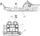
FIG. 6 is a schematic structural diagram of a submarine cable rapid-laying robot in a marine wind farm in a working state;
FIG. 7 is a schematic circuit control diagram of a submarine cable rapid-laying robot for a marine wind farm;
FIG. 8 is a schematic view of a work flow of a submarine cable rapid-laying robot in a marine wind farm;
in the figure, a robot body 1, a buoyancy adjusting mechanism 2, a buoyancy layer 2.1, a buoyancy adjusting device 2.2, a grooving mechanism 3, a spiral grooving device 3.1, a grooving motor 3.2, a grooving electric push rod 3.3, an installation rod 3.4, a laying mechanism 4, a submarine cable conveying device 4.1, a driving wheel 4.11, a driven wheel 4.12, a support column 4.13, a connecting rod 4.14, a compression spring 4.15, a conveying device motor 4.2, an electric push rod 4.3, a double-faced plow 4.4, a burying mechanism 5, a burying rotating wheel 5.1, a burying motor 5.2, a crawler traveling mechanism 6, a crawler driving wheel 6.1, a crawler driven wheel (6.2) 2, a crawler 6.3, a crawler motor 6.4, a propelling mechanism 7, a vertical propeller 7.1, a horizontal propeller 7.2, a submarine cable guide pipe 8, a submarine cable 9, a cabin 10, a front camera 11, a rear camera 12, a searchlight 13, a submarine cable 14 and a DP 15.
Detailed Description
The following describes the embodiments of the present invention in detail with reference to the embodiments, but they are not intended to limit the present invention and are only examples. While the advantages of the invention will be apparent and readily appreciated by the description.
As shown in figure 1, the ocean wind power plant submarine cable quick laying robot comprises a robot body 1, wherein the robot body 1 is of a frame structure formed by connecting aluminum alloy sections, the robot body has good corrosion resistance, the strength of the robot body also meets the design requirements, and the frame is built in a section mode, so that the mass and the resistance of the robot during moving can be effectively reduced. The top of robot 1 is provided with the buoyancy adjustment mechanism 2 that is used for controlling it to float from top to bottom, the side of advancing of robot 1 is provided with the fluting mechanism 3 that is used for going deep into silt and offers the slot, the middle part of robot 1 is provided with the laying mechanism 4 that is used for laying the submarine cable in the slot, the rear side of robot 1 is provided with the burying mechanism 5 that is used for burying silt to the submarine cable in the slot, the below of robot 1 is provided with crawler 6, still be provided with on the robot 1 and be used for providing its advancing mechanism 7 of power.
As shown in fig. 2, the buoyancy adjusting mechanism 2 includes a buoyancy layer 2.1 and a buoyancy adjusting device 2.2, the buoyancy layer 2.1 is disposed on the top of the robot body 1, and the buoyancy adjusting device 2.2 is used for heating the buoyancy layer 2.1 to make it expand to provide buoyancy. By adopting the buoyancy adjusting mechanism 2, the energy consumed by the robot in recycling can be reduced. During recovery, the robot can better reduce energy consumption by adjusting buoyancy. The buoyancy adjusting device 2.2 adopts a thermal expansion method, and adopts an electric heating mode to expand the material to provide buoyancy.
As shown in fig. 3, the slotting mechanism 3 includes a spiral slotting device 3.1, a slotting motor 3.2 and a slotting electric push rod 3.3; the spiral slotting device 3.1 is in a conical shape, and a plurality of circles of spiral blades are arranged on the outer wall of the spiral slotting device 3.1 in a surrounding manner; the slotting motor 3.2 is arranged at the top of the spiral slotting device 3.1 and is used for driving the spiral slotting device to rotate; the slotting electric push rod 3.3 is installed on the advancing side of the robot body 1 through a plurality of installing rods 3.4, and the driving end of the slotting electric push rod 3.3 is connected with the top end of the slotting motor 3.2 and used for driving the spiral slotting device 3.1 and the slotting motor 3.2 to move up and down.
The mode that the fluting mechanism 3 of this embodiment adopted is electronic rotatory fluting, compares traditional high-pressure squirt fluting, has efficient, can not lay the submarine cable to advantages such as water is turbid after the fluting. When the slotting mechanism 3 works, firstly, the slotting motor 3.2 drives the spiral slotting device 3.1 to rotate, then the slotting motor 3.2 extends, under the vertical pressure of the vertical propeller 7.1, the spiral slotting device 3.1 goes deep under silt, and a slot can be opened along with the movement of the robot. During operation, the slotting motor 3.2 drives the spiral slotting device 3.1 to rotate, and silt of the channel can be dispersed to two sides in the rotating process to form a groove meeting the requirements. The depth of the groove is controlled by the grooved electric push rod 3.3, and the longer the electric push rod is, the deeper the groove is.
As shown in fig. 4 and 5, the laying mechanism 4 comprises a submarine cable conveying device 4.1, a conveying device motor 4.2, an electric push rod 4.3 and a double-faced plough 4.4; the submarine cable conveying device 4.1 comprises a driving wheel 4.11 and a driven wheel 4.12 which are used for clamping and conveying a submarine cable 14, and a clamping space for clamping the submarine cable 14 is arranged between the driving wheel 4.11 and the driven wheel 4.12; the driving wheel 4.11 is arranged on a support column 4.13 arranged below the double-sided plough 4.4, and the driven wheel 4.12 is provided with a connecting rod 4.14; one end of the connecting rod 4.14 is rotatably connected with the driven wheel 4.12, and the other end of the connecting rod 4.14 is hinged with the supporting column 4.13; a compression spring 4.15 is connected between the connecting rod 4.14 and the supporting column 4.13; the conveying device motor 4.2 is used for driving the driving wheel 4.11 to rotate and is in clamping fit with the driven wheel 4.12 so as to convey the submarine cable 14; the upper end of the electric push rod 4.3 is arranged on the robot body 1, and the lower end of the electric push rod 4.3 is connected with the double-faced plough 4.4; the double-sided plough 4.4 is arranged above the driving wheel 4.11, and the side wall of the double-sided plough 4.4 extends downwards to two sides of the driving wheel 4.11.
In this embodiment, the sea cable 14 is not directly attached to the robot but placed on the DP ship to reduce the load. In the laying process, the submarine cable penetrates through the submarine cable guide pipe 8 and then penetrates through the submarine cable conveying device 4.1, the conveying device motor 4.2 drives the driving wheel 4.11 to rotate, and the driven wheel 4.12 provides pressure, so that stable conveying of the submarine cable is guaranteed. In order to better realize the laying of the submarine cable, the submarine cable laying device is provided with an electric push rod 4.3, and the submarine cable conveying device 4.1 is directly placed at the bottom of the groove during laying. When the submarine cable 14 is laid, the submarine cable is always positioned at the bottom of the groove, and the later burying is facilitated. The driving wheel adopts a motor driving mode, so that the driving wheel is easily influenced by silt, the driving wheel is easily blocked by the silt entering the driving wheel, and the motor is burnt. Therefore, the structure of the double-sided plough 4.4 is designed, silt rolled into the channel can be cleaned in time, the submarine cable conveying device 4.1 can be protected from being stuck due to the silt, and the driving wheel of the submarine cable conveying device is effectively protected. The electric push rod is used for controlling the laying height so as to ensure that the bottom of the laying device is close to the bottom of the channel, and the cable tensioning effect is better.
In the technical scheme, a submarine cable guide pipe 8 for a submarine cable 14 to penetrate through is arranged above the robot body 1, and submarine cable guide wheels 9 for guiding the submarine cable are arranged on two sides of the submarine cable guide pipe 8; a plurality of sealed cabins 10 are arranged in the robot body 1. A submarine cable guide 8 is arranged above the laying mechanism 4, and a submarine cable 14 passing through the submarine cable guide 8 extends downwards through a clamping space between a driving wheel 4.11 and a driven wheel 4.12 of the laying mechanism 4. In this embodiment, the electrical control system is mainly disposed in two sealed compartments 10, one of which is used to dispose a power conversion device, including an underwater transformer, a voltage stabilizing module and various distribution boxes, to provide electrical energy for various electrical appliances. The other sealed cabin is mainly used for placing an industrial personal computer, a driving module of each device and a video data acquisition box, and is the core for communication at the same bank end and issuing of a robot control command. The working mode is as follows: the industrial personal computer receives the shore end signal, issues an instruction to each driving module, or acquires video information and feeds the video information back to the shore end.
In the technical scheme, the burying mechanism 5 comprises a burying rotating wheel 5.1 and a burying motor 5.2, and the burying motor 5.2 is arranged at the rear side of the robot body 1 and used for driving the burying rotating wheel 5.1 to rotate so as to drive silt to fall into the burying submarine cable in the trench. The burying device is used for burying the cables and is positioned at the tail part of the robot, and each burying rotating wheel is inwards rotated and is arranged at two sides of the channel. When the runner rotates, the silt in the slotting is pushed into the channel again to bury the submarine cable. In the embodiment, the burying device comprises a burying motor 5.2 and a burying rotating wheel 5.1, the burying motor 5.2 drives the burying rotating wheel 5.1 to rotate, and the burying rotating wheel drives silt to fall into the trench, so that the effect of burying is achieved.
In the technical scheme, the crawler traveling mechanism 6 comprises a crawler driving wheel 6.1, a crawler driven wheel 6.2, a crawler 6.3 and a crawler motor 6.4; the crawler motor 6.4 is used for driving the crawler driving wheel 6.1 to rotate, and the crawler driving wheel 6.1 drives the crawler driven wheel 6.2 to rotate through the crawler 6.3. The crawler walking mechanism is a main power source for the robot to move when working. When the device works, the resistance is large, and the requirement cannot be met only by a propulsion system. Therefore, the crawler belt is adopted, and meanwhile, the vertical propeller exerts force, so that sufficient friction force of the crawler belt is guaranteed, and power is provided for work. When the crawler belt type crawler belt device works, the crawler belt motor 6.4 drives the crawler belt driving wheel 6.1 to rotate, immediately, the crawler belt 6.3 is driven to move, and the crawler belt driven wheel 6.2 starts to rotate under the action of crawler belt friction force to play a supporting role.
In the technical scheme, the propulsion mechanism 7 comprises a vertical propeller 7.1 and a horizontal propeller 7.2, and the vertical propeller 7.1 is arranged at the top of the robot body 1 and used for driving the robot body to float upwards and submerge downwards; a horizontal thruster 7.2 is arranged in the middle of the robot body 1 for driving it to move horizontally. The robot of the invention has two sets of power systems, namely a propelling mechanism and a crawler traveling mechanism. When the robot dives, the position is adjusted mainly by a propulsion system, and the propulsion system comprises a vertical propeller 7.1 and a horizontal propeller 7.2. In this embodiment, vertical propeller 7.1 arranges at the top of robot, adopts the mode of arranging perpendicularly, and four altogether except the come-up dive that can control the robot, can also reduce the roll and the pitch of dive in-process. The horizontal propeller 7.2 is used for adjusting the position in the submerging process, the robot is influenced by ocean currents in the submerging process, and the horizontal propeller 7.2 is used for ensuring that the robot can move to a specified position.
In this embodiment, the propulsion mechanism is provided with eight propellers, four of which are vertical propellers and the other four of which are horizontal propellers. The vertical thruster provides power for the robot to float upwards and submerge downwards, and meanwhile, when the robot is laid, vertical thrust is continuously issued, so that the robot is guaranteed to have enough friction force during working. In addition, the robot is provided with the inertial navigation equipment, and the stability of the robot during diving can be ensured by combining the vertical propeller. The horizontal propeller provides power for the horizontal movement of the robot, prevents the robot from moving along with ocean currents when the robot is submerged, and can ensure that the robot moves to a designated working area in the submerging process. The plane motion system adopts a track mode, is suitable for complex conditions of the seabed, is mainly applied to the movement of the robot during laying work, and ensures the friction force between the track and the seabed and a good working environment of the robot by combining the pressure provided by the vertical propeller.
In the above technical solution, the front camera 11 is arranged on the advancing side of the robot body 1, and the rear camera 12 and the searchlight 13 are arranged on the rear side of the robot body 1. After sinking to the bottom, the crawler starts to work, the front-facing camera 11 returns image information, and an operator adjusts the position according to the information. After the burying is finished, the rear camera 12 transmits the buried image back to the bank end, and the worker evaluates the burying effect. In order to better obtain the buried video, the robot is provided with a searchlight 13, which can effectively ensure the definition of the returned image.
The electrical control system of the present invention mainly comprises two parts, which are a power supply system and a communication system, respectively, as shown in fig. 7. Due to the long working time of the robot, if a built-in power supply is adopted, not only the working time is limited, but also the energy consumption is increased due to the increase of the weight. Therefore, the DP ship directly transmits the electric energy to the robot through the umbilical cable by adopting a shore end power supply mode. The transformer and the rectifier and the voltage stabilizer are arranged inside the sealed cabin 10, the transformer reduces 220V alternating current to 36V, the alternating current is converted into direct current through the rectifier, and finally the direct current passes through the voltage stabilizer to output proper voltage. In whole power supply system, some devices consumption is great, needs the stabiliser power supply, for example industrial computer, electricity accent, searchlight etc. to some consumptions less, for example camera, inertial navigation, depth gauge, singlechip etc. can be by the direct power supply of industrial computer.
The communication system is the core of the whole device software system, and the robot adopts a remote control mode. The shore end control core receives wired or wireless remote control equipment information and issues the wired or wireless remote control equipment information to an industrial personal computer of the robot through an umbilical cable. At present, an umbilical cable mode is adopted for communication. After receiving the signal, the industrial personal computer sends an instruction to the single chip microcomputer according to the signal. Then, the singlechip outputs different PWM waves or levels to control the illumination intensity of the motor, the electric push rod and the searchlight. Similarly, the depth gauge returns to the single chip microcomputer after acquiring the underwater pressure, and the single chip microcomputer resolves to obtain accurate depth information and feeds the depth information back to the industrial personal computer. The camera also sends the acquired information to the industrial personal computer. The inertial navigation also outputs angle and acceleration information, and after the industrial personal computer unpacks, angle, acceleration, image and depth information are returned to the shore end control core. After the operator acquires the information, the underwater robot can be better controlled.
The invention relates to a working method of a submarine cable quick laying robot of an ocean wind power plant, which comprises the following steps:
as shown in fig. 6, the DP ship carries the robot and the submarine cable to be laid, and after transporting the robot to a predetermined area, the robot is hoisted. The submarine cable is placed on the DP ship, one end of the submarine cable is placed on a laying device of the robot, and the submarine cable is continuously released when the robot is in operation along with the submergence of the robot into the sea bottom. The entire system includes DP vessel 15, umbilical and robot. The DP ship is responsible for the transportation of the robot and provides electric energy for the robot, and meanwhile, the DP ship is communicated with the robot. The power supply of the robot and the communication with the DP ship are realized through an umbilical cable. During operation, the staff on the DP ship controls the robot through remote control and simultaneously monitors the laying effect of the robot.
The robot and the sea cable are carried by the DP ship and released after being transported to a designated area, wherein one end of the sea cable is fixed on the robot. After release, the robot sinks under the combined action of gravity and the vertical thruster. Meanwhile, the horizontal thruster works to ensure that the robot moves to a position near a designated position. After the bottom is sunk, the crawler starts to work, the front camera transmits back image information, and an operator adjusts the position according to the information. And then, the slotting system starts to work, the electric push rod is extended while the slotting system rotates, the rotary slotting device gradually extends to a specified position, in order to ensure enough pressure and ensure that the slotting device extends into the seabed, and the vertical propeller downwards exerts force to provide enough pressure when the slotting system works. And then, the shore end worker starts to remotely drive the crawler belt to work, the robot slowly moves forwards, and after a small section of position is moved, the submarine cable laying device starts to work. The electric push rod extends to ensure that the submarine cable conveying device is positioned at the bottom of the channel, and a driving wheel of the submarine cable conveying device starts to rotate along with the forward movement of the robot to drive the release of the submarine cable. Next, the burying device begins to work, and under the rotation of motor, the rotation of drive runner propels the slot again with sand to because the robot moving speed is not fast, can lay and bury the effect more effectual observation. Under the control of an operator, the laying can be finished by only driving once according to a preset track. And finally, recovering the robot to complete the operation, wherein the specific flow is shown in fig. 8.
The above description is only an embodiment of the present invention, and it should be noted that any changes or substitutions that can be easily conceived by those skilled in the art within the technical scope of the present invention are included in the protection scope of the present invention, and the rest that is not described in detail is the prior art.
Claims (10)
1. The utility model provides a quick robot that lays of ocean wind-powered electricity generation field seabed submarine cable which characterized in that: including robot body (1), the top of robot body (1) is provided with buoyancy adjustment mechanism (2) that are used for controlling its fluctuation, the side of advancing of robot body (1) is provided with slotted mechanism (3) that are used for going deep into silt and offer the slot, the middle part of robot body (1) is provided with laying mechanism (4) that are used for laying the submarine cable at the ditch inslot, the rear side of robot body (1) is provided with burial mechanism (5) that are used for burying silt to the submarine cable of ditch inslot, the below of robot body (1) is provided with crawler (6), still be provided with advancing mechanism (7) that are used for providing power to it on robot body (1).
2. The marine wind farm submarine cable quick-laying robot according to claim 1, characterized in that: the buoyancy adjusting mechanism (2) comprises a buoyancy layer (2.1) and a buoyancy adjusting device (2.2), the buoyancy layer (2.1) is arranged at the top of the robot body (1), and the buoyancy adjusting device (2.2) is used for heating the buoyancy layer (2.1) to enable the buoyancy layer to expand to provide buoyancy.
3. The marine wind farm submarine cable quick-laying robot according to claim 1, characterized in that: the slotting mechanism (3) comprises a spiral slotting device (3.1), a slotting motor (3.2) and a slotting electric push rod (3.3);
the spiral grooving device (3.1) is in a conical shape, and a plurality of circles of spiral blades are arranged on the outer wall of the spiral grooving device (3.1) in a surrounding manner; the slotting motor (3.2) is arranged at the top of the spiral slotting device (3.1) and is used for driving the spiral slotting device to rotate;
the slotting electric push rod (3.3) is installed on the advancing side of the robot body (1) through a plurality of installing rods (3.4), and the driving end of the slotting electric push rod (3.3) is connected with the top end of the slotting motor (3.2) and used for driving the spiral slotting device (3.1) and the slotting motor (3.2) to move up and down.
4. The marine wind farm submarine cable quick-laying robot according to claim 1 or 2 or 3, characterized in that: the laying mechanism (4) comprises a submarine cable conveying device (4.1), a conveying device motor (4.2), an electric push rod (4.3) and a double-faced plough (4.4);
the submarine cable conveying device (4.1) comprises a driving wheel (4.11) and a driven wheel (4.12) which are used for clamping and conveying submarine cables (14), and a clamping space for clamping the submarine cables (14) is arranged between the driving wheel (4.11) and the driven wheel (4.12); the driving wheel (4.11) is arranged on a support column (4.13) arranged below the double-faced plough (4.4), and the driven wheel (4.12) is provided with a connecting rod (4.14); one end of the connecting rod (4.14) is rotatably connected with the driven wheel (4.12), and the other end of the connecting rod (4.14) is hinged with the supporting column (4.13); a compression spring (4.15) is connected between the connecting rod (4.14) and the supporting column (4.13);
the conveying device motor (4.2) is used for driving the driving wheel (4.11) to rotate and clamping and matching with the driven wheel (4.12) to convey the submarine cable (14); the upper end of the electric push rod (4.3) is arranged on the robot body (1), and the lower end of the electric push rod (4.3) is connected with the double-faced plough (4.4); the double-sided plough (4.4) is arranged above the driving wheel (4.11), and the side wall of the double-sided plough (4.4) extends downwards to the two sides of the driving wheel (4.11).
5. The marine wind farm submarine cable quick-laying robot according to claim 4, characterized in that: a submarine cable guide pipe (8) for a submarine cable (14) to penetrate through is arranged above the robot body (1), and submarine cable guide wheels (9) for guiding the submarine cable are arranged on two sides of the submarine cable guide pipe (8); the robot is characterized in that a plurality of sealed cabins (10) are arranged in the robot body (1).
6. The marine wind farm submarine cable quick-laying robot according to claim 5, characterized in that: the submarine cable guide pipe (8) is arranged above the laying mechanism (4), and a submarine cable (14) penetrating through the submarine cable guide pipe (8) downwards extends through a clamping space between a driving wheel (4.11) and a driven wheel (4.12) of the laying mechanism (4).
7. The marine wind farm submarine cable quick-laying robot according to claim 1 or 2 or 3, characterized in that: bury mechanism (5) including burying runner (5.1) and burying motor (5.2), bury motor (5.2) and set up the rear side that is used for driving at robot body (1) and bury runner (5.1) and rotate in order to drive silt and fall into the inside submarine cable that buries of slot.
8. The marine wind farm submarine cable quick-laying robot according to claim 1 or 2 or 3, characterized in that: the crawler belt walking mechanism (6) comprises a crawler belt driving wheel (6.1), a crawler belt driven wheel (6.2), a crawler belt (6.3) and a crawler belt motor (6.4); the crawler belt motor (6.4) is used for driving the crawler belt driving wheel (6.1) to rotate, and the crawler belt driving wheel (6.1) drives the crawler belt driven wheel (6.2) to rotate through the crawler belt (6.3).
9. The marine wind farm submarine cable quick-laying robot according to claim 1 or 2 or 3, characterized in that: the propulsion mechanism (7) comprises a vertical propeller (7.1) and a horizontal propeller (7.2), and the vertical propeller (7.1) is arranged at the top of the robot body (1) and used for driving the robot body to float upwards and submerge downwards; the horizontal propeller (7.2) is arranged in the middle of the robot body (1) and used for driving the robot body to move horizontally.
10. The marine wind farm submarine cable quick-laying robot according to claim 1 or 2 or 3, characterized in that: the robot is characterized in that a front camera (11) is arranged on the advancing side of the robot body (1), and a rear camera (12) and a searchlight (13) are arranged on the rear side of the robot body (1).
Priority Applications (1)
| Application Number | Priority Date | Filing Date | Title |
|---|---|---|---|
| CN202210524321.6A CN114735173A (en) | 2022-05-13 | 2022-05-13 | Quick laying robot for submarine cables of ocean wind power plant |
Applications Claiming Priority (1)
| Application Number | Priority Date | Filing Date | Title |
|---|---|---|---|
| CN202210524321.6A CN114735173A (en) | 2022-05-13 | 2022-05-13 | Quick laying robot for submarine cables of ocean wind power plant |
Publications (1)
| Publication Number | Publication Date |
|---|---|
| CN114735173A true CN114735173A (en) | 2022-07-12 |
Family
ID=82285858
Family Applications (1)
| Application Number | Title | Priority Date | Filing Date |
|---|---|---|---|
| CN202210524321.6A Pending CN114735173A (en) | 2022-05-13 | 2022-05-13 | Quick laying robot for submarine cables of ocean wind power plant |
Country Status (1)
| Country | Link |
|---|---|
| CN (1) | CN114735173A (en) |
Cited By (2)
| Publication number | Priority date | Publication date | Assignee | Title |
|---|---|---|---|---|
| CN115924036A (en) * | 2023-01-06 | 2023-04-07 | 南通市海洋水建工程有限公司 | Wind power submarine cable laying system and laying method thereof |
| CN116374113A (en) * | 2023-04-24 | 2023-07-04 | 北京琨毅科技有限公司 | Wall-attached walking robot system |
Citations (7)
| Publication number | Priority date | Publication date | Assignee | Title |
|---|---|---|---|---|
| CN106848984A (en) * | 2017-03-16 | 2017-06-13 | 中国船舶科学研究中心(中国船舶重工集团公司第七0二研究所) | A kind of active conveying device that cable winch is spread for seabed |
| CN107800077A (en) * | 2017-11-21 | 2018-03-13 | 烟台大学 | Sea paving cable equipment |
| CN111391985A (en) * | 2020-04-01 | 2020-07-10 | 杭州瑞晟博科技有限公司 | Submarine cable laying device suitable for underwater remote control operation robot |
| CN111576526A (en) * | 2020-06-05 | 2020-08-25 | 江苏科技大学 | Rock-based seabed cable laying device and laying method thereof |
| US20200318314A1 (en) * | 2019-04-08 | 2020-10-08 | Zhoushan Electric Power Supply Company Of State Grid Zhejiang Electric Power Company | Submarine cable trencher |
| EP3800297A1 (en) * | 2019-10-02 | 2021-04-07 | Soil Machine Dynamics Limited | Method and apparatus for inserting an elongate object into a trench in a sea floor |
| KR20220014029A (en) * | 2020-07-28 | 2022-02-04 | 한국로봇융합연구원 | Remotely operated vehicle laying a pipe |
-
2022
- 2022-05-13 CN CN202210524321.6A patent/CN114735173A/en active Pending
Patent Citations (7)
| Publication number | Priority date | Publication date | Assignee | Title |
|---|---|---|---|---|
| CN106848984A (en) * | 2017-03-16 | 2017-06-13 | 中国船舶科学研究中心(中国船舶重工集团公司第七0二研究所) | A kind of active conveying device that cable winch is spread for seabed |
| CN107800077A (en) * | 2017-11-21 | 2018-03-13 | 烟台大学 | Sea paving cable equipment |
| US20200318314A1 (en) * | 2019-04-08 | 2020-10-08 | Zhoushan Electric Power Supply Company Of State Grid Zhejiang Electric Power Company | Submarine cable trencher |
| EP3800297A1 (en) * | 2019-10-02 | 2021-04-07 | Soil Machine Dynamics Limited | Method and apparatus for inserting an elongate object into a trench in a sea floor |
| CN111391985A (en) * | 2020-04-01 | 2020-07-10 | 杭州瑞晟博科技有限公司 | Submarine cable laying device suitable for underwater remote control operation robot |
| CN111576526A (en) * | 2020-06-05 | 2020-08-25 | 江苏科技大学 | Rock-based seabed cable laying device and laying method thereof |
| KR20220014029A (en) * | 2020-07-28 | 2022-02-04 | 한국로봇융합연구원 | Remotely operated vehicle laying a pipe |
Cited By (3)
| Publication number | Priority date | Publication date | Assignee | Title |
|---|---|---|---|---|
| CN115924036A (en) * | 2023-01-06 | 2023-04-07 | 南通市海洋水建工程有限公司 | Wind power submarine cable laying system and laying method thereof |
| CN115924036B (en) * | 2023-01-06 | 2023-11-07 | 南通市海洋水建工程有限公司 | Wind power submarine cable laying system and laying method thereof |
| CN116374113A (en) * | 2023-04-24 | 2023-07-04 | 北京琨毅科技有限公司 | Wall-attached walking robot system |
Similar Documents
| Publication | Publication Date | Title |
|---|---|---|
| CN114735173A (en) | Quick laying robot for submarine cables of ocean wind power plant | |
| AU2013346583B2 (en) | Submerged, tethered water turbine assembly | |
| CA2983451C (en) | Systems and methods for tidal energy conversion and electrical power generation | |
| CN106809358B (en) | Nuclear power station cooling water diversion culvert detects robot system and implementation | |
| CN104806457B (en) | A kind of descending sea-borne wind power generation apparatus | |
| WO2009026620A1 (en) | Marine power generation apparatus using ocean currents | |
| CN111645810B (en) | Multifunctional work ship with buoyancy adjusting carrying platform and operation method thereof | |
| CN108626078B (en) | Auxiliary transportation and erection process for offshore wind turbine Spar type floating foundation barge | |
| CN105197189A (en) | Self-propelled wave force power generation platform and moving and berthing method thereof | |
| CN111791993A (en) | Mother ship supported by manned submersible | |
| US20220259806A1 (en) | Submerged floating rail transit system | |
| CN109323887A (en) | A kind of multi-level propulsion space and time continuous seawater parameter sampling monitoring unmanned boat | |
| US20190085817A1 (en) | Energy conversion device | |
| CN102923261A (en) | Sit-on-bottom type offshore wind turbine installation barge | |
| CN110219652A (en) | Distributed deepsea mining system | |
| CN205186488U (en) | But be applied to heave diving outfit of archipelagic sea | |
| CN110683025A (en) | Ocean current driven anchor mooring type long-endurance glider | |
| US20220242532A1 (en) | Systems and methods for deploying hydroelectric energy systems | |
| CN210370634U (en) | Deep sea underwater unmanned mining system | |
| CN110242303A (en) | Distributed round-the-clock deepsea mining system | |
| CN110775199B (en) | Ocean current energy submerged buoy capable of rising and sinking | |
| CN109178227A (en) | A kind of pin-connected panel sea photovoltaic power generation platform and its construction method | |
| US20110156397A1 (en) | Underwater electrical generator for the harnessing of bidirectional flood currents | |
| CN105221332B (en) | The formula that snorkels tidal current energy generating equipment | |
| CN219750098U (en) | Water floating type photovoltaic platform adopting active positioning |
Legal Events
| Date | Code | Title | Description |
|---|---|---|---|
| PB01 | Publication | ||
| PB01 | Publication | ||
| SE01 | Entry into force of request for substantive examination | ||
| SE01 | Entry into force of request for substantive examination |