CN114733705A - Quenching oiling machine for strip steel production - Google Patents
Quenching oiling machine for strip steel production Download PDFInfo
- Publication number
- CN114733705A CN114733705A CN202210267128.9A CN202210267128A CN114733705A CN 114733705 A CN114733705 A CN 114733705A CN 202210267128 A CN202210267128 A CN 202210267128A CN 114733705 A CN114733705 A CN 114733705A
- Authority
- CN
- China
- Prior art keywords
- oil
- fixedly connected
- strip steel
- face
- quenching
- Prior art date
- Legal status (The legal status is an assumption and is not a legal conclusion. Google has not performed a legal analysis and makes no representation as to the accuracy of the status listed.)
- Pending
Links
- 229910000831 Steel Inorganic materials 0.000 title claims abstract description 65
- 239000010959 steel Substances 0.000 title claims abstract description 65
- 238000010791 quenching Methods 0.000 title claims abstract description 16
- 230000000171 quenching effect Effects 0.000 title claims abstract description 16
- 238000004519 manufacturing process Methods 0.000 title claims abstract description 9
- 238000003860 storage Methods 0.000 claims abstract description 38
- 239000002699 waste material Substances 0.000 claims description 22
- 238000013016 damping Methods 0.000 claims description 9
- 238000007599 discharging Methods 0.000 claims description 6
- 238000009826 distribution Methods 0.000 claims description 3
- 230000008878 coupling Effects 0.000 claims 3
- 238000010168 coupling process Methods 0.000 claims 3
- 238000005859 coupling reaction Methods 0.000 claims 3
- 239000003921 oil Substances 0.000 abstract description 98
- 230000000694 effects Effects 0.000 abstract description 18
- 239000010687 lubricating oil Substances 0.000 abstract description 17
- 238000000034 method Methods 0.000 abstract description 8
- 230000009286 beneficial effect Effects 0.000 description 1
- 239000011248 coating agent Substances 0.000 description 1
- 238000000576 coating method Methods 0.000 description 1
- 238000005516 engineering process Methods 0.000 description 1
- 238000009776 industrial production Methods 0.000 description 1
- 230000002452 interceptive effect Effects 0.000 description 1
- 238000005304 joining Methods 0.000 description 1
- 239000002184 metal Substances 0.000 description 1
- 238000005096 rolling process Methods 0.000 description 1
Images


Classifications
-
- B—PERFORMING OPERATIONS; TRANSPORTING
- B05—SPRAYING OR ATOMISING IN GENERAL; APPLYING FLUENT MATERIALS TO SURFACES, IN GENERAL
- B05C—APPARATUS FOR APPLYING FLUENT MATERIALS TO SURFACES, IN GENERAL
- B05C5/00—Apparatus in which liquid or other fluent material is projected, poured or allowed to flow on to the surface of the work
-
- B—PERFORMING OPERATIONS; TRANSPORTING
- B05—SPRAYING OR ATOMISING IN GENERAL; APPLYING FLUENT MATERIALS TO SURFACES, IN GENERAL
- B05C—APPARATUS FOR APPLYING FLUENT MATERIALS TO SURFACES, IN GENERAL
- B05C11/00—Component parts, details or accessories not specifically provided for in groups B05C1/00 - B05C9/00
- B05C11/02—Apparatus for spreading or distributing liquids or other fluent materials already applied to a surface ; Controlling means therefor; Control of the thickness of a coating by spreading or distributing liquids or other fluent materials already applied to the coated surface
- B05C11/023—Apparatus for spreading or distributing liquids or other fluent materials already applied to a surface
-
- B—PERFORMING OPERATIONS; TRANSPORTING
- B05—SPRAYING OR ATOMISING IN GENERAL; APPLYING FLUENT MATERIALS TO SURFACES, IN GENERAL
- B05C—APPARATUS FOR APPLYING FLUENT MATERIALS TO SURFACES, IN GENERAL
- B05C11/00—Component parts, details or accessories not specifically provided for in groups B05C1/00 - B05C9/00
- B05C11/10—Storage, supply or control of liquid or other fluent material; Recovery of excess liquid or other fluent material
- B05C11/1039—Recovery of excess liquid or other fluent material; Controlling means therefor
-
- B—PERFORMING OPERATIONS; TRANSPORTING
- B05—SPRAYING OR ATOMISING IN GENERAL; APPLYING FLUENT MATERIALS TO SURFACES, IN GENERAL
- B05C—APPARATUS FOR APPLYING FLUENT MATERIALS TO SURFACES, IN GENERAL
- B05C13/00—Means for manipulating or holding work, e.g. for separate articles
- B05C13/02—Means for manipulating or holding work, e.g. for separate articles for particular articles
-
- B—PERFORMING OPERATIONS; TRANSPORTING
- B05—SPRAYING OR ATOMISING IN GENERAL; APPLYING FLUENT MATERIALS TO SURFACES, IN GENERAL
- B05C—APPARATUS FOR APPLYING FLUENT MATERIALS TO SURFACES, IN GENERAL
- B05C9/00—Apparatus or plant for applying liquid or other fluent material to surfaces by means not covered by any preceding group, or in which the means of applying the liquid or other fluent material is not important
- B05C9/04—Apparatus or plant for applying liquid or other fluent material to surfaces by means not covered by any preceding group, or in which the means of applying the liquid or other fluent material is not important for applying liquid or other fluent material to opposite sides of the work
-
- C—CHEMISTRY; METALLURGY
- C21—METALLURGY OF IRON
- C21D—MODIFYING THE PHYSICAL STRUCTURE OF FERROUS METALS; GENERAL DEVICES FOR HEAT TREATMENT OF FERROUS OR NON-FERROUS METALS OR ALLOYS; MAKING METAL MALLEABLE, e.g. BY DECARBURISATION OR TEMPERING
- C21D1/00—General methods or devices for heat treatment, e.g. annealing, hardening, quenching or tempering
- C21D1/62—Quenching devices
-
- C—CHEMISTRY; METALLURGY
- C21—METALLURGY OF IRON
- C21D—MODIFYING THE PHYSICAL STRUCTURE OF FERROUS METALS; GENERAL DEVICES FOR HEAT TREATMENT OF FERROUS OR NON-FERROUS METALS OR ALLOYS; MAKING METAL MALLEABLE, e.g. BY DECARBURISATION OR TEMPERING
- C21D9/00—Heat treatment, e.g. annealing, hardening, quenching or tempering, adapted for particular articles; Furnaces therefor
- C21D9/52—Heat treatment, e.g. annealing, hardening, quenching or tempering, adapted for particular articles; Furnaces therefor for wires; for strips ; for rods of unlimited length
-
- Y—GENERAL TAGGING OF NEW TECHNOLOGICAL DEVELOPMENTS; GENERAL TAGGING OF CROSS-SECTIONAL TECHNOLOGIES SPANNING OVER SEVERAL SECTIONS OF THE IPC; TECHNICAL SUBJECTS COVERED BY FORMER USPC CROSS-REFERENCE ART COLLECTIONS [XRACs] AND DIGESTS
- Y02—TECHNOLOGIES OR APPLICATIONS FOR MITIGATION OR ADAPTATION AGAINST CLIMATE CHANGE
- Y02P—CLIMATE CHANGE MITIGATION TECHNOLOGIES IN THE PRODUCTION OR PROCESSING OF GOODS
- Y02P10/00—Technologies related to metal processing
- Y02P10/20—Recycling
Landscapes
- Chemical & Material Sciences (AREA)
- Engineering & Computer Science (AREA)
- Physics & Mathematics (AREA)
- Thermal Sciences (AREA)
- Crystallography & Structural Chemistry (AREA)
- Mechanical Engineering (AREA)
- Materials Engineering (AREA)
- Metallurgy (AREA)
- Organic Chemistry (AREA)
- Coating Apparatus (AREA)
Abstract
The invention discloses a quenching and oiling machine for strip steel production, which belongs to the technical field of strip steel production and comprises an oiling machine body and an oil storage tank, wherein the left side of the upper end surface of the oiling machine body is fixedly connected with the oil storage tank, the oil storage tank is internally provided with an oil storage cavity, both sides of the oiling machine body are respectively provided with a first side open slot, the oiling machine body is internally provided with an oiling cavity, the left side of the upper end surface of the inner side of the oiling cavity is fixedly connected with an inner connecting plate, the lower end surface of the inner connecting plate is fixedly connected with an oil flow pipe, the oiling cavity is internally provided with an inner fixing plate, the upper end surface of the inner fixing plate is provided with a through hole, and the right sides of the front end surface and the rear end surface of the inner fixing plate are respectively fixedly connected with a second side connecting plate. The lubricating oil can be uniformly coated on the outer surface of the band steel, so that the effect of stable operation of the oil troweling machine body in the using process is achieved.
Description
Technical Field
The invention relates to the technical field of strip steel production, in particular to a quenching oiling machine for strip steel production.
Background
The strip steel is a narrow and long steel plate produced by various steel rolling enterprises in order to meet the requirements of different industrial departments on industrial production of various types of metal or mechanical products. The strip steel is also called steel strip, the width is within 1300mm, the length is slightly different according to the size of each roll, and a oiling machine is needed when the strip steel is produced.
The problem of uneven coating of lubricating oil on the outer surface of the strip steel in the prior art can cause the phenomenon that the surface of the strip steel is not lubricated in the subsequent production process, and finally the result that the oil smearing machine runs unstably in the working process is caused
The prior art has the problem that the prior device carries out oiling on band steel pre-clamping with different thicknesses, so that the phenomenon that band steel with one size needs to be matched with an oiling machine is caused, and finally, a factory needs to spend a large amount of funds to purchase oiling machines with other sizes.
Disclosure of Invention
The invention aims to provide a quenching oil smearing machine for producing strip steel, which aims to solve the problems in the background technology.
In order to achieve the purpose, the invention provides the following technical scheme:
a quenching and oiling machine for strip steel production comprises an oiling machine body and an oil storage tank, wherein the oil storage tank is fixedly connected to the left side of the upper end face of the oiling machine body, an oil storage cavity is formed in the oil storage tank, first side open slots are formed in two sides of the oiling machine body, an oiling cavity is formed in the oiling machine body, an inner connecting plate is fixedly connected to the left side of the upper end face of the inner side of the oiling cavity, a flow oil pipe is fixedly connected to the lower end face of the inner connecting plate, the flow oil pipe is provided with a plurality of flow oil pipes, an inner fixing plate is arranged in the oiling cavity, a through hole is formed in the upper end face of the inner fixing plate, a second side connecting plate is fixedly connected to the right side of the front end face and the rear end face of the inner fixing plate, a connecting shaft is rotatably connected between the second side connecting plate and the oiling cavity, a rotating roller is fixedly connected to the outer circumferential face of the connecting shaft, a fixing brush is fixedly connected to the outer circumferential face of the rotating roller, according to the invention, the oiling machine body, the oil storage tank, the oil storage cavity, the first side open slot, the oil smearing cavity, the inner connecting plate, the oil flow pipe, the inner fixing plate, the through hole, the second side connecting plate, the connecting shaft, the rotating roller and the fixing brush are arranged, so that one end of the strip steel can be inserted into the first side open slot on the left side, the strip steel moves rightwards on the inner fixing plate, meanwhile, lubricating oil in the oil storage cavity flows to two side surfaces of the strip steel from the oil flow pipe, the strip steel moves rightwards all the time, when the strip steel moves to be in contact with the fixing brush, the fixing brush uniformly coats the lubricating oil on the outer surface of the strip steel, and the effect that the lubricating oil can be uniformly coated on the outer surface of the strip steel so as to achieve stable operation of the oiling machine body in the using process is achieved.
As a further scheme of the invention: the band steel oiling machine is characterized in that inner open grooves are formed in the front end face and the rear end face of each first side open groove, a plurality of connecting springs are fixedly connected to the inner end faces of the inner open grooves, outer fixing plates are fixedly connected to the outer ends of the connecting springs, rotating shafts are rotatably connected between the outer fixing plates, and rollers are fixedly connected to the outer circumferential faces of the rotating shafts.
As a still further scheme of the invention: the spout has been seted up to the terminal surface under the chamber of applying oil, sliding connection has the slider in the spout, slider up end fixedly connected with waste oil collection box is provided with spout, slider and waste oil collection box and can reach the effect of collecting the waste oil that flows down from the through-hole.
As a still further scheme of the invention: second side open slot has been seted up to machine of plastering a trowel body left end face downside, second side open slot downside rotates and is connected with the damping pivot, the outer periphery fixedly connected with of damping pivot opens and closes the door, the outer terminal surface fixedly connected with first in command of opening and closing the door is provided with second side open slot, damping pivot, opens and closes door and first in command and can reach the effect of conveniently taking out waste oil collection box.
As a still further scheme of the invention: the size of the upper end of the waste oil collecting box is larger than the distribution size of the through holes, so that the effect that waste oil flowing down through the holes enters the waste oil collecting box is ensured.
As a still further scheme of the invention: the front end face of the waste oil collecting box is fixedly connected with a second handle, and the second handle is arranged to achieve the effect of conveniently applying work to the waste oil collecting box.
As a still further scheme of the invention: the size of the sliding block is matched with that of the sliding groove, so that the sliding block is prevented from interfering in the sliding groove.
As a still further scheme of the invention: the oil smearing machine is characterized in that first side connecting plates are fixedly connected to two side faces of the oil smearing machine body respectively, a plurality of first side connecting plates are arranged, each first side connecting plate is provided with a screw hole in the upper end face, each screw hole is provided with a bolt, and the effect of fixedly connecting the oil smearing machine body and an external device can be achieved by arranging the first side connecting plates, the screw holes and the bolts.
As a still further scheme of the invention: the oil storage tank up end fixedly connected with adds oil pipe, oil storage tank rear end fixedly connected with puts oil pipe, it is provided with the ball valve to put the oil pipe outside, is provided with and adds oil pipe, puts oil pipe and ball valve and can reach the effect of carrying out the joining of lubricating oil circulation to the oil storage tank.
Compared with the prior art, the invention has the beneficial effects that:
1. in the invention, an oil storage tank is fixedly connected with the left side of the upper end surface of an oil smearing machine body, an oil storage cavity is arranged in the oil storage tank, first side open slots are respectively arranged at the two sides of the oil smearing machine body, an oil smearing cavity is arranged in the oil smearing machine body, an inner connecting plate is fixedly connected with the left side of the upper end surface at the inner side of the oil smearing cavity, a plurality of flow oil pipes are fixedly connected with the lower end surface of the inner connecting plate, an inner fixing plate is arranged in the oil smearing cavity, through holes are arranged at the upper end surface of the inner fixing plate, second side connecting plates are fixedly connected with the right sides of the front and rear end surfaces of the inner fixing plate, a connecting shaft is rotatably connected between the second side connecting plates and the oil smearing cavity, a rotating roller is fixedly connected with the outer circumferential surface of the connecting shaft, and a fixed brush is fixedly connected with the outer circumferential surface of the rotating roller, one end of strip steel is inserted from the first side open slot at the left side, the strip steel moves to the right on the inner fixing plate, and meanwhile, lubricating oil in the oil storage cavity flows to the two side faces of the strip steel from the oil flow pipe, the strip steel moves rightwards all the time, when the strip steel moves to be in contact with the fixed hairbrush, the fixed hairbrush uniformly coats the lubricating oil on the outer surface of the strip steel, the problem that the lubricating oil on the outer surface of the strip steel is not uniformly coated is solved, and the effect that the lubricating oil can be uniformly coated on the outer surface of the strip steel so as to achieve the stable operation of the oil trowelling machine body in the using process is achieved.
2. According to the invention, the inner open slots are formed in the front end face and the rear end face of each first side open slot, the inner end faces of the inner open slots are fixedly connected with the connecting springs, the outer ends of the connecting springs are fixedly connected with the outer fixing plates, the rotating shafts are rotatably connected between the outer fixing plates, and the rollers are fixedly connected on the outer circumferential surfaces of the rotating shafts.
Drawings
FIG. 1 is a schematic perspective view of the present invention;
FIG. 2 is a schematic view of the structure of the oil pipe of the present invention;
FIG. 3 is a schematic cross-sectional view of the inner open slot of the present invention;
FIG. 4 is an enlarged view of the structure at A in FIG. 3 according to the present invention;
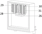
FIG. 5 is a schematic cross-sectional view of the connecting shaft according to the present invention;
fig. 6 is a schematic structural view of the ball valve of the present invention.
In the figure: 1. an oiling machine body; 2. an oil cavity is smeared; 3. an oil storage tank; 4. a first side connecting plate; 5. a screw hole; 6. a bolt; 7. a first side open slot; 8. an inner open slot; 9. a connecting spring; 10. an outer fixing plate; 11. a rotating shaft; 12. a roller; 13. a ball valve; 14. a second side open slot; 15. a damping rotating shaft; 16. opening and closing the door; 17. a first handle; 18. a chute; 19. a slider; 20. a waste oil collection box; 21. a second handle; 22. an oil storage chamber; 23. an oil filling pipe; 24. an inner connection plate; 25. a flow pipe; 26. an inner fixing plate; 27. through the hole; 28. a second side connection plate; 29. a connecting shaft; 30. a rotating roller; 31. fixing the brush; 32. and (5) discharging the oil pipe.
Detailed Description
The technical solutions in the embodiments of the present invention will be clearly and completely described below with reference to the drawings in the embodiments of the present invention, and it is obvious that the described embodiments are only a part of the embodiments of the present invention, and not all of the embodiments. All other embodiments, which can be derived by a person skilled in the art from the embodiments given herein without making any creative effort, shall fall within the protection scope of the present invention.
Referring to fig. 1 to 6, in the embodiment of the present invention, a quenching and oiling machine for producing strip steel includes an oiling machine body 1 and an oil storage tank 3, the oil storage tank 3 is fixedly connected to the left side of the upper end surface of the oiling machine body 1, an oil storage chamber 22 is formed in the oil storage tank 3, first side open slots 7 are formed in both sides of the oiling machine body 1, an oiling chamber 2 is formed in the oiling machine body 1, an inner connecting plate 24 is fixedly connected to the left side of the upper end surface of the inner side of the oiling chamber 2, a plurality of oil flow pipes 25 are fixedly connected to the lower end surface of the inner connecting plate 24, an inner fixing plate 26 is arranged in the oiling chamber 2, a through hole 27 is formed in the upper end surface of the inner fixing plate 26, a second side connecting plate 28 is fixedly connected to the right side of the front and rear end surfaces of the inner fixing plate 26, a connecting shaft 29 is rotatably connected between the second side connecting plate 28 and the oiling chamber 2, and a rotating roller 30 is fixedly connected to the outer circumferential surface of the connecting shaft 29, the outer circumference of the rotating roller 30 is fixedly connected with a fixed brush 31, the invention can insert one end of the strip steel from the left first side open slot 7 by arranging the oiling machine body 1, the oil storage tank 3, the oil storage cavity 22, the first side open slot 7, the oiling cavity 2, the inner connecting plate 24, the oil flow pipe 25, the inner fixing plate 26, the through hole 27, the second side connecting plate 28, the connecting shaft 29, the rotating roller 30 and the fixed brush 31, the strip steel moves to the right on the inner fixing plate 26, at the same time, the lubricating oil in the oil storage chamber 22 flows from the oil flow pipe 25 to both side surfaces of the strip steel, the strip steel moves right, when the strip steel moves to contact with the fixed hairbrush 31, the fixed hairbrush 31 uniformly coats the lubricating oil on the outer surface of the strip steel, so that the lubricating oil can be uniformly coated on the outer surface of the strip steel, and the effect of stable operation of the oil trowelling machine body 1 in the using process is achieved.
The strip steel oil smearing device comprises a first side open slot 7, a plurality of connecting springs 9, an outer fixing plate 10, a rotating shaft 11 and rollers 12, wherein the front end face and the rear end face of the first side open slot 7 are respectively provided with an inner open slot 8, the inner end face of the inner open slot 8 is fixedly connected with the connecting springs 9, the outer end of each connecting spring 9 is fixedly connected with the outer fixing plate 10, the rotating shaft 11 is rotatably connected between the outer fixing plates 10, and the outer circumferential face of the rotating shaft 11 is fixedly connected with the rollers 12;
the lower end surface of the oil smearing cavity 2 is provided with a sliding groove 18, a sliding block 19 is connected in the sliding groove 18 in a sliding mode, the upper end surface of the sliding block 19 is fixedly connected with a waste oil collecting box 20, and the sliding groove 18, the sliding block 19 and the waste oil collecting box 20 are arranged to achieve the effect of collecting waste oil flowing down from the through hole 27;
a second side opening slot 14 is formed in the lower side of the left end face of the oiling machine body 1, a damping rotating shaft 15 is rotatably connected to the lower side of the second side opening slot 14, an opening and closing door 16 is fixedly connected to the outer circumferential face of the damping rotating shaft 15, a first handle 17 is fixedly connected to the outer end face of the opening and closing door 16, and the effect of conveniently taking out the waste oil collecting box 20 can be achieved by arranging the second side opening slot 14, the damping rotating shaft 15, the opening and closing door 16 and the first handle 17;
the size of the upper end of the waste oil collecting box 20 is larger than the distribution size of the through holes 27, so that the effect of enabling the waste oil flowing down through the through holes 27 to enter the waste oil collecting box 20 is ensured;
the front end face of the waste oil collecting box 20 is fixedly connected with a second handle 21, and the second handle 21 is arranged to achieve the effect of conveniently doing work on the waste oil collecting box 20;
the size of the sliding block 19 is matched with that of the sliding groove 18, so that the sliding block 19 is ensured not to generate an interference phenomenon in the sliding groove 18;
the two side surfaces of the oil applying machine body 1 are fixedly connected with first side connecting plates 4, a plurality of first side connecting plates 4 are arranged, the upper end surface of each first side connecting plate 4 is provided with a screw hole 5, a bolt 6 is arranged in each screw hole 5, and the first side connecting plates 4, the screw holes 5 and the bolts 6 are arranged to achieve the effect of fixedly connecting the oil applying machine body 1 with an external device;
the oil filling pipe 23 is fixedly connected to the upper end face of the oil storage tank 3, the oil discharging pipe 32 is fixedly connected to the rear end face of the oil storage tank 3, the ball valve 13 is arranged on the outer side of the oil discharging pipe 32, and the oil filling pipe 23, the oil discharging pipe 32 and the ball valve 13 are arranged to achieve the effect of circularly adding lubricating oil into the oil storage tank 3.
The working principle of the invention is as follows: before the oiling action is carried out on the strip steel, the strip steel is inserted into the inner opening groove 8 in an erecting way, the strip steel contacts with the roller 12 on the circumferential surface, in the process of moving right, the roller 12 always contacts with the outer surface of the belt steel, so as to achieve the effect of being suitable for the oiling operation of the belt steel with different thicknesses, in the process of oiling, one end of the strip steel is inserted from the left side first side open slot 7, the strip steel moves rightwards on the inner fixing plate 26, at the same time, the lubricating oil in the oil storage chamber 22 flows from the oil flow pipe 25 to both side surfaces of the strip steel, the strip steel moves right, when the strip steel moves to contact with the fixed hairbrush 31, the fixed hairbrush 31 uniformly coats the lubricating oil on the outer surface of the strip steel, so that the lubricating oil can be uniformly coated on the outer surface of the strip steel, and the effect of stable operation of the oil trowelling machine body 1 in the using process is achieved.
The above description is only for the preferred embodiment of the present invention, but the scope of the present invention is not limited thereto, and any person skilled in the art should be considered to be within the technical scope of the present invention, and the technical solutions and the inventive concepts thereof according to the present invention should be equivalent or changed within the scope of the present invention.
Claims (9)
1. The utility model provides a band steel production is with quenching oiling machine, includes oiling machine body (1) and oil storage tank (3), its characterized in that: the oil applying machine is characterized in that an oil storage tank (3) is fixedly connected to the left side of the upper end face of the oil applying machine body (1), an oil storage cavity (22) is formed in the oil storage tank (3), first side open grooves (7) are formed in the two sides of the oil applying machine body (1), an oil applying cavity (2) is formed in the oil applying machine body (1), an inner connecting plate (24) is fixedly connected to the left side of the inner upper end face of the oil applying cavity (2), a plurality of oil flowing pipes (25) are fixedly connected to the lower end face of the inner connecting plate (24), an inner fixing plate (26) is arranged in the oil applying cavity (2), a through hole (27) is formed in the upper end face of the inner fixing plate (26), a second side connecting plate (28) is fixedly connected to the right side of the front end face and back of the inner fixing plate (26), and a connecting shaft (29) is rotatably connected between the second side connecting plate (28) and the oil applying cavity (2), the outer circumferential surface of the connecting shaft (29) is fixedly connected with a rotating roller (30), and the outer circumferential surface of the rotating roller (30) is fixedly connected with a fixed hairbrush (31).
2. The quenching oiling machine for producing strip steel according to claim 1, which is characterized in that: interior open slot (8) have all been seted up to terminal surface around first side open slot (7), terminal surface fixedly connected with coupling spring (9) in interior open slot (8), coupling spring (9) are provided with a plurality ofly, coupling spring (9) outer end fixedly connected with outer fixed plate (10), it is connected with axis of rotation (11) to rotate between outer fixed plate (10), axis of rotation (11) outer periphery fixedly connected with gyro wheel (12).
3. The quenching oiling machine for producing strip steel according to claim 1, which is characterized in that: the lower end face of the oil smearing cavity (2) is provided with a sliding groove (18), the sliding groove (18) is connected with a sliding block (19) in a sliding mode, and the upper end face of the sliding block (19) is fixedly connected with a waste oil collecting box (20).
4. The quenching oiling machine for producing strip steel according to claim 1, which is characterized in that: second side open slot (14) have been seted up to oiling machine body (1) left end face downside, second side open slot (14) downside rotates and is connected with damping pivot (15), outer periphery fixedly connected with of damping pivot (15) opens and shuts door (16), the outer terminal surface fixedly connected with first in command (17) of opening and shutting door (16).
5. The quenching oiling machine for producing strip steel according to claim 3, which is characterized in that: the size of the upper end of the waste oil collecting box (20) is larger than the distribution size of the through holes (27).
6. The quenching oiling machine for producing strip steel according to claim 3, which is characterized in that: the front end face of the waste oil collecting box (20) is fixedly connected with a second handle (21).
7. The quenching and oil smearing machine for producing the strip steel as claimed in claim 3, wherein: the size of the sliding block (19) is matched with that of the sliding groove (18).
8. The quenching oiling machine for producing strip steel according to claim 1, which is characterized in that: the oil applying machine is characterized in that first side connecting plates (4) are fixedly connected to two side faces of the oil applying machine body (1), a plurality of screw holes (5) are formed in the first side connecting plates (4), each screw hole (5) is formed in the upper end face of each first side connecting plate (4), and bolts (6) are arranged in the screw holes (5).
9. The quenching oiling machine for producing strip steel according to claim 1, which is characterized in that: the oil storage tank is characterized in that an oil filling pipe (23) is fixedly connected to the upper end face of the oil storage tank (3), an oil discharging pipe (32) is fixedly connected to the rear end face of the oil storage tank (3), and a ball valve (13) is arranged on the outer side of the oil discharging pipe (32).
Priority Applications (1)
| Application Number | Priority Date | Filing Date | Title |
|---|---|---|---|
| CN202210267128.9A CN114733705A (en) | 2022-03-17 | 2022-03-17 | Quenching oiling machine for strip steel production |
Applications Claiming Priority (1)
| Application Number | Priority Date | Filing Date | Title |
|---|---|---|---|
| CN202210267128.9A CN114733705A (en) | 2022-03-17 | 2022-03-17 | Quenching oiling machine for strip steel production |
Publications (1)
| Publication Number | Publication Date |
|---|---|
| CN114733705A true CN114733705A (en) | 2022-07-12 |
Family
ID=82277754
Family Applications (1)
| Application Number | Title | Priority Date | Filing Date |
|---|---|---|---|
| CN202210267128.9A Pending CN114733705A (en) | 2022-03-17 | 2022-03-17 | Quenching oiling machine for strip steel production |
Country Status (1)
| Country | Link |
|---|---|
| CN (1) | CN114733705A (en) |
Citations (24)
| Publication number | Priority date | Publication date | Assignee | Title |
|---|---|---|---|---|
| CN104271258A (en) * | 2012-05-09 | 2015-01-07 | 杰富意钢铁株式会社 | Slurry coating device and slurry coating method |
| CN107116006A (en) * | 2017-05-17 | 2017-09-01 | 河钢股份有限公司邯郸分公司 | A kind of automatic brush-coating device of heavy rail steel billet anticreep carbon coating |
| CN206778769U (en) * | 2017-04-19 | 2017-12-22 | 天津市锴瑞金属制品股份有限公司 | A kind of chain production oiling device |
| CN208771770U (en) * | 2018-08-21 | 2019-04-23 | 河南省君煜实业有限公司 | A kind of artificial board double-side automatic double surface gluer |
| CN209490999U (en) * | 2018-12-07 | 2019-10-15 | 苏州锦宇钢结构有限公司 | A kind of steel plate paint-spraying device |
| CN209597541U (en) * | 2019-01-24 | 2019-11-08 | 金溪县皇族家居有限公司 | A kind of automatic painting device for mahogany furniture production |
| CN110787953A (en) * | 2019-11-18 | 2020-02-14 | 安徽永恒动力科技有限公司 | Efficient smear machine for lead-acid storage battery plate deleting and processing |
| CN210279650U (en) * | 2019-05-31 | 2020-04-10 | 嘉兴市驰宇五金有限公司 | Equipment is paintd to resistant type draw-bar box pull rod surface lubricating oil |
| CN111013917A (en) * | 2019-12-10 | 2020-04-17 | 常州曙光化工厂 | Rust preventive oil feeding device for strip steel production |
| CN210546102U (en) * | 2019-09-21 | 2020-05-19 | 东阳市诰源闪光材料有限公司 | Reflecting material coating machine |
| CN210546086U (en) * | 2019-09-12 | 2020-05-19 | 烟台凌云玻璃纤维制品有限公司 | Grid cloth printing device |
| CN211463691U (en) * | 2019-12-18 | 2020-09-11 | 新余市永利带钢有限公司 | Quenching oiling machine for strip steel production |
| CN111842068A (en) * | 2020-07-09 | 2020-10-30 | 山东立威微波设备有限公司 | Stepless UV curing device |
| CN111957523A (en) * | 2020-08-11 | 2020-11-20 | 韶关市华思迅飞信息科技有限公司 | Detection oil smearing mechanism of automatic production line of big data slide rail and use method |
| CN112170118A (en) * | 2020-09-30 | 2021-01-05 | 萧县冠达新型墙体材料有限责任公司 | A prevent static paint and wipe equipment of scribbling for preventing static panel processing |
| CN213051268U (en) * | 2020-07-07 | 2021-04-27 | 广州市研成金属制品有限公司 | Coiled material oil lubricating and recycling device |
| CN113560251A (en) * | 2021-07-05 | 2021-10-29 | 温州市中心医院 | Medical instrument disinfecting equipment with classifying and disinfecting functions |
| CN113600441A (en) * | 2021-09-02 | 2021-11-05 | 孙斌 | Production method of anti-adhesive-release laminated glass |
| CN214744880U (en) * | 2021-04-19 | 2021-11-16 | 浙江天旭机电设备有限公司 | Petrochemical machinery lubricating oil station |
| CN215051617U (en) * | 2021-01-26 | 2021-12-07 | 嘉兴市金荣科技股份有限公司 | Silicone oil feeding device for release paper |
| CN215088136U (en) * | 2020-09-23 | 2021-12-10 | 赛莱斯泵业(大连)有限公司 | Bearing ring production that practicality is strong is with device of applying oil |
| CN215197898U (en) * | 2021-05-13 | 2021-12-17 | 福建辰曦建筑装饰工程有限公司 | Decorate high-efficient rubber coating device that plywood was used |
| CN215586999U (en) * | 2021-08-27 | 2022-01-21 | 温州市玖辉工艺品有限公司 | Even rubber coating device of sticker |
| CN215784628U (en) * | 2021-07-26 | 2022-02-11 | 烟台大信包装有限公司 | Flocking machine that possesses unnecessary fine hair material absorption memory function |
-
2022
- 2022-03-17 CN CN202210267128.9A patent/CN114733705A/en active Pending
Patent Citations (24)
| Publication number | Priority date | Publication date | Assignee | Title |
|---|---|---|---|---|
| CN104271258A (en) * | 2012-05-09 | 2015-01-07 | 杰富意钢铁株式会社 | Slurry coating device and slurry coating method |
| CN206778769U (en) * | 2017-04-19 | 2017-12-22 | 天津市锴瑞金属制品股份有限公司 | A kind of chain production oiling device |
| CN107116006A (en) * | 2017-05-17 | 2017-09-01 | 河钢股份有限公司邯郸分公司 | A kind of automatic brush-coating device of heavy rail steel billet anticreep carbon coating |
| CN208771770U (en) * | 2018-08-21 | 2019-04-23 | 河南省君煜实业有限公司 | A kind of artificial board double-side automatic double surface gluer |
| CN209490999U (en) * | 2018-12-07 | 2019-10-15 | 苏州锦宇钢结构有限公司 | A kind of steel plate paint-spraying device |
| CN209597541U (en) * | 2019-01-24 | 2019-11-08 | 金溪县皇族家居有限公司 | A kind of automatic painting device for mahogany furniture production |
| CN210279650U (en) * | 2019-05-31 | 2020-04-10 | 嘉兴市驰宇五金有限公司 | Equipment is paintd to resistant type draw-bar box pull rod surface lubricating oil |
| CN210546086U (en) * | 2019-09-12 | 2020-05-19 | 烟台凌云玻璃纤维制品有限公司 | Grid cloth printing device |
| CN210546102U (en) * | 2019-09-21 | 2020-05-19 | 东阳市诰源闪光材料有限公司 | Reflecting material coating machine |
| CN110787953A (en) * | 2019-11-18 | 2020-02-14 | 安徽永恒动力科技有限公司 | Efficient smear machine for lead-acid storage battery plate deleting and processing |
| CN111013917A (en) * | 2019-12-10 | 2020-04-17 | 常州曙光化工厂 | Rust preventive oil feeding device for strip steel production |
| CN211463691U (en) * | 2019-12-18 | 2020-09-11 | 新余市永利带钢有限公司 | Quenching oiling machine for strip steel production |
| CN213051268U (en) * | 2020-07-07 | 2021-04-27 | 广州市研成金属制品有限公司 | Coiled material oil lubricating and recycling device |
| CN111842068A (en) * | 2020-07-09 | 2020-10-30 | 山东立威微波设备有限公司 | Stepless UV curing device |
| CN111957523A (en) * | 2020-08-11 | 2020-11-20 | 韶关市华思迅飞信息科技有限公司 | Detection oil smearing mechanism of automatic production line of big data slide rail and use method |
| CN215088136U (en) * | 2020-09-23 | 2021-12-10 | 赛莱斯泵业(大连)有限公司 | Bearing ring production that practicality is strong is with device of applying oil |
| CN112170118A (en) * | 2020-09-30 | 2021-01-05 | 萧县冠达新型墙体材料有限责任公司 | A prevent static paint and wipe equipment of scribbling for preventing static panel processing |
| CN215051617U (en) * | 2021-01-26 | 2021-12-07 | 嘉兴市金荣科技股份有限公司 | Silicone oil feeding device for release paper |
| CN214744880U (en) * | 2021-04-19 | 2021-11-16 | 浙江天旭机电设备有限公司 | Petrochemical machinery lubricating oil station |
| CN215197898U (en) * | 2021-05-13 | 2021-12-17 | 福建辰曦建筑装饰工程有限公司 | Decorate high-efficient rubber coating device that plywood was used |
| CN113560251A (en) * | 2021-07-05 | 2021-10-29 | 温州市中心医院 | Medical instrument disinfecting equipment with classifying and disinfecting functions |
| CN215784628U (en) * | 2021-07-26 | 2022-02-11 | 烟台大信包装有限公司 | Flocking machine that possesses unnecessary fine hair material absorption memory function |
| CN215586999U (en) * | 2021-08-27 | 2022-01-21 | 温州市玖辉工艺品有限公司 | Even rubber coating device of sticker |
| CN113600441A (en) * | 2021-09-02 | 2021-11-05 | 孙斌 | Production method of anti-adhesive-release laminated glass |
Similar Documents
| Publication | Publication Date | Title |
|---|---|---|
| CN108311312A (en) | A kind of round steel outer surface spray-painting plant | |
| CN204035193U (en) | Inner eycle thin oil lubricant drum Gear Couplings' | |
| CN114733705A (en) | Quenching oiling machine for strip steel production | |
| CN209129326U (en) | A kind of building paint vehicle environmental protection painting device | |
| CN206680575U (en) | It is a kind of to be used to roll the chemical plating hanger hung and combined | |
| CN209379661U (en) | A kind of roll preheating device | |
| CN211463691U (en) | Quenching oiling machine for strip steel production | |
| CN205995681U (en) | A kind of deep well pump spray-painting plant | |
| CN216262340U (en) | Combined type cleaning device for bearing steel balls | |
| CN214717726U (en) | Spiral pipe surface coating device | |
| CN205518410U (en) | Puttying machine | |
| CN213681495U (en) | Steel wire oiling station | |
| CN211099710U (en) | Scaffold steel pipe painting equipment | |
| CN115646878A (en) | Machining semi-finished product rust prevention treatment process | |
| CN212018288U (en) | Flowing water type valve seat surface spraying equipment | |
| CN208230540U (en) | A kind of mangle roll adjusting device | |
| CN205701851U (en) | A kind of novel adjustable size-reducing mill frame | |
| CN206500443U (en) | A kind of metal cold-rolling treatment device | |
| CN202379496U (en) | Rotary joint device of hydraulic coiling machine | |
| CN213826410U (en) | Automatic straight head device without roller replacement | |
| CN213968309U (en) | Pipe rolling device | |
| CN213572859U (en) | Pollution-preventing wall painting device | |
| CN220519202U (en) | Unpowered pulley equipment | |
| CN212493664U (en) | Can accelerate fat liquoring equipment for stamping workpiece of efficiency | |
| CN220643232U (en) | Metal flush coater of controllable volume |
Legal Events
| Date | Code | Title | Description |
|---|---|---|---|
| PB01 | Publication | ||
| PB01 | Publication | ||
| SE01 | Entry into force of request for substantive examination | ||
| SE01 | Entry into force of request for substantive examination | ||
| RJ01 | Rejection of invention patent application after publication | ||
| RJ01 | Rejection of invention patent application after publication |
Application publication date: 20220712 |