CN114728221A - Self-cleaning apparatus and method for continuous filtration of high viscosity fluids - Google Patents
Self-cleaning apparatus and method for continuous filtration of high viscosity fluids Download PDFInfo
- Publication number
- CN114728221A CN114728221A CN202080081712.4A CN202080081712A CN114728221A CN 114728221 A CN114728221 A CN 114728221A CN 202080081712 A CN202080081712 A CN 202080081712A CN 114728221 A CN114728221 A CN 114728221A
- Authority
- CN
- China
- Prior art keywords
- cylindrical body
- viscous fluid
- longitudinal
- perforated surface
- gap
- Prior art date
- Legal status (The legal status is an assumption and is not a legal conclusion. Google has not performed a legal analysis and makes no representation as to the accuracy of the status listed.)
- Pending
Links
Images


Classifications
-
- B—PERFORMING OPERATIONS; TRANSPORTING
- B01—PHYSICAL OR CHEMICAL PROCESSES OR APPARATUS IN GENERAL
- B01D—SEPARATION
- B01D33/00—Filters with filtering elements which move during the filtering operation
- B01D33/58—Handling the filter cake in the filter for purposes other than for regenerating the filter cake remaining on the filtering element
- B01D33/68—Retarding cake deposition on the filter during the filtration period, e.g. using stirrers
-
- B—PERFORMING OPERATIONS; TRANSPORTING
- B01—PHYSICAL OR CHEMICAL PROCESSES OR APPARATUS IN GENERAL
- B01D—SEPARATION
- B01D33/00—Filters with filtering elements which move during the filtering operation
- B01D33/06—Filters with filtering elements which move during the filtering operation with rotary cylindrical filtering surfaces, e.g. hollow drums
- B01D33/073—Filters with filtering elements which move during the filtering operation with rotary cylindrical filtering surfaces, e.g. hollow drums arranged for inward flow filtration
-
- B—PERFORMING OPERATIONS; TRANSPORTING
- B01—PHYSICAL OR CHEMICAL PROCESSES OR APPARATUS IN GENERAL
- B01D—SEPARATION
- B01D33/00—Filters with filtering elements which move during the filtering operation
- B01D33/44—Regenerating the filter material in the filter
- B01D33/46—Regenerating the filter material in the filter by scrapers, brushes nozzles or the like acting on the cake-side of the filtering element
- B01D33/463—Regenerating the filter material in the filter by scrapers, brushes nozzles or the like acting on the cake-side of the filtering element nozzles
-
- B—PERFORMING OPERATIONS; TRANSPORTING
- B01—PHYSICAL OR CHEMICAL PROCESSES OR APPARATUS IN GENERAL
- B01D—SEPARATION
- B01D33/00—Filters with filtering elements which move during the filtering operation
- B01D33/70—Filters with filtering elements which move during the filtering operation having feed or discharge devices
- B01D33/72—Filters with filtering elements which move during the filtering operation having feed or discharge devices for feeding
- B01D33/722—Filters with filtering elements which move during the filtering operation having feed or discharge devices for feeding containing fixed liquid displacement elements or cores
-
- B—PERFORMING OPERATIONS; TRANSPORTING
- B01—PHYSICAL OR CHEMICAL PROCESSES OR APPARATUS IN GENERAL
- B01D—SEPARATION
- B01D33/00—Filters with filtering elements which move during the filtering operation
- B01D33/70—Filters with filtering elements which move during the filtering operation having feed or discharge devices
- B01D33/72—Filters with filtering elements which move during the filtering operation having feed or discharge devices for feeding
- B01D33/725—Special treatment of the feed stream before contacting the filtering element, e.g. cutting
-
- B—PERFORMING OPERATIONS; TRANSPORTING
- B01—PHYSICAL OR CHEMICAL PROCESSES OR APPARATUS IN GENERAL
- B01D—SEPARATION
- B01D33/00—Filters with filtering elements which move during the filtering operation
- B01D33/80—Accessories
- B01D33/804—Accessories integrally combined with devices for controlling the filtration
-
- B—PERFORMING OPERATIONS; TRANSPORTING
- B01—PHYSICAL OR CHEMICAL PROCESSES OR APPARATUS IN GENERAL
- B01D—SEPARATION
- B01D63/00—Apparatus in general for separation processes using semi-permeable membranes
- B01D63/06—Tubular membrane modules
-
- B—PERFORMING OPERATIONS; TRANSPORTING
- B01—PHYSICAL OR CHEMICAL PROCESSES OR APPARATUS IN GENERAL
- B01D—SEPARATION
- B01D63/00—Apparatus in general for separation processes using semi-permeable membranes
- B01D63/16—Rotary, reciprocated or vibrated modules
-
- B—PERFORMING OPERATIONS; TRANSPORTING
- B01—PHYSICAL OR CHEMICAL PROCESSES OR APPARATUS IN GENERAL
- B01D—SEPARATION
- B01D65/00—Accessories or auxiliary operations, in general, for separation processes or apparatus using semi-permeable membranes
- B01D65/02—Membrane cleaning or sterilisation ; Membrane regeneration
-
- B—PERFORMING OPERATIONS; TRANSPORTING
- B29—WORKING OF PLASTICS; WORKING OF SUBSTANCES IN A PLASTIC STATE IN GENERAL
- B29C—SHAPING OR JOINING OF PLASTICS; SHAPING OF MATERIAL IN A PLASTIC STATE, NOT OTHERWISE PROVIDED FOR; AFTER-TREATMENT OF THE SHAPED PRODUCTS, e.g. REPAIRING
- B29C48/00—Extrusion moulding, i.e. expressing the moulding material through a die or nozzle which imparts the desired form; Apparatus therefor
- B29C48/25—Component parts, details or accessories; Auxiliary operations
- B29C48/27—Cleaning; Purging; Avoiding contamination
- B29C48/2725—Cleaning; Purging; Avoiding contamination of filters
- B29C48/273—Cleaning; Purging; Avoiding contamination of filters using back flow
-
- B—PERFORMING OPERATIONS; TRANSPORTING
- B29—WORKING OF PLASTICS; WORKING OF SUBSTANCES IN A PLASTIC STATE IN GENERAL
- B29C—SHAPING OR JOINING OF PLASTICS; SHAPING OF MATERIAL IN A PLASTIC STATE, NOT OTHERWISE PROVIDED FOR; AFTER-TREATMENT OF THE SHAPED PRODUCTS, e.g. REPAIRING
- B29C48/00—Extrusion moulding, i.e. expressing the moulding material through a die or nozzle which imparts the desired form; Apparatus therefor
- B29C48/25—Component parts, details or accessories; Auxiliary operations
- B29C48/27—Cleaning; Purging; Avoiding contamination
- B29C48/2725—Cleaning; Purging; Avoiding contamination of filters
- B29C48/2735—Cleaning; Purging; Avoiding contamination of filters using scrapers
-
- B—PERFORMING OPERATIONS; TRANSPORTING
- B29—WORKING OF PLASTICS; WORKING OF SUBSTANCES IN A PLASTIC STATE IN GENERAL
- B29C—SHAPING OR JOINING OF PLASTICS; SHAPING OF MATERIAL IN A PLASTIC STATE, NOT OTHERWISE PROVIDED FOR; AFTER-TREATMENT OF THE SHAPED PRODUCTS, e.g. REPAIRING
- B29C48/00—Extrusion moulding, i.e. expressing the moulding material through a die or nozzle which imparts the desired form; Apparatus therefor
- B29C48/25—Component parts, details or accessories; Auxiliary operations
- B29C48/36—Means for plasticising or homogenising the moulding material or forcing it through the nozzle or die
- B29C48/50—Details of extruders
- B29C48/69—Filters or screens for the moulding material
- B29C48/694—Cylindrical or conical filters
-
- B—PERFORMING OPERATIONS; TRANSPORTING
- B29—WORKING OF PLASTICS; WORKING OF SUBSTANCES IN A PLASTIC STATE IN GENERAL
- B29C—SHAPING OR JOINING OF PLASTICS; SHAPING OF MATERIAL IN A PLASTIC STATE, NOT OTHERWISE PROVIDED FOR; AFTER-TREATMENT OF THE SHAPED PRODUCTS, e.g. REPAIRING
- B29C48/00—Extrusion moulding, i.e. expressing the moulding material through a die or nozzle which imparts the desired form; Apparatus therefor
- B29C48/25—Component parts, details or accessories; Auxiliary operations
- B29C48/92—Measuring, controlling or regulating
-
- B—PERFORMING OPERATIONS; TRANSPORTING
- B01—PHYSICAL OR CHEMICAL PROCESSES OR APPARATUS IN GENERAL
- B01D—SEPARATION
- B01D2201/00—Details relating to filtering apparatus
- B01D2201/02—Filtering elements having a conical form
-
- B—PERFORMING OPERATIONS; TRANSPORTING
- B01—PHYSICAL OR CHEMICAL PROCESSES OR APPARATUS IN GENERAL
- B01D—SEPARATION
- B01D2315/00—Details relating to the membrane module operation
- B01D2315/02—Rotation or turning
-
- B—PERFORMING OPERATIONS; TRANSPORTING
- B29—WORKING OF PLASTICS; WORKING OF SUBSTANCES IN A PLASTIC STATE IN GENERAL
- B29C—SHAPING OR JOINING OF PLASTICS; SHAPING OF MATERIAL IN A PLASTIC STATE, NOT OTHERWISE PROVIDED FOR; AFTER-TREATMENT OF THE SHAPED PRODUCTS, e.g. REPAIRING
- B29C2948/00—Indexing scheme relating to extrusion moulding
- B29C2948/92—Measuring, controlling or regulating
- B29C2948/92504—Controlled parameter
- B29C2948/92514—Pressure
-
- B—PERFORMING OPERATIONS; TRANSPORTING
- B29—WORKING OF PLASTICS; WORKING OF SUBSTANCES IN A PLASTIC STATE IN GENERAL
- B29C—SHAPING OR JOINING OF PLASTICS; SHAPING OF MATERIAL IN A PLASTIC STATE, NOT OTHERWISE PROVIDED FOR; AFTER-TREATMENT OF THE SHAPED PRODUCTS, e.g. REPAIRING
- B29C2948/00—Indexing scheme relating to extrusion moulding
- B29C2948/92—Measuring, controlling or regulating
- B29C2948/92504—Controlled parameter
- B29C2948/92695—Viscosity; Melt flow index [MFI]; Molecular weight
-
- B—PERFORMING OPERATIONS; TRANSPORTING
- B29—WORKING OF PLASTICS; WORKING OF SUBSTANCES IN A PLASTIC STATE IN GENERAL
- B29C—SHAPING OR JOINING OF PLASTICS; SHAPING OF MATERIAL IN A PLASTIC STATE, NOT OTHERWISE PROVIDED FOR; AFTER-TREATMENT OF THE SHAPED PRODUCTS, e.g. REPAIRING
- B29C2948/00—Indexing scheme relating to extrusion moulding
- B29C2948/92—Measuring, controlling or regulating
- B29C2948/92504—Controlled parameter
- B29C2948/92704—Temperature
-
- B—PERFORMING OPERATIONS; TRANSPORTING
- B29—WORKING OF PLASTICS; WORKING OF SUBSTANCES IN A PLASTIC STATE IN GENERAL
- B29C—SHAPING OR JOINING OF PLASTICS; SHAPING OF MATERIAL IN A PLASTIC STATE, NOT OTHERWISE PROVIDED FOR; AFTER-TREATMENT OF THE SHAPED PRODUCTS, e.g. REPAIRING
- B29C2948/00—Indexing scheme relating to extrusion moulding
- B29C2948/92—Measuring, controlling or regulating
- B29C2948/92819—Location or phase of control
- B29C2948/92961—Auxiliary unit, e.g. for external melt filtering, re-combining or transfer between units
Landscapes
- Chemical & Material Sciences (AREA)
- Chemical Kinetics & Catalysis (AREA)
- Engineering & Computer Science (AREA)
- Mechanical Engineering (AREA)
- Filtration Of Liquid (AREA)
- Cleaning By Liquid Or Steam (AREA)
Abstract
A method of continuously filtering contaminants from a contaminated viscous fluid, the method comprising: pumping a contaminated viscous fluid between a non-perforated surface as a first cylinder and a second perforated surface as a second cylinder, the non-perforated surface and the second perforated surface being disposed substantially parallel to each other with a defined first gap; moving the non-perforated surface and the perforated surface relative to each other at a defined relative velocity, wherein the second cylindrical body comprises one or more longitudinal fins protruding from the second cylindrical body into the first gap towards the perforated surface of the first cylindrical body, thereby forming a second gap between the distal tip of the fin and the perforated surface, thereby forcing the contaminated viscous fluid to move in a direction substantially parallel to said relative velocity, thereby generating a shear rate in the contaminated viscous fluid near the perforated surface in a direction substantially parallel to said relative velocity.
Description
Technical Field
The present invention relates to the field of devices for continuously filtering contaminants from viscous fluids, and more particularly to self-cleaning devices thereof.
Background
Current devices for filtering contaminants from viscous fluids, such as molten polymeric materials having contaminants, typically include a filter element having a plurality of apertures. The orifice is typically adapted to allow the passage of viscous fluids and to prevent the passage of contaminants therethrough. During the filtration process, contaminants may accumulate on the face of the filter element and block its orifices.
Some current devices include metal blades adapted to scrape the filter element, thereby cleaning accumulated contaminants from the aperture. However, such scraping of the filter element by the metal blades may damage the filter element and therefore the blades and/or the filter element require frequent replacement thereof. Some other current devices apply a back flow of filtered viscous fluid, removing contaminants that clog the orifices and cleaning the filter elements. However, this results in waste of already filtered viscous fluid and/or requires interruption of the filtration process.
Thus, there is a long felt need for a self-cleaning device for continuously filtering viscous fluids.
Disclosure of Invention
One aspect of the present invention may provide a method of continuously filtering contaminants from a contaminated viscous fluid, the method may include: pumping the contaminated viscous fluid between a non-perforated surface and a perforated surface, the non-perforated surface and the perforated surface being arranged substantially parallel to each other with a defined first gap, thereby forcing the contaminated viscous fluid to move in a longitudinal direction along the gap; moving the non-perforated surface and the perforated surface relative to each other at a defined relative velocity, thereby forcing the contaminated viscous fluid to move in a direction substantially parallel to the relative velocity, thereby generating a shear rate in the contaminated viscous fluid near the perforated surface in a direction substantially parallel to the relative velocity, wherein the perforated surface is shaped as a first cylindrical body having a first central longitudinal axis, and the non-perforated surface is shaped as a second cylindrical body having a second central longitudinal axis coinciding with the first longitudinal axis, and the first and second cylindrical bodies overlap, and wherein the relative velocity is the rotational velocity, and the first gap is an annular gap, and wherein the second cylindrical body comprises one or more longitudinal fins protruding from the second cylindrical body into the first gap towards the perforated surface of the first cylindrical body, thereby forming a second gap between the distal tip of the fin and the perforated surface, the second gap being smaller than the first gap. The method may further comprise: the relative velocity, pressure and average shear rate at the second gap are adjusted such that a layer of contaminated viscous fluid adjacent the perforated surface is forced to flow through the perforated orifices of the perforated surface to the other side of the perforated surface, while contaminants having a size larger than the size of the perforated orifices are forced to flow in a direction substantially parallel to the relative velocity directed tangential to the surfaces of the first and second cylinders and perpendicular to the second central longitudinal axis of the second cylindrical body and the first central longitudinal axis of the first cylindrical body.
In some embodiments, the method may further comprise: the relative velocity, pressure and average shear rate within the gap are set such that the average velocity of the contaminated viscous fluid in a direction substantially parallel to the relative velocity is at least 50 times the average velocity of the contaminated viscous fluid towards the perforated surface while maintaining a flow of the viscous fluid adjacent the perforated surface that is substantially laminar (lameinar) and such that the average shear rate within the gap is at least 501/s.
In some embodiments, the perforation apertures are slots each having a long dimension and a short dimension, and wherein the long dimension of the slots are substantially aligned substantially perpendicular to the relative velocity and parallel to the longitudinal axis of the first cylindrical body.
In some embodiments, the rotational speed of the second cylindrical body may increase for a first period of time at a given rotational speed acceleration and then decelerate to a nominal rotational speed at a lower rate, thereby momentarily increasing the cleaning effect of contaminants off the perforated surface.
In some embodiments, the method may comprise: removing contaminant particles accumulated on the perforated surface by increasing the pressure of the fluid of the filtered viscous fluid at the other side of the perforated surface during the actual filtering of the contaminated viscous fluid, preferably to substantially the same level as the pressure of the contaminated fluid at the side with the contaminated viscous fluid, and simultaneously maintaining the shear rate at the second gap by providing a pressurized jet of the fluid of the filtered viscous fluid towards the side with the contaminated viscous fluid during the actual filtering of the contaminated viscous fluid.
In some embodiments, wherein the perforated surface comprises a plurality of grooves, wherein the depth of the grooves is less than the short dimension of the slots, and wherein at least one of the grooves spans at least one of the slots.
In some embodiments, the perforated apertures are disposed along the circumference and length of the first cylindrical body along the at least one longitudinal filter section.
In some embodiments, the first cylindrical body is disposed within the second cylindrical body.
In some embodiments, the second cylindrical body is disposed within the first cylindrical body.
In some embodiments, the annular gap is tapered along the common axis of rotation by at least one of the first cylindrical body tapering along the first longitudinal center axis and the second cylindrical body tapering along the second longitudinal center axis such that the annular gap becomes smaller along the first longitudinal center.
In some embodiments, one of the first or second cylindrical bodies includes at least one section of helically wound (flighted) fins disposed along the respective longitudinal central axis and downstream of the at least one longitudinal filter section, the helically wound fins projecting into the annular gap.
Another aspect of the present invention may provide an apparatus for continuously filtering contaminants from a viscous fluid, the apparatus comprising: a first cylindrical body having a first longitudinal central axis and comprising at least one longitudinal filter section comprising a plurality of apertures along its circumference; and a second cylindrical body having a second longitudinal central axis coincident with the first longitudinal axis of the first cylindrical body, wherein the first cylindrical body is adapted to overlap and rotate relative to the second cylindrical body such that an annular gap is formed between the first cylindrical body and the second cylindrical body, wherein the annular gap is adapted to receive a viscous fluid, and wherein the second cylindrical body comprises one or more longitudinal fins that protrude into the annular gap from the second cylindrical body toward a perforated surface of the first cylindrical body, thereby forming a second gap between a distal tip of the fin and the perforated surface, the second gap being smaller than the annular gap.
In some embodiments, the apparatus further comprises a rotation assembly comprising at least a rotation motor coupled to one of the first and second cylindrical bodies and adapted to rotate the one of the first and second cylindrical bodies, respectively, at a controlled rotation speed; and a controller in communication with the rotating assembly, the controller configured to control relative rotation between the first cylindrical body and the second cylindrical body via the rotating assembly according to a controlled rotational speed.
In some embodiments, the first cylindrical body is disposed within the second cylindrical body.
In some embodiments, the second cylindrical body is disposed within the first cylindrical body.
In some embodiments, the apertures are slots each having a long dimension and a short dimension, and wherein the long dimension of the slots is substantially aligned with the first longitudinal central axis of the first cylindrical body.
In some embodiments, the apparatus further comprises one or more injection ports disposed on the other side of the perforated surface, the injection ports adapted to provide a pressurized fluid jet of the filtered viscous fluid from the other side of the perforated surface toward the side with the contaminated viscous fluid during actual filtration of the contaminated viscous fluid.
In some embodiments, the first cylindrical body further comprises a plurality of grooves along its circumference, wherein the depth of the grooves is less than the short dimension of the slot.
In some embodiments, at least one of the grooves spans at least one of the slots.
In some embodiments, the at least one longitudinal filter section is disposed a predetermined distance downstream from the first end of the first cylindrical body.
The annular gap is tapered along the common axis of rotation by at least one of the first cylindrical body tapering along the first longitudinal center axis and the second cylindrical body tapering along the second longitudinal center axis such that the annular gap becomes smaller along the first longitudinal center.
In some embodiments, the first cylindrical body includes at least one section of a helically coiled fin disposed along the first longitudinal central axis, the helically coiled fin protruding into the annular gap.
In some embodiments, the apparatus further comprises a washing assembly comprising: at least one wash injector comprising a plurality of spray holes/slots; and a wash pipe in fluid communication with the at least one wash injector and adapted to deliver cleaned viscous fluid to the at least one wash injector, wherein the at least one wash injector is arranged and dimensioned to extend along at least a portion of the at least one longitudinal filter section of the first cylindrical body and adapted to eject cleaned viscous fluid from a cleaned viscous side of the rotating first cylindrical body through its aperture towards the other side of the rotating first cylindrical body towards the rotating first cylindrical body.
Another aspect of the present invention may provide an apparatus for continuously filtering contaminants from a viscous fluid, the apparatus comprising: a first cylindrical body having a first longitudinal central axis and comprising at least one longitudinal filter section comprising a plurality of apertures along its circumference; a second cylindrical body having a second longitudinal central axis coincident with the first longitudinal axis of the first cylindrical body, wherein the first cylindrical body is adapted to overlap and rotate relative to the second cylindrical body such that an annular gap is formed between the first cylindrical body and the second cylindrical body, wherein the annular gap is adapted to receive a viscous fluid; at least one set of longitudinal fins disposed on the second cylindrical body at a location corresponding to a location of the at least one longitudinal filter section on the first cylindrical body, wherein the at least one set of longitudinal fins includes at least one longitudinal fin projecting from the second cylindrical body into the annular gap and toward the first cylindrical body, the at least one longitudinal fin aligned with the second longitudinal central axis and extending along at least a portion of a length of the at least one longitudinal filter section; and at least one section of helically coiled fin disposed along the first longitudinal central axis of the first cylindrical body and protruding into the annular gap.
Another aspect of the present invention may provide an apparatus for continuously filtering contaminants from a viscous fluid, the apparatus comprising: a first cylindrical body having a first longitudinal central axis and comprising at least one longitudinal filter section comprising a plurality of apertures along its circumference; and a second cylindrical body having a second longitudinal central axis coinciding with the first longitudinal axis of the first cylindrical body, wherein the second cylindrical body is adapted to overlap and rotate relative to the first cylindrical body such that an annular gap is formed between the first cylindrical body and the second cylindrical body, wherein the annular gap is adapted to receive the viscous fluid.
In some embodiments, the apparatus further comprises a rotation assembly comprising at least a rotation motor coupled to the second cylindrical body and adapted to rotate the second cylindrical body at a predetermined rotational speed; and a controller in communication with the rotating assembly, the controller configured to control rotation of the second cylindrical body by the rotating assembly according to a predetermined rotational speed.
In some embodiments, the first cylindrical body is disposed within the second cylindrical body.
In some embodiments, the second cylindrical body is disposed within the first cylindrical body.
In some embodiments, the apertures are slots each having a long dimension and a short dimension.
In some embodiments, the slot is substantially aligned with the first longitudinal central axis of the first cylindrical body along its long dimension.
In some embodiments, the first cylindrical body further comprises a plurality of grooves along its circumference, wherein the depth of the grooves is less than the short dimension of the slot.
In some embodiments, at least one of the grooves spans at least one of the slots.
In some embodiments, the at least one longitudinal filter section is disposed a predetermined distance downstream from the first end of the first cylindrical body.
In some embodiments, the first cylindrical body tapers along the first longitudinal central axis such that the gap decreases along the first longitudinal center.
In some embodiments, the second cylindrical body tapers along the second longitudinal center such that the gap decreases along the second longitudinal center.
In some embodiments, the second cylindrical body comprises at least one longitudinal fin projecting from the second cylindrical body into the annular gap and toward the first cylindrical body, the at least one longitudinal fin being aligned with the second longitudinal central axis and extending along at least a portion of the length of the at least one longitudinal filter section.
In some embodiments, the second cylindrical body includes at least one section of a helically coiled fin disposed along the first longitudinal central axis.
Another aspect of the present invention may provide an apparatus for continuously filtering contaminants from a viscous fluid, the apparatus comprising: a first cylindrical body having a first longitudinal central axis and comprising at least one longitudinal filter section comprising a plurality of apertures along its circumference; a second cylindrical body having a second longitudinal central axis coincident with the first longitudinal axis of the first cylindrical body, wherein the second cylindrical body is adapted to overlap and rotate relative to the first cylindrical body such that an annular gap is formed between the first cylindrical body and the second cylindrical body, wherein the annular gap is adapted to receive a viscous fluid; at least one set of longitudinal fins disposed on the second cylindrical body at a location corresponding to a location of the at least one longitudinal filter section on the first cylindrical body, wherein the at least one set of longitudinal fins comprises at least one longitudinal fin projecting from the second cylindrical body into the annular gap and toward the first cylindrical body, the at least one longitudinal fin being aligned with the second longitudinal central axis and extending along at least a portion of a length of the at least one longitudinal filter section; and at least one section of helically wound fins disposed along the second longitudinal central axis of the second cylindrical body and protruding into the annular gap.
These, additional, and/or other aspects and/or advantages of the present invention are set forth in the detailed description that follows; may be inferred from the detailed description; and/or can be learned by practice of the invention.
Drawings
For a better understanding of embodiments of the invention and to show how embodiments of the same may be carried into effect, reference will now be made, purely by way of example, to the accompanying drawings in which like numerals designate corresponding elements or sections throughout.
In the drawings:
1A, 1B, 1C, 1D, and 1E are schematic illustrations of an apparatus for continuous filtration of contaminants from a viscous fluid according to some embodiments of the present invention;
FIGS. 1F and 1G are schematic diagrams of more detailed aspects of an apparatus for continuous filtration of contaminants from a viscous fluid, according to some embodiments of the invention, and further illustrating the operation of the apparatus;
FIG. 1H is a partial schematic illustration of the relative velocity component of a viscous fluid relative to an orifice on a first cylindrical body of an apparatus for continuous filtration of contaminants from a viscous fluid according to an embodiment of the present invention;
2A, 2B, and 2C are schematic illustrations of an apparatus for continuous filtration of contaminants from viscous fluids and comprising a first cylindrical body with a plurality of slots, according to some embodiments of the present invention;
FIG. 2D is a schematic view of an apparatus for continuously filtering contaminants from a viscous fluid and including a first cylindrical body with a plurality of grooves according to some embodiments of the present invention;
FIGS. 3A and 3B are schematic illustrations of various configurations of an apparatus for continuous filtration of contaminants from viscous fluids and comprising at least one tapered cylindrical body, according to some embodiments of the invention;
4A, 4B, 4C, and 4D are schematic illustrations of an apparatus for continuously filtering contaminants from a viscous fluid and including one or more longitudinal fins according to some embodiments of the invention;
FIG. 5 is a schematic view of an apparatus for continuously filtering contaminants from a viscous fluid and including one or more sections of helically wound fins according to some embodiments of the invention;
FIGS. 6A and 6B are schematic illustrations of an apparatus for continuously filtering contaminants from a viscous fluid and including one or more sections of one or more sets of longitudinal fins and helically wound fins, according to some embodiments of the invention;
FIGS. 7A and 7B are schematic illustrations of an apparatus for continuously filtering contaminants from a viscous fluid and including a washing assembly according to some embodiments of the invention;
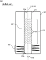
FIGS. 8A and 8B are schematic illustrations of an apparatus for continuously filtering contaminants from a viscous fluid including a stationary filter element according to some embodiments of the present invention;
FIGS. 8C and 8D are schematic views of an apparatus for continuous filtration of contaminants from a viscous fluid, the apparatus including a stationary filter element and further including one or more longitudinal fins, according to some embodiments of the invention;
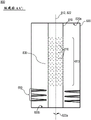
FIG. 8E is a schematic view of an apparatus for continuously filtering contaminants from a viscous fluid, the apparatus including a stationary filter element and further including one or more sections of helically wound fins, according to some embodiments of the invention;
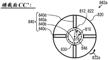
FIGS. 8F and 8G are schematic views of an apparatus for continuous filtration of contaminants from a viscous fluid, the apparatus including a fixed filter element and further including one or more sets of one or more sections of longitudinal fins and helically wound fins, according to some embodiments of the invention;
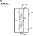
FIG. 8H is an enlarged view of the cross-section of FIG. 8G emphasizing the nature of the flow of contaminated viscous fluid in the gaps formed between the fins and the perforated surface in accordance with an embodiment of the invention; and
FIG. 9 is a schematic illustration of a method of continuously filtering contaminants from a viscous fluid.
It will be appreciated that for simplicity and clarity of illustration, elements shown in the figures have not necessarily been drawn to scale. For example, the dimensions of some of the elements may be exaggerated relative to other elements for clarity. Further, where considered appropriate, reference numerals may be repeated among the figures to indicate corresponding or analogous elements.
Detailed Description
In the following description, various aspects of the invention are described. For purposes of explanation, specific configurations and details are set forth in order to provide a thorough understanding of the present invention. However, it will also be apparent to one skilled in the art that the present invention may be practiced without the specific details presented herein. In addition, well-known features may have been omitted or simplified in order not to obscure the present invention. With specific reference to the drawings, it is stressed that the particulars shown are by way of example and for purposes of illustrative discussion of the present invention only, and are presented in the cause of providing what is believed to be the most useful and readily understood description of the principles and conceptual aspects of the invention. In this regard, no attempt is made to show structural details of the present invention in more detail than is necessary for a fundamental understanding of the present invention, the description taken with the drawings making apparent to those skilled in the art how the several forms of the present invention may be embodied in practice.
Before explaining at least one embodiment of the invention in detail, it is to be understood that the invention is not limited in its application to the details of construction and the arrangement of the components set forth in the following description or illustrated in the drawings. The invention is applicable to other embodiments and combinations of embodiments disclosed that may be practiced or carried out in various ways. Also, it is to be understood that the phraseology and terminology employed herein is for the purpose of description and should not be regarded as limiting.
Reference is now made to fig. 1A, 1B, 1C, 1D, and 1E, which are schematic illustrations of an apparatus 100 for continuous filtration of contaminants from viscous fluids, according to some embodiments of the present invention.
Fig. 1A and 1C show perspective views of the device 100 and the device 100', respectively. Fig. 1B shows a perspective view of the device 100, wherein the portion of the first cylindrical body 110 hidden by the second cylindrical body 120 is depicted by dashed lines. Fig. 1D and 1E show longitudinal section AA 'and transverse section BB', respectively, of device 100, where section AA 'and section BB' are defined in fig. 1A.
The device 100 may include a first cylindrical body 110 having a first longitudinal central axis 112 and a second cylindrical body 120 having a second longitudinal central axis 122. The first cylindrical body 110 and the second cylindrical body 120 may overlap such that the first longitudinal center axis 112 coincides with the second longitudinal center axis 122 and an annular gap 130 is formed between the first cylindrical body 110 and the second cylindrical body 120 (e.g., as shown in fig. 1A, 1B, 1C, 1D, and 1E).
In various embodiments, the first cylindrical body 110 may be disposed within the second cylindrical body 120 (e.g., as shown in fig. 1A, 1B, 1D, and 1E), or the second cylindrical body 120 may be disposed within the first cylindrical body 110 (e.g., as shown in fig. 1C).
The annular gap 130 between the first cylindrical body 110 and the second cylindrical body 120 may be adapted to receive a viscous fluid. For example, the viscous fluid may be a melt of a polymeric material. The melt of the polymeric material may, for example, include a variety of contaminants. For example, the contaminants may include hard solid particles of minerals, metals, fibers, and the like. In another example, the contaminants may include soft semi-solid particles of elastomers, foreign polymers with melting points higher than that of the viscous fluid, and the like.
The first cylindrical body 110 may be rotatably supported and adapted to rotate about a first longitudinal center axis 112 and relative to the second cylindrical body 120 (e.g., as indicated by arrow 112a in fig. 1A, 1B, 1C, 1D, and 1E).
The first cylindrical body 110 can include a plurality of apertures 116 disposed along at least a portion of a circumference of the first cylindrical body 110. The aperture 116 may be disposed along at least one longitudinal filter section 113 of the first cylindrical body 110 (e.g., in a direction along the first longitudinal center axis 112). For example, fig. 1B and 1C show enlarged portions 110a, 110B, respectively, of the circumference of the first cylindrical body 110 with the aperture 116.
In various embodiments, the shape and/or size of the orifices 116 and/or the distance between the orifices 116 and/or the topology of the position of the orifices 116 on the first cylindrical body 110 may be predetermined to enable a desired flow of the viscous fluid while preventing contaminants from passing therethrough. In some embodiments, the aperture 116 may have a circular shape.
In some embodiments, the aperture 116 may taper in a radial direction such that an opening 116a of the aperture 116 on the inner surface 111a of the first cylindrical body 110 may be larger than an opening 116b of the aperture 116 on the outer surface 111b of the first cylindrical body 110.
Reference is now made to fig. 1F and 1G, which are schematic illustrations of more detailed aspects of an apparatus 100 for continuous filtration of contaminants from viscous fluids, according to some embodiments of the present invention, and which further illustrate the operation of the apparatus 100.
Fig. 1F and 1G show longitudinal section AA 'and transverse section BB', respectively, of device 100, where section AA 'and section BB' are defined in fig. 1A.
Reference is also made to fig. 1H, which is a partial schematic illustration of the relative velocity component of a viscous fluid relative to the orifice 116 on the first cylindrical body 110 of the apparatus 100 for continuous filtration of contaminants from a viscous fluid, in accordance with an embodiment of the present invention.
According to some embodiments, the apparatus 100 may include a housing 140, a rotating assembly 150, and a controller 160.
The housing 140 may be adapted to accommodate the first cylindrical body 110 and the second cylindrical body 120, and the first cylindrical body 110 and the second cylindrical body 120 may be adapted to be mounted within the housing 140. The rotation assembly 150 may comprise at least a rotation motor coupled to the first cylindrical body 110 and adapted to rotate the first cylindrical body 110. The controller 160 may be in communication with the rotation assembly 150 and may be configured to control rotation of the first cylindrical body 110 by the rotation assembly 150.
According to some embodiments, a viscous fluid 90 with contaminants (e.g., a melt of a polymer material with contaminants) may be introduced into the annular gap 130 between the first cylindrical body 110 and the second cylindrical body 120. For example, the second cylindrical body 120 can include one or more inlet openings 124 at the first end 120a thereof, wherein the inlet opening(s) 124 can be in fluid communication with the annular gap 130, and can be adapted to allow introduction of the viscous fluid with contaminants 90 into the annular gap 130 (e.g., as shown in fig. 1F).
The continuous introduction of the contaminated viscous fluid 90 into the annular gap 130 may drive the contaminated viscous fluid 90 along the annular gap 130 in a longitudinal direction 132 extending between the first end 130a and the second end 130b of the annular gap 130, thereby creating a longitudinal flow 132a of viscous fluid.
The pressure generated within the annular gap 130 (e.g., at least due to the continuous introduction of the viscous fluid with contaminants 90 therein at a desired flow rate and introduction pressure) may drive the viscous fluid with contaminants 90 toward the perforated surface in the radial direction 134 while maintaining a substantially laminar tangential flow of the viscous contaminated fluid adjacent the perforated surface, thereby generating a radial flow 134a of the viscous fluid (e.g., in addition to the longitudinal flow 132a thereof). Thus, the pressure within the annular gap 130 may force the viscous fluid through the orifices 116 on the circumference of the first cylindrical body 110. The orifices 116 may prevent contaminants from passing therethrough, thereby filtering contaminants from the viscous fluid and retaining the contaminants within the annular gap 130. The clean viscous fluid 92 (e.g., free of contaminants or substantially free of contaminants) can be controllably removed from, for example, the second end 110b of the first cylindrical body 110 using a clean viscous fluid removal device 170.
The first cylindrical body 110 is continuously rotatable about its first longitudinal central axis 112 by the rotating assembly 150, thereby generating a laminar tangential drag flow 136a of the viscous fluid within the annular gap 130 in its tangential direction 136 (e.g., in addition to its longitudinal and radial flows). A tangential velocity gradient is created between the rotating first cylindrical body 110 and the stationary second cylindrical body 120. The contaminant particles in the layers away from the surface of the rotating first cylindrical body 110 slowly move (drag) at a slower tangential rate than the surface of the rotating first cylindrical body 110, resulting in a self-cleaning tangential relative motion 136b around the surface of the rotating first cylindrical body 110 in which the contaminant particles move tangentially around the outlet 120b (e.g., in the tangential direction 136) and longitudinally down towards the outlet 120b (e.g., in the longitudinal direction 132) and a motion towards the surface of the first cylindrical body 110 (e.g., in the radial direction 134). Contaminant particles having a size larger than the apertures 116 on the surface of the first cylindrical body 110 may continue their rotational movement even when contacting the surface of the rotating first cylindrical body 110, as long as the rotational speed of the first cylindrical body 110 is maintained and/or a desired shear rate (e.g., as described below) near the surface of the first cylindrical body 110 is maintained. It will be noted that, according to embodiments of the present invention, the flow of viscous fluid in a radial direction is maintained towards and through the perforated surface while the remaining fluid that does not pass through the perforated surface maintains a substantially laminar tangential flow, e.g., as depicted by arrows 136a in fig. 1G and 1H.
Typical viscosities of plastic melts range from a minimum of 0.1 pa.s (at a shear rate of 1001/s at melt processing temperatures) to orders of magnitude higher (up to 10,000 pa.s). It is known in the art that at such high viscosities, viscous forces dominate, while inertial forces (gravity or centrifugal forces) are relatively negligible. It is known that the ratio of inertial to viscous forces is the reynolds number (Re), where flow at low Re is characterized by a flow regime of smooth laminar flow, while at Re above about 2900, flow comprises turbulent flow. In the field of polymer melt processing, the flow is a smooth, swirl-free, laminar flow due to the high viscosity. In embodiments of the invention, the range of reynolds numbers maintains Re <1, i.e. in a stable laminar flow range.
Contaminant particles having a size larger than the apertures 116 on the surface of the first cylindrical body 110 may continue their rotational movement even when contacting the surface of the rotating first cylindrical body 110, as long as the rotational speed of the first cylindrical body 110 is maintained and/or the desired shear rate near the surface of the first cylindrical body 110 is maintained (e.g., as described below).
The rotational speed of the first cylindrical body 110 and the resulting tangential drag flow 136a and/or self-cleaning tangential relative motion 136b may be determined to substantially minimize the adherence of contaminants to the first cylindrical body 110 and to substantially minimize the clogging of the apertures 116 by contaminants (e.g., due to at least the self-cleaning tangential relative motion 136b), thereby creating a self-cleaning/cleaning effect. In some embodiments, the self-purging tangential relative motion 136b may be generated along the entire filter section 113 of the first cylindrical body 110 with the aperture 116. In this way, the self-cleaning/purging of the first cylindrical body 110 is applied simultaneously over the entire filter section 113.
The self-cleaning/clearing effect may result from the shear rate of the viscous fluid near the surface of the first cylindrical body 110, wherein, in some embodiments, the shear rate may be determined by at least the rotational speed of the first cylindrical body 110 and the size of the annular gap 130. For example, an average shear rate of at least 501/s (e.g., 100-5001/s) in the annular gap 130 may provide a self-cleaning/scavenging effect.
In general, the rotational speed of the first cylindrical body 110 may be controlled to ensure that the tangential velocity of the viscous fluid near the surface of the first cylindrical body 110 (e.g., due to the tangential drag flow 136a) is significantly higher than the average radial velocity of the viscous fluid (e.g., due to the radial flow 134 a). In some embodiments, the rotational speed may be controlled to provide a ratio of the maximum tangential velocity to the average radial velocity of at least 50 (e.g., at least 100-.
The contaminated viscous fluid 90 flowing within the annular gap 130 (e.g., due to continuous introduction of the contaminated viscous fluid 90 into the annular gap 130) may flow toward the outlet of the apparatus within the annular gap 130 at the second end 130b thereof. The controlled removal of the viscous fluid with contaminants 90 at the second end 130b of the annular gap 130 can help create pressure within the annular gap 130, and thus can help facilitate radial flow of the viscous fluid through the orifices 116 (e.g., in the direction 134) and filtration thereof from the viscous fluid with contaminants. The contaminant-laden viscous fluid 90 accumulated within the annular gap 130 at its second end 130b may be controllably removed (e.g., preferably continuously, or periodically or at a predetermined point in time) from the annular gap 130 using an unfiltered viscous fluid removal device 172 coupled to, for example, the second end 120b of the second cylindrical body 120.
According to some embodiments, the apparatus 100 may include a cooling unit 180 (e.g., as shown in fig. 1F). The cooling unit 180 may be adapted to cool the apparatus 100.
According to some embodiments, the disclosed apparatus (e.g., such as apparatus 100 described above with respect to fig. 1A, 1B, 1C, 1D, 1E, 1F, 1G, and 1H) may allow continuous filtration of viscous fluids (e.g., high viscosity fluids, such as melts of polymeric materials) while performing continuous self-cleaning of the apparatus. The self-cleaning of the device may be achieved by: the filter element (e.g., first cylindrical body 110) thereof is caused to rotate at a controlled rotational speed to generate a tangentially dragged flow (e.g., tangentially dragged flow 136a) of viscous fluid within an annular gap (e.g., annular gap 130 between first cylindrical body 110 and second cylindrical body 120) containing viscous fluid between the filter element and the stationary element and/or a self-cleaning tangential relative motion (e.g., self-cleaning tangential relative motion 136b) of viscous fluid within the annular gap immediately adjacent the filter element. The rotational speed of the filter element and the size of the annular gap may be determined to ensure that the rate of tangential drag flow (e.g., due to rotation of the filter element) is at least 50 times (e.g., at least 100 and 3000 times) the average rate of radial flow of the viscous fluid within the annular gap (e.g., due to pressure within the annular gap) and that the average shear rate within the annular gap is at least 501/s. In this manner, the resulting tangential drag flow and/or resulting self-cleaning tangential relative motion adjacent the filter element may substantially minimize the attachment of contaminants to the filter element and substantially minimize the clogging of the apertures (e.g., aperture 116) of the filter element, thereby creating a self-cleaning/cleaning effect of the filter element/apparatus. Accordingly, the disclosed apparatus may eliminate or significantly reduce the need for a cleaning procedure for the filter element (e.g., due to its self-cleaning/clearing), and thus may overcome the disadvantages of current filter apparatuses that typically apply a metal blade to the filter element, or a backflow of filtered viscous fluid to the filter element when the filter being cleaned is not in the filtering mode.
Reference is now made to fig. 2A, 2B, and 2C, which are schematic illustrations of an apparatus 200 for continuously filtering contaminants from a viscous fluid and including a first cylindrical body 210 with a plurality of slots 216, according to some embodiments of the present invention.
Fig. 2A shows a perspective view of the device 200. Fig. 2B and 2C show longitudinal section AA 'and transverse section BB', respectively, of device 200, where section AA 'and section BB' are defined in fig. 2A.
According to some embodiments, the apparatus 200 may include a first cylindrical body 210 having a first longitudinal central axis 212 and a second cylindrical body 220 having a second longitudinal central axis 222. The first cylindrical body 210 and the second cylindrical body 220 may overlap such that the first longitudinal center axis 212 coincides with the second longitudinal center axis 222 and an annular gap 230 is formed between the first cylindrical body 210 and the second cylindrical body 220.
The first cylindrical body 210 may be rotatably supported and adapted to rotate about a first longitudinal center axis 212 and relative to the second cylindrical body 220 (e.g., as indicated by arrow 212A in fig. 2A, 2B, and 2C). For example, the apparatus 200, the first cylindrical body 210, and the second cylindrical body 220 may be similar to the apparatus 100, the first cylindrical body 110, and the second cylindrical body 120 described above with respect to fig. 1A, 1B, 1C, 1D, 1E, 1F, 1G, and 1H, respectively.
According to some embodiments, the first cylindrical body 210 may include a plurality of slots 216 along a circumference of the first cylindrical body 210. The slot 216 may be similar to the aperture 116 described above with respect to fig. 1A, 1B, 1C, 1D, 1E, 1F, 1G, and 1H. The slot 216 may be disposed along at least one longitudinal filter section 218 (e.g., in a direction along the first longitudinal center axis 122) of the first cylindrical body 210 (e.g., as shown in fig. 2B). Each of the slots 216 may have a long dimension 216a and a short dimension 216b (e.g., as shown in fig. 2A). In some embodiments, the slots 216 may be aligned (or substantially aligned) along their long dimension 216a with the first longitudinal central axis 212 of the first cylindrical body 210 (e.g., as shown in fig. 2A).
The annular gap 230 may be adapted to receive the viscous fluid 90 with contaminants. At least some of the contaminants may have an elongated shape (e.g., elongated contaminants 94 shown in fig. 2C). The first cylindrical body 210 may be continuously rotated about its first longitudinal central axis 212 at a controlled rotational speed. The rotational speed of the first cylindrical body 210 may be controlled to provide a tangential velocity of a tangential drag flow of the viscous fluid near the surface of the first cylindrical body 210 (e.g., due to rotation of the first cylindrical body 210) that is at least 3 times an average longitudinal velocity of a longitudinal flow of the viscous fluid (e.g., in the longitudinal direction 232 along the annular gap 232). For example, the tangentially dragged flow and the longitudinal flow may be similar to the tangentially dragged flow 136a and the longitudinal flow 132a, respectively, described above with respect to fig. 1F, 1G, and 1H. In some embodiments, the rotational speed of at least the first cylindrical body 210 and the size of the annular gap 230 may result in a high shear rate of the viscous fluid near the surface of the first cylindrical body 210 (e.g., an average shear rate in the annular gap 130 of at least 501/s, such as 100-.
Such predominantly tangential drag flow and/or such high shear rate near the surface of the first cylindrical body 210 may cause the elongated contaminant 94 to align with the slot 216 substantially along a tangential direction within the annular gap 230 and substantially perpendicular to the first longitudinal central axis 212 of the first cylindrical body 210 (e.g., as shown in fig. 2C). In this manner, the passage of elongated contaminants (and/or the passage of soft elastomer contaminants stretched/elongated due to the high shear rate generated by the rotation of first cylindrical body 110) through slots 216 may be significantly minimized, which may enhance the self-cleaning of device 200. Moreover, such predominantly tangential drag flow may provide a longer path for the contaminated viscous fluid within the annular gap 230 and thus produce more efficient depletion of the clean viscous fluid from the contaminated viscous fluid.
In some embodiments, the longitudinal filter section 218 including the slot 216 may be disposed a predetermined distance 218a downstream of the first end 210a of the first cylindrical body 210 at which the viscous fluid 90 is introduced into the annular gap 230 (e.g., as shown in fig. 2B). The distance 218a may be predetermined based on a parameter (e.g., viscosity) of the viscous fluid 90 and the rotational speed of the first cylindrical body 210 to provide a sufficient distance to align the elongate contaminant 94 with the tangential drag flow before reaching the longitudinal filter section 218.
In some embodiments, the slots 216 may be aligned (or substantially aligned) with the actual velocity vector of the viscous fluid flow along their long dimension 216 a. The velocity vector may be determined based on a maximum tangential velocity of a tangentially dragged flow of the viscous fluid, a maximum longitudinal velocity of a longitudinal flow, and a maximum radial velocity of a radial flow.
Reference is now made to fig. 2D, which is a schematic illustration of an apparatus 200 for continuously filtering contaminants from a viscous fluid and including a first cylindrical body 210 with a plurality of flutes 219, according to some embodiments of the invention.
Fig. 2D shows a perspective view of the device 200 and an enlarged portion 210a of the circumference of the first cylindrical body 210 with the slot 216 and the groove 219.
According to some embodiments, the first cylindrical body 210 may include a plurality of grooves 219. The groove 219 may be provided on a surface of the first cylindrical body 210 facing the annular gap 230. In some embodiments, the depth of the groove 219 may be less than the short dimension 126b of the slot 216. In some embodiments, the groove 219 can be perpendicular (or substantially perpendicular) to the slot 216. In some embodiments, at least one of the grooves 219 may span at least one of the slots 216.
In general, the number, shape, location, and/or amount of recessing of the grooves 219 may be predetermined to provide a desired measure (measure) of roughness to the surface of the first cylindrical body 210. The desired measure of roughness may be selected to further minimize adhesion of contaminants to the first cylindrical body 210 and to minimize clogging of the slot 216 by contaminants, which may enhance the self-cleaning of the apparatus 200.
Note that the groove may be applied to the surface of the first cylindrical body having an aperture of any shape other than slot 216. For example, the first annular body 110 of the apparatus 100 (e.g., as described above with respect to fig. 1A, 1B, 1C, 1D, 1E, 1F, 1G, and 1H) may also include a groove, which may be similar to the groove 219.
Reference is now made to fig. 3A and 3B, which are schematic illustrations of various configurations of an apparatus 300 for continuous filtration of contaminants from viscous fluids and including at least one tapered cylindrical body, in accordance with some embodiments of the present invention.
Fig. 3A and 3B illustrate a longitudinal cross-section AA 'of the device 300 (e.g., similar to longitudinal cross-section AA' defined in fig. 1A).
According to some embodiments, the apparatus 300 may include a first cylindrical body 310 having a first longitudinal central axis 312 and a second cylindrical body 320 having a second longitudinal central axis 322. The first cylindrical body 310 and the second cylindrical body 320 may overlap such that the first longitudinal center axis 312 coincides with the second longitudinal center axis 322 and an annular gap 330 is formed between the first cylindrical body 310 and the second cylindrical body 320. For example, the apparatus 300, the first cylindrical body 310, the second cylindrical body 320, and the annular gap 330 may be similar to the apparatus 100, the first cylindrical body 110, and the second cylindrical body 120 described above with respect to fig. 1A, 1B, 1C, 1D, 1E, 1F, 1G, and 1H, respectively.
The first cylindrical body 310 may include a plurality of apertures 316. For example, the aperture 316 may be similar to the aperture 116 and/or slot 216 described above with respect to fig. 1A, 1B, 1C, 1D, 1E, 1F, 1G, and 1H, and 2A, 2B, 2C, and 2D, respectively.
The first cylindrical body 310 may be rotatably supported and adapted to rotate about a first longitudinal center axis 312 and relative to the second cylindrical body 320 (e.g., as indicated by arrow 312a in fig. 3A and 3B). The annular gap 330 between the first cylindrical body 310 and the second cylindrical body 320 may be adapted to receive a viscous fluid (e.g., a melt of a polymer material with contaminants).
In some embodiments, the first cylindrical body 310 may be tapered along its first longitudinal central axis 312. For example, the first cylindrical body 310 may have a smaller dimension at its first end 310a than at its second end 310b such that the gap 330 decreases along the first longitudinal center axis 312 (e.g., as shown in fig. 3A).
In some embodiments, the second cylindrical body 320 may be tapered along its second longitudinal central axis 322. For example, the second cylindrical body 320 may have a smaller dimension at its first end 320a than its second end 320B such that the gap 330 decreases along the second longitudinal central axis 322 (e.g., as shown in fig. 3B).
In some embodiments, both the first cylindrical body 310 and the second annular body 320 may be tapered along their respective longitudinal central axes such that the gap 330 decreases along their respective longitudinal central axes.
In general, a measure of the taper of the first cylindrical body 310 and/or the second cylindrical body 320 may be predetermined to provide the tapered annular gap 330. The taper of the annular gap 330 may be determined to compensate for the pressure loss of the viscous fluid 90 within the annular gap 330 due to the egress of the viscous fluid through the orifice 316 in the first cylindrical body 310.
Reference is now made to fig. 4A, 4B, and 4C and 4D, which are schematic illustrations of an apparatus 400 and an apparatus 400' for continuous filtration of contaminants from viscous fluids, and including one or more longitudinal fins 440, respectively, according to some embodiments of the present invention.
Fig. 4A and 4B show a longitudinal cross-section AA 'and a transverse cross-section BB', respectively, of the device 400 (e.g., similar to the longitudinal cross-section AA 'and transverse cross-section BB' defined in fig. 1A). Fig. 4C and 4D show a longitudinal cross-section AA ' and a transverse cross-section BB ', respectively, of the device 400' (e.g., similar to the longitudinal cross-section AA ' and the transverse cross-section BB ' defined in fig. 1A).
According to some embodiments, the apparatus 400 may include a first cylindrical body 410 having a first longitudinal central axis 412 and a second cylindrical body 420 having a second longitudinal central axis 422. The first cylindrical body 410 and the second cylindrical body 420 may overlap such that the first longitudinal central axis coincides with the second longitudinal central axis 422 and an annular gap 430 is formed between the first cylindrical body 410 and the second cylindrical body 420. For example, the apparatus 400, the first cylindrical body 410, the second cylindrical body 420, and the annular gap 430 may be similar to the apparatus 100, the first cylindrical body 110, and the second cylindrical body 120 described above with respect to fig. 1A, 1B, 1C, 1D, 1E, 1F, 1G, and 1H, respectively.
The first cylindrical body 410 may be rotatably supported and adapted to rotate about a first longitudinal center axis 412 and relative to the second cylindrical body 420 (e.g., as indicated by arrow 412a in fig. 4A and 4B). An annular gap 430 between the first and second cylindrical bodies 410, 420 may be adapted to receive a viscous fluid (e.g., a melt of a polymer material with contaminants). In some embodiments, the first cylindrical body 410 may be disposed within the second cylindrical body 420 (e.g., as shown in fig. 4A and 4B), or the second cylindrical body 420 may be disposed within the first cylindrical body 410 (e.g., as shown in fig. 4C and 4D).
First cylindrical body 410 may include a plurality of apertures 416 disposed along at least a portion of a circumference of first cylindrical body 410. The aperture 416 may be disposed along at least one longitudinal filter segment 413 of the first annular body 410. For example, aperture 416 may be similar to aperture 116 and/or slot 216 described above with respect to fig. 1A, 1B, 1C, 1D, 1E, 1F, 1G, and 1H, and 2A, 2B, 2C, and 2D, respectively.
According to some embodiments, the second cylindrical body 420 may include one or more longitudinal fins 440. The longitudinal fin(s) 440 may protrude from the second cylindrical body 420 into the annular gap 430 and toward (or substantially toward) the first cylindrical body 410. The longitudinal fin(s) 440 may be aligned with the second longitudinal central axis 422 of the second cylindrical body 420 and/or may extend in a longitudinal direction thereof along at least a portion of the length of the second cylindrical body 420.
The longitudinal fin(s) 440 may protrude from the second cylindrical body 420 to provide a space 448 having an increased shear rate between the end of the longitudinal fin(s) 440 and the first cylindrical body 410. In this manner, the shear rate of the viscous fluid in the space 448 between the ends of the longitudinal fin(s) 440 and the first cylindrical body 410 having an increased shear rate may be increased (e.g., as compared to an embodiment without the longitudinal fin(s) 410), which may further facilitate self-cleaning/clearing of the first cylindrical body 410.
In general, the number of longitudinal fin(s) 440 and the spaces 448 having increased shear rates can be determined to provide increased shear rates between the ends of the longitudinal fin(s) 440 and the first cylindrical body 410 without reducing (or with minimal reduction) the open cross-section of the axial flow of viscous fluid through the apparatus 400 (e.g., as compared to embodiments without the longitudinal fin(s) 440). The increased shear rate in the spaces 448 having an increased shear rate may contribute to the self-cleaning effect of the apparatus 400.
In some embodiments, the device 400 may include a housing 402. The housing 402 may be adapted to house a first cylindrical body 410 and a second cylindrical body 420.
In some embodiments, the apparatus 400 may include at least one inlet opening 404 through which the contaminated viscous fluid 90 may be pumped into the annular gap 430. In some embodiments, the apparatus 400 may include a contaminated viscous fluid removal device 406 (e.g., including one or more tubes, one or more pumps, etc.) for controllably removing the contaminated viscous fluid 90 from the annular gap 430. In some embodiments, the apparatus 400 may include a cleaning viscous fluid removal device 408 (e.g., including one or more tubes, one or more pumps, etc.) for controllably removing the cleaning viscous fluid 92 from the apparatus 400.
In some embodiments, the apparatus 400 may include a rotation assembly 450 for rotating the first cylindrical body 410. In some embodiments, the apparatus 400 may include a controller 460 for controlling at least one of: rotation of the first cylindrical body 410 by the rotation assembly 450, removal of the contaminated viscous fluid by the contaminated viscous fluid removal device 406, and removal of the clean viscous fluid 92 by the clean viscous fluid removal device 408.
The following description with respect to fig. 4C and 4D provides examples of the dimensions of the apparatus 400', the operating conditions of the apparatus 400', and the contaminated viscous fluid 90. Those skilled in the art will recognize that this example only describes certain embodiments within the scope of the present invention, and that other operating conditions with different viscous materials and various size ranges of the apparatus 400' may be designed and operated within the scope of the present invention.
For example, the second cylindrical body 420 may have a diameter of 220 mm. The second cylindrical body 420 may be disposed within the rotatable first cylindrical body, wherein the diameter of the first cylindrical body 410 may be, for example, 250 mm. The filter section 413 on the first cylindrical body 410 may for example have a length of 400 mm.
The longitudinal fin(s) 440 may protrude from the second cylindrical body 420 such that the space 448 between the end of the longitudinal fin(s) 440 and the first cylindrical body 410 having an increased shear rate may be, for example, 2 mm.
The apertures 416 on the first cylindrical body 410 may be, for example, slots (e.g., similar to the slots 216 described above with respect to fig. 2A, 2B, 2C, and 2D), which may have a dimension of 60 x 400 μm, and may be aligned along their long dimension with the first longitudinal central axis 412 of the first cylindrical body 410. The number of apertures/slots 416 on first cylindrical body 410 may be, for example, about 1,240,000. The aperture/slot 416 may be radially tapered (e.g., as shown in fig. 4C). The width of opening 416a of aperture/slot 416 on outer surface 410a of first cylindrical body 410 may be, for example, 120 μm, and the width of opening 416b on inner surface 410b of first cylindrical body 410 may be, for example, 60 μm.
The contaminated viscous fluid 90 may for example be a mixture from post-consumer recycled polyethylene grades containing for example 2% of contaminants having solid particles with a size below for example 500 μm. The contaminated viscous fluid 90 may, for example, have a viscosity of 200 Pa · s at 170 ℃ and a shear rate of 1501/s. In some embodiments, the contaminated fluid will have a viscosity greater than or equal to 40 pa.s.
The contaminated viscous fluid 90 may be pumped into the annular gap 430 at a temperature of, for example, 170 ℃. The first cylindrical body 410 may rotate, for example, at 50 RPM. The contaminated viscous fluid 90 may be controllably pumped into the annular gap 430 at a flow rate of, for example, 1200 kg/hr, which may provide a pressure within the annular gap of, for example, 80-120 bar.
The temperature of the contaminated viscous fluid 90 may rise, for example, by 6-14 ℃ (e.g., due to energy dissipated in shearing the viscous material) as the viscous fluid 90 passes through the apparatus 400'.
It is noted that other sizes and operating conditions of the apparatus 400' and other contaminated viscous fluids 90 may also be used.
Reference is now made to fig. 5, which is a schematic illustration of an apparatus 500 for continuously filtering contaminants from a viscous fluid and including one or more sections of helically wound fins 540, according to some embodiments of the present invention.
Fig. 5 illustrates a longitudinal cross-section AA '(e.g., similar to longitudinal cross-section AA' defined in fig. 1A) of device 500.
According to some embodiments, the apparatus 500 may include a first cylindrical body 510 having a first longitudinal center axis 512 and a second cylindrical body 520 having a second longitudinal center axis 522. The first cylindrical body 510 and the second cylindrical body 520 may overlap such that the first longitudinal center axis coincides with the second longitudinal center axis 522 and an annular gap 530 is formed between the first cylindrical body 510 and the second cylindrical body 520. For example, the apparatus 500, the first cylindrical body 510, the second cylindrical body 520, and the annular gap 530 may be similar to the apparatus 100, the first cylindrical body 110, and the second cylindrical body 120 described above with respect to fig. 1A, 1B, 1C, 1D, 1E, 1F, 1G, and 1H, respectively.
The first cylindrical body 510 may be rotatably supported and adapted to rotate about a first longitudinal center axis 512 and relative to the second cylindrical body 520 (e.g., as indicated by arrow 512a in fig. 5). An annular gap 530 between the first cylindrical body 510 and the second cylindrical body 520 may be adapted to receive a viscous fluid (e.g., a melt of a polymer material with contaminants).
The first cylindrical body 510 may include a plurality of apertures 516 disposed along at least a portion of a circumference of the first cylindrical body 510. The apertures 516 may be disposed along at least one longitudinal filter section 513 of the first annular body 510. For example, apertures 516 may be similar to apertures 116 and/or slots 216 described above with respect to fig. 1A, 1B, 1C, 1D, 1E, 1F, 1G, and 1H, and 2A, 2B, and 2C, respectively.
According to some embodiments, the first annular body 510 may include at least one section of the helically coiled fin 540. The helically coiled fin 540 may be disposed along the first longitudinal center axis 512 of the first cylindrical body 510 and may protrude into the annular gap 530. The helically wound fin(s) 540 may be disposed downstream of the longitudinal filtering section(s) 513 (e.g., as shown in fig. 5).
The helically wound fin(s) 540 may generate additional suction (e.g., forward pumping) against the viscous fluid being introduced into the annular gap 530. In this manner, the coiled fin(s) 540 may provide a lower operating pressure range within the apparatus 500 (e.g., as compared to embodiments without the coiled fin(s) 540) and/or help adapt the apparatus 500 to existing extruders that are typically adapted to operate under certain pressure conditions.
Reference is now made to fig. 6A and 6B, which are schematic illustrations of an apparatus 600 for continuous filtration of contaminants from a viscous fluid and including one or more groups 640 of longitudinal fins 642 and one or more sections of helically wound fins 650, according to some embodiments of the invention.
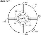
Fig. 6A and 6B illustrate a longitudinal cross-section AA ' (e.g., similar to longitudinal cross-section AA ' defined in fig. 1A) and a transverse cross-section CC ' (defined in fig. 6A), respectively, of device 600.
According to some embodiments, the apparatus 600 may include a first cylindrical body 610 having a first longitudinal central axis 612 and a second cylindrical body 620 having a second longitudinal central axis 622. The first cylindrical body 610 and the second cylindrical body 620 may overlap such that the first longitudinal center axis coincides with the second longitudinal center axis 622 and an annular gap 630 is formed between the first cylindrical body 610 and the second cylindrical body 620. For example, the apparatus 600, the first cylindrical body 610, the second cylindrical body 620, and the annular gap 630 may be similar to the apparatus 100, the first cylindrical body 110, and the second cylindrical body 120 described above with respect to fig. 1A, 1B, 1C, 1D, 1E, 1F, 1G, and 1H, respectively.
The first cylindrical body 610 may be rotatably supported and adapted to rotate about a first longitudinal center axis 612 and relative to the second cylindrical body 620 (e.g., as indicated by arrow 612a in fig. 5). An annular gap 630 between the first and second cylindrical bodies 610, 620 may be adapted to receive a viscous fluid (e.g., a melt of a polymer material with contaminants).
According to some embodiments, the first cylindrical body 610 may include one or more filter sections 613 along its first longitudinal central axis 612. For example, fig. 6A shows an apparatus 600 having two filter segments 613 (a first filter segment 613a and a second filter segment 613 b). Each of filter section(s) 613 may include a plurality of apertures 616 disposed on the circumference of first cylindrical body 610 in the respective filter section. For example, the apertures 616 may be similar to the apertures 116 and/or slots 216 described above with respect to fig. 1A, 1B, 1C, 1D, 1E, 1F, 1G, and 1H, and 2A, 2B, and 2C, respectively.
According to some embodiments, the second cylindrical body 620 may include one or more groups 640 of longitudinal fins 642. Each of the sets 640 may include one or more longitudinal fins 642. Each of the longitudinal fins 642 may be similar to, for example, the longitudinal fins 440 described above with respect to fig. 4A and 4B.
In some embodiments, each of the sets 640 may be disposed on the second annular body 620 at a location corresponding to a location of one of the filter section(s) 613 on the first cylindrical body 610. Longitudinal fin(s) 642 of each of the sets 640 may protrude from the second cylindrical body 620 into the annular gap 630 and toward (or substantially toward) the respective filter section 613 on the first cylindrical body 610. The longitudinal fin(s) 642 of each set 640 may be aligned with the second longitudinal central axis 622 of the second cylindrical body 620 and/or may extend along at least a portion of the length of the respective filter segment 613.
For example, fig. 6A shows a device 600 in which the second cylindrical body 620 includes two sets 640 (a first set 640a and a second set 640b) of longitudinal fins 642. However, in this example, the first group 640a is disposed at a location along the second cylindrical body 620 corresponding to the location of the first filter section 613a on the first cylindrical body 610, and the second group 640b is disposed at a location along the second cylindrical body 620 corresponding to the location of the second filter section 613b on the first cylindrical body 610. However, in this example, each of the first and second groups 640a, 640B includes four longitudinal fins 642 — a first longitudinal fin 642a, a second longitudinal fin 642B, a third longitudinal fin 642c, and a fourth longitudinal fin 642d (e.g., as shown in fig. 6B).
In some embodiments, the longitudinal fin(s) 642 of each group 640 may protrude from the second cylindrical body 620 to provide a space 648 between the end of the longitudinal fin(s) 642 and the first cylindrical body 610 with an increased shear rate. In this manner, the shear rate of the viscous fluid in the space 648 with an increased shear rate between the ends of the longitudinal fin(s) 642 and the filter section 613 on the first cylindrical body 610 may be increased (e.g., as compared to embodiments without the longitudinal fin(s) 642), which may further aid in the self-cleaning of the apparatus 600 (e.g., as described above with respect to fig. 4A and 4B).
According to some embodiments, the first annular body 610 may include at least one section of helically wound fins 650. The helically wound fins 650 may be disposed along the first longitudinal center axis 612 of the first cylindrical body 610 and may protrude into the annular gap 630. The helical coil fin 650 may be similar to the helical coil fin 540 described above with respect to fig. 5, for example.
In various embodiments, first cylindrical body 610 may include one or more sections of helically coiled fin 650 downstream of at least one of filter section(s) 613 on first cylindrical body 610. For example, fig. 6A shows an apparatus 600 that includes a first section of helically wound fins 650a, a second section of helically wound fins 650b, and a third section of helically wound fins 650 c. However, in this example, a first section 650a of the helically wound fin is disposed downstream of the first filter section 613a, and a second section 650b of the helically wound fin is disposed downstream of the second filter section 613 b.
The helically wound fin(s) 650 may generate additional suction (e.g., forward pumping) against the viscous fluid being introduced into the annular gap 630. In this manner, the coiled fin(s) 650 may provide a lower operating pressure range within the apparatus 600 (e.g., as compared to embodiments without the coiled fin(s) 650) and/or help adapt the apparatus 600 to existing extruders typically adapted to operate under certain pressure conditions.
Reference is now made to fig. 7A and 7B, which are schematic illustrations of an apparatus 700 for continuously filtering contaminants from a viscous fluid and including a washing assembly 740, according to some embodiments of the invention.
Fig. 7A illustrates a longitudinal cross-section AA '(e.g., similar to longitudinal cross-section AA' defined in fig. 1A) in device 700. Fig. 7B shows a transverse cross-section DD' (defined in fig. 7A) of the device 700, respectively.
According to some embodiments, the apparatus 700 may include a first cylindrical body 710 having a first longitudinal central axis 712 and a second cylindrical body 720 having a second longitudinal central axis 722. The first cylindrical body 710 and the second cylindrical body 720 may overlap such that the first longitudinal center axis coincides with the second longitudinal center axis 722 and an annular gap 730 is formed between the first cylindrical body 710 and the second cylindrical body 720. For example, the apparatus 700, the first cylindrical body 710, the second cylindrical body 720, and the annular gap 730 may be similar to the apparatus 100, the first cylindrical body 110, and the second cylindrical body 120 described above with respect to fig. 1A, 1B, 1C, 1D, 1E, 1F, 1G, and 1H, respectively.
The first cylindrical body 710 may be rotatably supported and adapted to rotate about a first longitudinal center axis 712 and relative to the second cylindrical body 720 (e.g., as indicated by arrow 712a in fig. 7A and 7B). An annular gap 730 between the first cylindrical body 710 and the second cylindrical body 720 may be adapted to receive a viscous fluid (e.g., a melt of a polymer material with contaminants).
First cylindrical body 710 may include a plurality of apertures 716 disposed along at least a portion of a circumference of first cylindrical body 710. The apertures 713 may be disposed along at least one longitudinal filter segment 713 of the first annular body 710. For example, aperture 716 may be similar to aperture 116 and/or slot 216 described above with respect to fig. 1A, 1B, 1C, 1D, 1E, 1F, 1G, and 1H, and 2A, 2B, and 2C, respectively.
According to some embodiments, the apparatus 700 may include a washing assembly 740. The washing assembly 740 may include at least one washing sprayer 742. The wash injector(s) 742 may include a plurality of injector holes/slots 744.
In some embodiments, when the first cylindrical body 710 is disposed within the second cylindrical body 720, the wash injector(s) 742 may be disposed within the interior 714 of the first cylindrical body 710 such that the injector holes/slots 744 face the first cylindrical body 710 (e.g., as shown in fig. 7A and 7B). In some other embodiments, when the second cylindrical body 720 is disposed within the first cylindrical body 710, the wash injector(s) 742 may be disposed outside of the first cylindrical body 710 and adjacent (or substantially adjacent) to the first cylindrical body 710 and within a housing of the apparatus (e.g., such as the housing 140 described above with respect to fig. 1F and 1G). The wash injector(s) 742 may be sized to extend along at least a portion of the longitudinal filtering section 713 with the aperture 716 and/or along at least a portion of a circumference thereof.
The wash assembly 740 may include at least one wash pipe 746 in fluid communication with the at least one wash sprayer 742 and adapted to deliver a clean viscous fluid to the wash sprayer(s) 742. In some embodiments, the viscous fluid cleaned may be the same viscous fluid cleaned by the first annular body 710. The cleaning viscous fluid can be sprayed through the injector holes/slots 744 in the wash injector(s) 742 towards the rotating first cylindrical body 710, covering a portion of the orifice 716 and creating a backflow (e.g., in a radial direction of the cleaning viscous fluid in the respective portion of the orifice) at each point in time. The backflow of the cleaning viscous fluid created in the portion of its apertures may push contaminants contained in the viscous fluid within the annular gap 730 away from the first annular body 710, thereby enhancing the self-cleaning/purging effect of the apparatus 700.
In some embodiments, washing of the perforated surface may be achieved without utilizing backflow achieved in the orifices. The pressure of the fluid on the 'clean' side of the perforated surface may rise within a defined short period, e.g. such that the pressure on both sides of the perforated surface is substantially equal. For example, the cleaning viscous fluid can be injected through injector holes/slots 744 in the wash injector(s) 742 until the pressure on both sides of the perforated surface is substantially equalized, and then the flow of the cleaning viscous fluid can be controlled to maintain this condition for a desired period of time. During this time, the radial flow of the viscous fluid across the perforated surface is essentially completely stopped, while the tangential flow on the perforated surface continues on the side of the contaminated fluid. The shear forces created near the perforated surface can then hold contaminants that adhere to the perforated surface and cause them to drift with the flow, thereby washing the perforated surface without the use of backflow. In some embodiments, the pressure drop between the high pressure side (the side contaminated with fluid) and the low pressure side (the side cleaned with fluid) of the perforated surface may be reduced to reduce the pressure drop, thereby extending the self-cleaning effect of the perforated surface. In some embodiments, the rotational speed of the second cylindrical body may be increased for a short period of time at a given rotational speed acceleration, and then decelerated to a nominal rotational speed at a lower rate in order to momentarily increase the cleaning effect of the clogged contaminants from exiting the perforations due to the accelerated rotational speed.
In some embodiments, the first cylindrical body 710 may include a cleaning viscous fluid outlet 770 for controllably removing cleaning viscous fluid from the interior of the first cylindrical body 710. For example, the cleaning viscous fluid outlet 770 may be similar to the cleaning viscous fluid removal device 170 described above with respect to fig. 1F.
In some embodiments, the second cylindrical body 720 can include an unfiltered viscous fluid outlet 772 for controllably removing unfiltered viscous fluid with contaminants that accumulate within the annular gap 730. For example, the unfiltered viscous fluid outlet 772 can be similar to the unfiltered viscous fluid removal device 172 described above with respect to fig. 1F.
Reference is now made to fig. 8A and 8B, which are schematic illustrations of an apparatus 800 for continuously filtering contaminants from a viscous fluid including a stationary filter element, according to some embodiments of the present invention.
Fig. 8A and 8B show a longitudinal cross-section AA 'and a transverse cross-section BB', respectively, of the device 800 (e.g., similar to the longitudinal cross-section AA 'and transverse cross-section BB' defined in fig. 1A).
According to some embodiments, the apparatus 800 may include a first cylindrical body 810 having a first longitudinal central axis 812 and a second cylindrical body 820 having a second longitudinal central axis 822. The first cylindrical body 810 and the second cylindrical body 820 may overlap such that the first longitudinal center axis 812 coincides with the second longitudinal center axis 822 and an annular gap 830 is formed between the first cylindrical body 810 and the second cylindrical body 820. For example, the device 800, the first cylindrical body 810, the second cylindrical body 820, and the annular gap 830 may be similar to the device 100, the first cylindrical body 110, and the second cylindrical body 120 described above with respect to fig. 1A, 1B, 1C, 1D, 1E, 1F, 1G, and 1H, respectively.
The first cylindrical body 810 may include a plurality of apertures 816 disposed along at least a portion of a circumference of the first cylindrical body 810. The apertures 816 may be disposed along at least one longitudinal filtering section 813 of the first annular body 810. For example, apertures 816 may be similar to apertures 116 and/or slots 216 described above with respect to fig. 1A, 1B, 1C, 1D, 1E, 1F, 1G, and 1H, and 2A, 2B, 2C, and 2D, respectively.
The second cylindrical body 820 may be rotatably supported and adapted to rotate about a second longitudinal central axis 822 and relative to the first cylindrical body 810 (e.g., as indicated by arrow 822a in fig. 8A and 8B). An annular gap 830 between the first cylindrical body 810 and the second cylindrical body 820 may be adapted to receive a viscous fluid (e.g., a melt of a polymer material with contaminants).
The second cylindrical body 820 may be continuously rotated about its second longitudinal center axis 822, thereby creating a tangential drag flow of the viscous fluid within the annular gap 830 in a tangential direction thereof. Thus, a tangential velocity gradient may be created between the rotating second cylindrical body 820 and the fixed first cylindrical body 810. The contaminant particles in the layers away from the surface of the fixed first cylindrical body 810 may slowly move at some tangential velocity when the velocity of the fixed first cylindrical body 810 is zero, resulting in a self-cleaning tangential relative motion around the surface of the fixed first cylindrical body 810 in which the contaminant particles move tangentially around the outlet (e.g., in a tangential direction) and longitudinally down towards the outlet (e.g., in a longitudinal direction), as well as a motion towards the surface of the first cylindrical body 810 (e.g., in a radial direction), e.g., as described above with respect to fig. 1F and 1G. Contaminant particles having a size larger than the apertures 816 on the surface of the first cylindrical body 810 may continue their rotational movement even when contacting the surface of the fixed first cylindrical body 810, as long as the rotational speed of the second cylindrical body 820 and the shear rate near the first cylindrical body 810 are maintained.
The rotational speed of the second cylindrical body 820 and the resulting tangential drag flow within the annular gap 830 and/or the self-cleaning tangential relative motion adjacent the first cylindrical body 810 (e.g., similar to the tangential drag flow 136a and the self-cleaning tangential relative motion 136b, respectively, as described above with respect to fig. 1F, 1G, and 1H) may be adapted to substantially minimize the adherence of contaminants to the first cylindrical body 810 and to substantially minimize the clogging of the apertures 816 with contaminants (e.g., due to at least the self-cleaning tangential relative motion), thereby creating a self-cleaning/cleaning effect.
The self-cleaning/clearing effect may result from the shear rate of the viscous fluid near the surface of the first cylindrical body 810, wherein, in some embodiments, the shear rate may be dictated at least by the rotational speed of the second cylindrical body 820 and the size of the annular gap 830.
In general, the rotational speed of the second cylindrical body 820 may be controlled to ensure that the tangential velocity of the viscous fluid near the surface of the second cylindrical body 810 (e.g., due to tangential drag flow within the annular gap 830) is significantly higher than the average radial velocity of the viscous fluid due to radial flow within the annular gap 830 (e.g., similar to the radial flow 134a described above with respect to fig. 1F, 1G, and 1H).
In various embodiments, the first cylindrical body 810 may be disposed within the second cylindrical body 820 (e.g., as shown in fig. 8A and 8B), or the second cylindrical body 820 may be disposed within the first annular body 810 (e.g., as described above with respect to fig. 1C).
According to some embodiments, the apparatus 800 may include a rotation assembly including at least a rotation motor. A rotation motor may be coupled to the second cylindrical body 820 and adapted to rotate the second cylindrical body 820 at a controlled rotational speed. The device 800 may also include a controller in communication with the rotating assembly. The controller may be configured to control the rotation of the second cylindrical body 820 through the rotating assembly according to the controlled rotation speed. For example, the rotation assembly and controller may be similar to the rotation assembly 150 and controller 160, respectively, as described above with respect to fig. 1F.
Reference is now made to fig. 8C and 8D, which are schematic illustrations of an apparatus 800 for continuous filtration of contaminants from a viscous fluid, the apparatus including a stationary filter element and further including one or more longitudinal fins 840, according to some embodiments of the present invention.
Fig. 8C and 8D show longitudinal cross-section AA ' and transverse cross-section BB ', respectively, of device 800' (e.g., similar to longitudinal cross-section AA ' and transverse cross-section BB ' defined in fig. 1A).
According to some embodiments, the second cylindrical body 820 may include one or more longitudinal fins 840. For example, the longitudinal fin(s) 840 may be similar to the longitudinal fin(s) 440 described above with respect to fig. 4A and 4B.
The longitudinal fin(s) 840 may protrude from the second cylindrical body 820 into the annular gap 830 and toward (or substantially toward) the first cylindrical body 810. The longitudinal fin(s) 840 may be aligned with the second longitudinal central axis 822 of the second cylindrical body 820 and/or may extend in a longitudinal direction thereof along at least a portion of the length of the second cylindrical body 820.
The longitudinal fin(s) 840 may protrude from the second cylindrical body 820 to provide a space 848 having an increased shear rate between the end of the longitudinal fin(s) 840 and the first cylindrical body 810. In this manner, the shear rate of the viscous fluid in the space 848 with increased shear rate between the end of the longitudinal fin(s) 840 and the first cylindrical body 810 may be increased (e.g., as compared to an embodiment without the longitudinal fin(s) 840), which may further facilitate self-cleaning/clearing of the first cylindrical body 810.
Reference is now made to fig. 8E, which is a schematic illustration of an apparatus 800 for continuously filtering contaminants from a viscous fluid, including a stationary filter element and also including one or more sections of helically wound fins 850, according to some embodiments of the invention.
According to some embodiments, the second annular body 820 may include at least one section of helically coiled fins 850. The helically coiled fin 850 may be disposed along the second longitudinal center axis 822 of the second cylindrical body 820 and may protrude into the annular gap 830. A helically coiled fin 850 may be disposed downstream of the longitudinal filter section 813. The helical coiled fin 850 may be similar to the helical coiled fin 850 described above with respect to fig. 5, for example.
The coiled fin(s) 850 may create additional suction against the viscous fluid being introduced into the annular gap 830. In this manner, the coiled fin(s) 850 may set a lower operating pressure range within the apparatus 800 (e.g., as compared to embodiments without the coiled fin(s) 850) and/or help adapt the apparatus 800 to existing extruders that are typically adapted to operate under certain pressure conditions.
Reference is now made to fig. 8F and 8G, which are schematic illustrations of an apparatus 800 for continuous filtration of contaminants from a viscous fluid, including a fixed filter element, and further including one or more groups 842 of longitudinal fins 840 and one or more sections of helically wound fins 850, according to some embodiments of the invention.
Fig. 8F and 8G illustrate a longitudinal cross-section AA ' (e.g., similar to longitudinal cross-section AA ' defined in fig. 1A) and a transverse cross-section CC ' (defined in fig. 8A), respectively, of device 800.
According to some embodiments, the first annular body 810 may include one or more longitudinal filtering sections 813. For example, the first annular body 810 may include a first longitudinal filtering section 813a and a second longitudinal filtering section 813b (e.g., as shown in fig. 8F).
According to some embodiments, the second cylindrical body 820 may include one or more groups 842 of longitudinal fins 840. In some embodiments, each of the sets 840 may be disposed on the second annular body 820 at a location corresponding to a location of one of the filter section(s) 813 on the first cylindrical body 810. The longitudinal fin(s) 840 of each of the sets 842 may protrude from the second cylindrical body 820 into the annular gap 830 and toward (or substantially toward) the respective filter section 813 on the first cylindrical body 810. The longitudinal fin(s) 840 of each group 842 may be aligned with the second longitudinal central axis 822 of the second cylindrical body 822 and/or may extend along at least a portion of the length of the respective filter section 813.
For example, fig. 8F shows the device 800 wherein the second cylindrical body 820 includes two sets 842 of longitudinal fins 840 — a first set 842a and a second set 842 b. However, in this example, the first group 842a is disposed at a location along the second cylindrical body 820 that corresponds to the location of the first filter section 813a on the first cylindrical body 810, and the second group 842b is disposed at a location along the second cylindrical body 820 that corresponds to the location of the second filter section 813b on the first cylindrical body 810. However, in this example, each of the first and second groups 842a, 842b includes four longitudinal fins 840 — a first longitudinal fin 840a, a second longitudinal fin 840b, a third longitudinal fin 840c, and a fourth longitudinal fin 840d (e.g., as shown in fig. 8G).
According to some embodiments, the second annular body 820 may include at least one section of helically coiled fins 850 along the second longitudinal central axis 822 of the second cylindrical body 820.
In various embodiments, the second cylindrical body 810 may include one or more sections of the helically coiled fin 850 downstream of one or more of the filtering sections 813 on the first cylindrical body 810. For example, fig. 8F shows the device 800 including a first section of helically wound fins 850a and a second section of helically wound fins 850 b. However, in this example, the first section 850a of the helically coiled fin is disposed downstream of the first filter section 813a, and the second section 850b of the helically coiled fin is disposed downstream of the second filter section 813 b.
Referring now to FIG. 8H, which is an enlarged view of the cross-section of FIG. 8G, emphasizing the nature of the flow of contaminated viscous fluid in the gaps formed between the fins and the perforated surface according to an embodiment of the invention. The cylindrical body 820 may be rotatably supported and adapted to rotate about a second longitudinal center axis and relative to the first cylindrical body 810 (e.g., as indicated by arrow 822a in fig. 8A and 8B). An annular gap 830 between the first cylindrical body 810 and the second cylindrical body 820 may be adapted to receive a viscous fluid (e.g., a melt of a polymer material with contaminants). The second cylindrical body 820 may be continuously rotated about its second longitudinal central axis, thereby generating a tangential drag flow of the viscous fluid in the annular gap 830, in particular in its tangential direction, in the high shear zone, in a manner similar to that described with respect to fig. 8A-8G. Thus, a tangential velocity gradient may be created between the rotating end of the fins of the second cylindrical body 820 and the fixed first cylindrical body 810. According to some embodiments, the second cylindrical body 820 may include one or more fins 840 that extend from the second cylindrical body 820 toward the first cylindrical body 810 such that when the second cylindrical body 820 is rotated relative to the first cylindrical body 810, they define an annular gap 830 adjacent the end of the perforated surface of the first cylindrical body 810. Operational and structural parameters such as the viscosity of the molten contaminated fluid, the relative rotational speed of the second cylindrical body 820 with respect to the first cylindrical body 810, and the size of the gap 830 may be controlled and/or set to ensure that the conditions of the contaminated fluid flow in the gap 830 remain substantially laminar. The tangential, radial, and longitudinal components of the contaminated viscous fluid within the apparatus 800, and in particular the flow at the high shear zone (depicted by dashed circle 830') defined by the tips of the fins 840, are substantially the same as described by the radial, tangential, and longitudinal flows 134a, 136a, 132a of fig. 1G and 1H.
Reference is now made to fig. 9, which is a schematic illustration of a method 900 of continuously filtering contaminants from a viscous fluid, in accordance with some embodiments of the present invention. It will be apparent to those of ordinary skill in the art that the preferred operating conditions for embodiments of the present invention are those that maintain laminar (or substantially laminar) flow of the molten contaminating fluid in the gap between the fins and the first cylindrical body, such as gap 830 discussed above.
The method 900 may be implemented by an apparatus for continuously filtering contaminants from a viscous fluid, which apparatus may be configured to implement the method 900. For example, method 900 may be performed by apparatus 100 (e.g., as described above with respect to FIG. 1A, FIG. 1C, FIG. 1D, FIG. 1E, FIG. 1F, FIG. 1G, and FIG. 1H), apparatus 200 (e.g., as described above with respect to FIG. 2A, FIG. 2B, FIG. 2C, and FIG. 2D), apparatus 300 (e.g., as described above with respect to FIG. 3A and FIG. 3B), apparatus 400 (e.g., as described above with respect to FIG. 4A and FIG. 4B), device 500 (e.g., as described above with respect to fig. 5), device 600 (e.g., as described above with respect to fig. 6A and 6B), device 700 (e.g., as described above with respect to fig. 7A and 7B), and/or device 800 (e.g., as described above with respect to fig. 8A, 8B, 8C, 8D, 8E, 8F, and 8G). Note that method 900 is not limited to the flowchart and corresponding description illustrated in fig. 9. For example, in various embodiments, method 900 need not move through each illustrated block or stage, or in exactly the same order as illustrated and described.
According to some embodiments, method 900 may include pumping a contaminated viscous fluid between a non-perforated surface and a perforated surface disposed substantially parallel to each other with a defined gap, thereby forcing the contaminated viscous fluid to move in a longitudinal direction along the gap (stage 902).
For example, as described above with respect to fig. 1A-1I, 2A-2D, 3A-3B, 4A-4B, 5, 6A-6B, 7A-7B, and 8A-8G, the perforated surface may be shaped as a first cylindrical body having a first central longitudinal axis and the non-perforated surface may be shaped as a second cylindrical body having a second central longitudinal axis. Also, in this example, the second central longitudinal axis of the second cylindrical body may coincide with the first central longitudinal axis of the first cylindrical body to provide an annular gap therebetween. Also, in this example, the relative velocity may be directed tangential to the surface and perpendicular to the second central longitudinal axis of the second cylindrical body and the first central longitudinal axis of the first cylindrical body.
According to some embodiments, method 900 may include: the non-perforated surface and the perforated surface are moved relative to each other at a defined relative velocity, thereby forcing the contaminated viscous fluid to move in a direction substantially parallel to the relative velocity, thereby creating a shear rate in the contaminated viscous fluid proximate the perforated surface in a direction substantially parallel to the relative velocity (stage 904).
For example, the first cylindrical body may rotate relative to the second cylindrical body, or the second cylindrical body (e.g., as described above with respect to fig. 1A-1I, 2A-2D, 3A-3B, 4A-4B, 5, 6A-6B, 7A-7B) may rotate relative to the first cylindrical body (e.g., as described above with respect to fig. 8A-8G).
According to some embodiments, method 900 may include: pressure is provided to the contaminated viscous fluid, forcing the contaminated viscous fluid to move in a direction substantially perpendicular to the direction of the relative velocity (stage 906). For example as described above with respect to fig. 1F-1H.
According to some embodiments, method 900 may include: the relative velocity, pressure and average shear rate within the gap are adjusted such that a layer of contaminated viscous fluid adjacent the perforated surface is forced to flow through the perforation apertures of the perforated surface to the other side of the perforated surface while contaminants having a size larger than the size of the perforation apertures are forced to flow in a direction substantially parallel to the relative velocity (stage 908). For example as described above with respect to fig. 1F-1H. The perforation apertures may be, for example, elongated slots 216 as described above with respect to fig. 2A-2D.
According to some embodiments, method 900 may include: the relative velocity, pressure and average shear rate within the gap are set such that the average velocity of the contaminated viscous fluid in a direction substantially parallel to the relative velocity is at least 50 times (e.g., 100 times 3000 times) the average velocity of the contaminated viscous fluid towards the perforated surface (i.e., in the radial direction) and such that the average shear rate within the gap is at least 501/s (e.g., 100 times 5001/s) (stage 910). For example as described above with respect to fig. 1F-1H.
According to some embodiments, method 900 may include: while the filter is in the filtration mode, during actual filtration of the contaminated viscous fluid, contaminant particles accumulated on the perforated surface are removed by providing a pressurized jet of the fluid of the filtered viscous fluid from the other side of the perforated surface through the holes towards the side with the contaminated viscous fluid, or by setting the pressure drop on both sides of the perforated surface low, allowing drift forces to sweep away the captured contaminants (stage 912). For example, as described above with respect to fig. 7A-7B.
In the foregoing description, embodiments are examples or implementations of the invention. The various appearances of "one embodiment," "an embodiment," "some embodiments," or "some embodiments" are not necessarily all referring to the same embodiments. While various features of the invention may be described in the context of a single embodiment, these features may also be provided separately or in any suitable combination. Conversely, although the invention may be described in the context of separate embodiments for clarity, the invention may also be implemented in a single embodiment. Certain embodiments of the invention may include features from different embodiments disclosed above, and certain embodiments may combine elements from other embodiments disclosed above. The disclosure of elements of the present invention in the context of particular embodiments is not to be taken as limiting their use to only the particular embodiments. Further, it is to be understood that the present invention may be carried out or practiced in various ways, and that the present invention may be implemented in certain embodiments other than the embodiments outlined in the description above.
The invention is not limited to those figures or to the corresponding description. For example, the flow need not move through each illustrated box or state, or in exactly the same order as illustrated and described. Unless defined otherwise, the meanings of technical and scientific terms used herein are to be commonly understood by one of ordinary skill in the art to which this invention belongs. While the invention has been described with respect to a limited number of embodiments, these should not be construed as limitations on the scope of the invention, but rather as exemplifications of some of the preferred embodiments. Other possible variations, modifications, and applications are also within the scope of the invention. Accordingly, the scope of the invention should not be limited by what has been described so far, but by the appended claims and their legal equivalents.
Claims (23)
1. A method of continuously filtering contaminants from a contaminated viscous fluid, the method comprising:
pumping the contaminated viscous fluid between a non-perforated surface and a perforated surface, the non-perforated surface and the perforated surface being arranged substantially parallel to each other with a defined first gap, thereby forcing the contaminated viscous fluid to move in a longitudinal direction along the gap;
moving the non-perforated surface and the perforated surface relative to each other at a defined relative velocity, thereby forcing the contaminated viscous fluid to move in a direction substantially parallel to the relative velocity, thereby creating a shear rate in the contaminated viscous fluid in the vicinity of the perforated surface in a direction substantially parallel to the relative velocity;
wherein the perforated surface is shaped as a first cylindrical body having a first central longitudinal axis and the non-perforated surface is shaped as a second cylindrical body having a second central longitudinal axis coincident with the first longitudinal axis and the first and second cylindrical bodies overlap, and wherein the relative speed is a rotational speed and the first gap is an annular gap, and
wherein the second cylindrical body comprises one or more longitudinal fins protruding from the second cylindrical body into the first gap toward the perforated surface of the first cylindrical body, thereby forming a second gap between the distal tip of the fin and the perforated surface, the second gap being smaller than the first gap;
providing pressure to the contaminated viscous fluid, thereby forcing the contaminated viscous fluid to move in a direction substantially perpendicular to the direction of the relative velocity; and
adjusting the relative velocity, the pressure and the average shear rate at the second gap such that a layer of the contaminated viscous fluid adjacent the perforated surface is forced to flow through the perforated apertures of the perforated surface to the other side of the perforated surface, while contaminants having a size larger than the size of the perforated apertures are forced to flow in a direction substantially parallel to the relative velocity,
wherein the relative velocity is directed tangential to the surfaces of the first and second cylinders and perpendicular to the second central longitudinal axis of the second cylindrical body and the first central longitudinal axis of the first cylindrical body.
2. The method of claim 1, further comprising setting the relative velocity, the pressure, and the average shear rate within the second gap such that an average velocity of the contaminated viscous fluid in the second gap in a direction substantially parallel to the relative velocity is at least 50 times an average velocity of the contaminated viscous fluid toward a perforated surface, and such that the average shear rate within the second gap is at least 501/s.
3. The method of any one of claims 1-2, wherein the perforation apertures are slots each having a long dimension and a short dimension, and wherein the long dimension of the slots are substantially aligned substantially perpendicular to the relative velocity and parallel to the longitudinal axis of the first cylindrical body.
4. The method of claim 3, wherein the rotational speed of the second cylindrical body may be increased for a first period of time at a given rotational speed acceleration and then decelerated to a nominal rotational speed at a lower rate, thereby momentarily increasing the cleaning effect of contaminants off the perforated surface.
5. The method of any of claims 1 to 4, further comprising: removing contaminant particles accumulated on the perforated surface by increasing the pressure of the fluid of the filtered viscous fluid at the other side of the perforated surface during the actual filtration of the contaminated viscous fluid, preferably to substantially the same level as the pressure of the contaminated fluid at the side with the contaminated viscous fluid, and simultaneously maintaining the shear rate at the second gap by providing a pressurized jet of the filtered viscous fluid towards the side with the contaminated viscous fluid during the actual filtration of the contaminated viscous fluid.
6. The method of any of claims 2 or 3, wherein the perforated surface comprises a plurality of grooves, wherein a depth of the grooves is less than the short dimension of the slots, and wherein at least one of the grooves spans at least one of the slots.
7. The method of any of claims 1-6, wherein:
the perforated apertures are disposed along at least one longitudinal filter section along a circumference and length of the first cylindrical body.
8. The method of claim 7, wherein the first cylindrical body is disposed within the second cylindrical body.
9. The method of claim 7, wherein the second cylindrical body is disposed within the first cylindrical body.
10. The method of any of claims 7-9, wherein the annular gap is tapered along the common axis of rotation by at least one of the first cylindrical body being tapered along the first longitudinal central axis and the second cylindrical body being tapered along the second longitudinal central axis such that the annular gap is tapered along the first longitudinal center.
11. The method according to any one of claims 7 to 10, wherein one of the first or second cylindrical bodies comprises at least one section of helically coiled fins disposed along the respective longitudinal central axis and downstream of the at least one longitudinal filtering section, the helically coiled fins protruding into the annular gap.
12. An apparatus for continuously filtering contaminants from a viscous fluid, the apparatus comprising:
a first cylindrical body having a first longitudinal central axis and comprising at least one longitudinal filter section comprising a plurality of apertures along a circumference of the at least one longitudinal filter section; and
a second cylindrical body having a second longitudinal central axis coincident with the first longitudinal axis of the first cylindrical body;
wherein the first cylindrical body is adapted to overlap and rotate relative to the second cylindrical body such that an annular gap is formed between the first cylindrical body and the second cylindrical body, wherein the annular gap is adapted to receive the viscous fluid, and
wherein the second cylindrical body comprises one or more longitudinal fins protruding from the second cylindrical body into the annular gap toward the perforated surface of the first cylindrical body, thereby forming a second gap between the distal tip of the fin and the perforated surface, the second gap being smaller than the annular gap.
13. The apparatus of claim 12, further comprising:
a rotation assembly comprising at least a rotation motor coupled to one of the first and second cylindrical bodies and adapted to rotate said one of the first and second cylindrical bodies, respectively, at a controlled rotation speed; and
a controller in communication with the rotation assembly, the controller configured to control relative rotation between the first cylindrical body and the second cylindrical body via the rotation assembly according to the controlled rotational speed.
14. The apparatus of any of claims 12 or 13, wherein the first cylindrical body is disposed within the second cylindrical body.
15. The apparatus of any of claims 12-13, wherein the second cylindrical body is disposed within the first cylindrical body.
16. The apparatus of any one of claims 12-15, wherein the apertures are slots each having a long dimension and a short dimension, and wherein the long dimension of the slots is substantially aligned with the first longitudinal central axis of the first cylindrical body.
17. The apparatus of claims 12 to 16, further comprising one or more injection ports disposed on another side of the perforated surface, the one or more injection ports adapted to provide a pressurized jet of the fluid of the filtered viscous fluid from the other side of the perforated surface toward the side with the contaminated viscous fluid during actual filtering of the contaminated viscous fluid.
18. The apparatus of any one of claims 16 or 17, wherein the first cylindrical body further comprises a plurality of grooves along its circumference, wherein the grooves have a depth that is less than the short dimension of the slot.
19. The apparatus of claim 18, wherein at least one of the grooves spans at least one of the slots.
20. The apparatus of any one of claims 13 to 19, wherein the at least one longitudinal filter section is disposed a predetermined distance downstream from the first end of the first cylindrical body.
21. The apparatus of any of claims 13-20, wherein the annular gap tapers along the common axis of rotation by at least one of the first cylindrical body tapering along the first longitudinal central axis and the second cylindrical body tapering along the second longitudinal central axis such that the gap becomes smaller along the first longitudinal center.
22. The apparatus of any one of claims 13-21, wherein the first cylindrical body includes at least one section of a helically coiled fin disposed along the first longitudinal central axis, the helically coiled fin protruding into the annular gap.
23. The apparatus of any one of claims 13 to 22, further comprising a washing assembly comprising:
at least one wash injector comprising a plurality of spray holes/slots; and
a wash pipe in fluid communication with the at least one wash sprayer and adapted to deliver a clean viscous fluid to the at least one wash sprayer;
wherein the at least one wash injector is arranged and dimensioned so as to extend along at least a portion of the at least one longitudinal filter section of the first cylindrical body and is adapted to inject the cleaned viscous fluid from a cleaned viscous fluid side of the rotating first cylindrical body through its aperture towards the other side of the rotating first cylindrical body towards the rotating first cylindrical body.
Applications Claiming Priority (3)
| Application Number | Priority Date | Filing Date | Title |
|---|---|---|---|
| US201962905469P | 2019-09-25 | 2019-09-25 | |
| US62/905469 | 2019-09-25 | ||
| PCT/IL2020/051036 WO2021059268A1 (en) | 2019-09-25 | 2020-09-23 | Self cleaning device and method for continuous filtration of high viscosity fluids |
Publications (1)
| Publication Number | Publication Date |
|---|---|
| CN114728221A true CN114728221A (en) | 2022-07-08 |
Family
ID=75165619
Family Applications (1)
| Application Number | Title | Priority Date | Filing Date |
|---|---|---|---|
| CN202080081712.4A Pending CN114728221A (en) | 2019-09-25 | 2020-09-23 | Self-cleaning apparatus and method for continuous filtration of high viscosity fluids |
Country Status (11)
| Country | Link |
|---|---|
| US (1) | US20220331723A1 (en) |
| EP (1) | EP4034278A4 (en) |
| JP (1) | JP2022550352A (en) |
| KR (1) | KR20220069041A (en) |
| CN (1) | CN114728221A (en) |
| AU (1) | AU2020356606A1 (en) |
| BR (1) | BR112022005390A2 (en) |
| CA (1) | CA3152269A1 (en) |
| MX (1) | MX2022003489A (en) |
| WO (1) | WO2021059268A1 (en) |
| ZA (1) | ZA202202923B (en) |
Families Citing this family (1)
| Publication number | Priority date | Publication date | Assignee | Title |
|---|---|---|---|---|
| WO2022200830A1 (en) * | 2021-03-24 | 2022-09-29 | Gideon Pinto | Self cleaning device and method for continuous filtration of high viscosity fluids |
Family Cites Families (6)
| Publication number | Priority date | Publication date | Assignee | Title |
|---|---|---|---|---|
| AT403779B (en) * | 1996-01-22 | 1998-05-25 | Bacher Helmut | DEVICE FOR FILTERING PLASTIFIED THERMOPLASTIC PLASTICS AND FILTER ELEMENT FOR SUCH A DEVICE |
| US5944998A (en) * | 1998-04-21 | 1999-08-31 | Membrex, Inc. | Rotary filtration device with flow-through inner member |
| DE10229406A1 (en) * | 2002-06-29 | 2004-01-22 | Ettlinger Kunststoffmaschinen Gmbh | Device for the continuous filtering of material mixtures |
| CN102971059B (en) * | 2010-03-12 | 2016-03-16 | 螺旋水科技有限公司 | Filtering flow and particle aggregation apparatus and method |
| US8647516B2 (en) * | 2010-09-03 | 2014-02-11 | Johnny Leon LOVE | Filtration method with self-cleaning filter assembly |
| US9005369B2 (en) * | 2011-06-20 | 2015-04-14 | Whirlpool Corporation | Filter assembly for a dishwasher |
-
2020
- 2020-09-23 EP EP20868765.7A patent/EP4034278A4/en active Pending
- 2020-09-23 AU AU2020356606A patent/AU2020356606A1/en active Pending
- 2020-09-23 WO PCT/IL2020/051036 patent/WO2021059268A1/en unknown
- 2020-09-23 MX MX2022003489A patent/MX2022003489A/en unknown
- 2020-09-23 US US17/763,117 patent/US20220331723A1/en active Pending
- 2020-09-23 KR KR1020227013063A patent/KR20220069041A/en active Search and Examination
- 2020-09-23 CN CN202080081712.4A patent/CN114728221A/en active Pending
- 2020-09-23 BR BR112022005390A patent/BR112022005390A2/en unknown
- 2020-09-23 JP JP2022519327A patent/JP2022550352A/en active Pending
- 2020-09-23 CA CA3152269A patent/CA3152269A1/en active Pending
-
2022
- 2022-03-10 ZA ZA2022/02923A patent/ZA202202923B/en unknown
Also Published As
| Publication number | Publication date |
|---|---|
| ZA202202923B (en) | 2022-11-30 |
| EP4034278A1 (en) | 2022-08-03 |
| EP4034278A4 (en) | 2023-11-15 |
| US20220331723A1 (en) | 2022-10-20 |
| WO2021059268A1 (en) | 2021-04-01 |
| AU2020356606A1 (en) | 2022-04-07 |
| CA3152269A1 (en) | 2021-04-01 |
| JP2022550352A (en) | 2022-12-01 |
| BR112022005390A2 (en) | 2022-06-21 |
| KR20220069041A (en) | 2022-05-26 |
| MX2022003489A (en) | 2022-05-19 |
Similar Documents
| Publication | Publication Date | Title |
|---|---|---|
| KR100859564B1 (en) | Device for continuous filtration of material blends | |
| US8231752B2 (en) | Method and apparatus for making filter element, including multi-characteristic filter element | |
| US20170304755A1 (en) | Multi-layered or multiple polymer fine fiber webs | |
| JP3112953B2 (en) | Apparatus for filtering plasticized thermoplastic resin and filter member for this apparatus | |
| CN114728221A (en) | Self-cleaning apparatus and method for continuous filtration of high viscosity fluids | |
| WO2009134298A2 (en) | Filament drive mechanism for use in extrusion-based digital manufacturing systems | |
| JPH11514577A (en) | Apparatus for filtering plasticized thermoplastic resin and filter member for this apparatus | |
| JP2009131386A (en) | Side brush for road surface sweeping vehicle and road surface sweeping vehicle | |
| TWI829113B (en) | Self cleaning device and method for continuous filtration of high viscosity fluids | |
| JP2019513571A (en) | Cooling system and machining device | |
| RU2815236C1 (en) | Device and method of self-cleaning for continuous filtration of high-viscosity fluids | |
| JP5774901B2 (en) | Resin extrusion die | |
| EP1820938A1 (en) | Cleaning elements on blade tips of an exhaust turbine | |
| BR9903299B1 (en) | extrusion insert nozzle for nonwoven production and process for such. | |
| JP2006336152A (en) | Dry-wet spinning apparatus | |
| US20100163480A1 (en) | Backflush device for a filter system | |
| DE102016215721A1 (en) | Compressor device, separation system and method for purifying a raw gas stream | |
| JP2003305761A (en) | Method and device for extruding resin composition | |
| JPH07115403B2 (en) | Method and apparatus for cooling thermoplastic resin film | |
| EP0505617B1 (en) | Single counterbore for multiple profile filaments | |
| JP3739124B2 (en) | Dust remover | |
| JP2018090924A (en) | Nozzle head and electrospinning device | |
| JP4321329B2 (en) | Die for resin molding and method for manufacturing resin molded product | |
| JPH1181030A (en) | Dividing plate for polymer stream | |
| JP3220050B2 (en) | Spinneret for hollow fiber |
Legal Events
| Date | Code | Title | Description |
|---|---|---|---|
| PB01 | Publication | ||
| PB01 | Publication | ||
| SE01 | Entry into force of request for substantive examination | ||
| SE01 | Entry into force of request for substantive examination |