CN114700743A - Automatic change and bore compound processingequipment of attacking - Google Patents
Automatic change and bore compound processingequipment of attacking Download PDFInfo
- Publication number
- CN114700743A CN114700743A CN202210353234.9A CN202210353234A CN114700743A CN 114700743 A CN114700743 A CN 114700743A CN 202210353234 A CN202210353234 A CN 202210353234A CN 114700743 A CN114700743 A CN 114700743A
- Authority
- CN
- China
- Prior art keywords
- screw rod
- frame
- transverse
- tapping
- module
- Prior art date
- Legal status (The legal status is an assumption and is not a legal conclusion. Google has not performed a legal analysis and makes no representation as to the accuracy of the status listed.)
- Pending
Links
Images


Classifications
-
- B—PERFORMING OPERATIONS; TRANSPORTING
- B23—MACHINE TOOLS; METAL-WORKING NOT OTHERWISE PROVIDED FOR
- B23P—METAL-WORKING NOT OTHERWISE PROVIDED FOR; COMBINED OPERATIONS; UNIVERSAL MACHINE TOOLS
- B23P23/00—Machines or arrangements of machines for performing specified combinations of different metal-working operations not covered by a single other subclass
- B23P23/02—Machine tools for performing different machining operations
-
- B—PERFORMING OPERATIONS; TRANSPORTING
- B23—MACHINE TOOLS; METAL-WORKING NOT OTHERWISE PROVIDED FOR
- B23Q—DETAILS, COMPONENTS, OR ACCESSORIES FOR MACHINE TOOLS, e.g. ARRANGEMENTS FOR COPYING OR CONTROLLING; MACHINE TOOLS IN GENERAL CHARACTERISED BY THE CONSTRUCTION OF PARTICULAR DETAILS OR COMPONENTS; COMBINATIONS OR ASSOCIATIONS OF METAL-WORKING MACHINES, NOT DIRECTED TO A PARTICULAR RESULT
- B23Q1/00—Members which are comprised in the general build-up of a form of machine, particularly relatively large fixed members
- B23Q1/25—Movable or adjustable work or tool supports
-
- B—PERFORMING OPERATIONS; TRANSPORTING
- B23—MACHINE TOOLS; METAL-WORKING NOT OTHERWISE PROVIDED FOR
- B23Q—DETAILS, COMPONENTS, OR ACCESSORIES FOR MACHINE TOOLS, e.g. ARRANGEMENTS FOR COPYING OR CONTROLLING; MACHINE TOOLS IN GENERAL CHARACTERISED BY THE CONSTRUCTION OF PARTICULAR DETAILS OR COMPONENTS; COMBINATIONS OR ASSOCIATIONS OF METAL-WORKING MACHINES, NOT DIRECTED TO A PARTICULAR RESULT
- B23Q11/00—Accessories fitted to machine tools for keeping tools or parts of the machine in good working condition or for cooling work; Safety devices specially combined with or arranged in, or specially adapted for use in connection with, machine tools
- B23Q11/10—Arrangements for cooling or lubricating tools or work
-
- B—PERFORMING OPERATIONS; TRANSPORTING
- B23—MACHINE TOOLS; METAL-WORKING NOT OTHERWISE PROVIDED FOR
- B23Q—DETAILS, COMPONENTS, OR ACCESSORIES FOR MACHINE TOOLS, e.g. ARRANGEMENTS FOR COPYING OR CONTROLLING; MACHINE TOOLS IN GENERAL CHARACTERISED BY THE CONSTRUCTION OF PARTICULAR DETAILS OR COMPONENTS; COMBINATIONS OR ASSOCIATIONS OF METAL-WORKING MACHINES, NOT DIRECTED TO A PARTICULAR RESULT
- B23Q7/00—Arrangements for handling work specially combined with or arranged in, or specially adapted for use in connection with, machine tools, e.g. for conveying, loading, positioning, discharging, sorting
Landscapes
- Engineering & Computer Science (AREA)
- Mechanical Engineering (AREA)
- Physics & Mathematics (AREA)
- Optics & Photonics (AREA)
- Perforating, Stamping-Out Or Severing By Means Other Than Cutting (AREA)
Abstract
The invention discloses an automatic drilling and tapping combined machining device, which comprises: a base; the feeding module is arranged on the left side of the base and can clamp the strip-shaped raw materials and convey the raw materials to the right; the discharging module is arranged on the right side of the base and can clamp and cut off the long-strip-shaped raw materials and convey the long-strip-shaped raw materials to the right; the processing module is arranged on the base and is positioned between the feeding module and the discharging module; the processing module includes: the three-axis moving assembly is arranged on the base; the drilling assembly and the tapping assembly are arranged on the three-axis moving assembly at intervals along the left and right directions, and the three-axis moving assembly is used for driving the drilling assembly and the tapping assembly to move; the device can improve the drilling and tapping precision in the process of processing the long-strip-shaped raw materials.
Description
Technical Field
The invention relates to the technical field of automatic equipment, in particular to an automatic drilling and tapping combined machining device.
Background
In the existing part processing, for parts needing drilling and tapping, a blank is generally obtained by cutting raw materials, then the blank is transferred and fixed on processing equipment for drilling and tapping, the whole process needs to repeat the step of transferring and fixing the blank on the processing equipment for many times, and the whole processing efficiency is low; when the mode of continuous feeding is adopted for processing, the positions of drilling and tapping are difficult to find accurately, and the conditions of ultra-poor processing size and high rejection rate of processed parts often occur.
Disclosure of Invention
The present invention is directed to solving at least one of the problems of the prior art. Therefore, the invention provides an automatic drilling and tapping combined machining device which can improve the drilling and tapping precision in the machining process of long-strip-shaped raw materials.
The invention discloses an automatic drilling and tapping combined machining device, which comprises: a base; the feeding module is arranged on the left side of the base and can clamp the strip-shaped raw materials and convey the raw materials to the right; the discharging module is arranged on the right side of the base and can clamp and cut off the strip-shaped raw materials and convey the raw materials to the right; the processing module is arranged on the base and is positioned between the feeding module and the discharging module; the processing module includes: the three-axis moving assembly is arranged on the base; drilling subassembly and tapping subassembly set up on the triaxial removes the subassembly, and drilling subassembly and tapping subassembly set up along left right direction interval, and the triaxial removes the subassembly and is used for driving drilling subassembly and tapping subassembly and removes.
According to some embodiments of the invention, a three-axis movement assembly comprises: the first transverse screw rod and the second transverse screw rod are rotatably arranged on the base, extend along the left-right direction, and are arranged at intervals along the front-back direction; the first transverse nut and the second transverse nut are respectively in threaded fit with the first transverse screw rod and the second transverse screw rod; the first transverse frame is movably arranged on the base and is connected with a first transverse nut, and the drilling assembly is arranged on the first transverse frame; the second transverse moving frame is movably arranged on the base and is connected with a second transverse nut, and the tapping assembly is arranged on the second transverse moving frame; and the servo system is arranged on the base and is used for driving the first transverse screw rod and/or the second transverse screw rod to rotate.
According to some embodiments of the invention, a three-axis motion assembly comprises: the first longitudinal screw rod is rotatably arranged on the first transverse frame and extends along the front-back direction; the first longitudinal nut is in threaded fit with the first longitudinal screw rod; the first translation frame is movably arranged on the first transverse translation frame, the first translation frame is connected with the first longitudinal nut, and the drilling assembly is arranged on the first translation frame; the servo system can drive the first longitudinal screw rod to rotate.
According to some embodiments of the invention, the first traverse frame is provided with a longitudinal guide rail extending in the front-rear direction, and the first traverse frame is slidably fitted with the longitudinal guide rail.
According to some embodiments of the invention, a three-axis movement assembly comprises: the first vertical screw rod is rotatably arranged on the first translation frame and extends along the vertical direction; the first vertical nut is in threaded fit with the first vertical screw rod and is connected with the drilling assembly; the servo system is used for driving the first vertical screw rod to rotate.
According to some embodiments of the invention, the first translation frame is provided with vertical guide rails extending in an up-down direction, and the drilling assembly is in sliding fit with the vertical guide rails.
According to some embodiments of the invention, a three-axis movement assembly comprises: the second longitudinal screw rod is rotatably arranged on the second transverse moving frame and extends along the front-back direction; the second longitudinal nut is in threaded fit with the second longitudinal screw rod; the second translation frame is movably arranged on the second translation frame, the second translation frame is connected with the second longitudinal nut, and the tapping assembly is arranged on the second translation frame; the servo system can drive the second longitudinal screw rod to rotate.
According to some embodiments of the invention, a three-axis movement assembly comprises: the second vertical screw rod is rotatably arranged on the second translation frame, extends along the vertical direction, and can be driven to rotate by the servo system; and the second vertical nut is in threaded fit with the second vertical screw rod, and the second longitudinal nut is connected with the tapping assembly.
According to some embodiments of the invention, the automatic drilling and tapping combined machining device further comprises a first machining pneumatic pushing block and a second machining pneumatic pushing block which are arranged on the base, the first machining pneumatic pushing block is located on the front side of the drilling assembly, the second machining pneumatic pushing block is located on the front side of the tapping assembly, and the first machining pneumatic pushing block and the second machining pneumatic pushing block can both push the strip-shaped raw material backwards.
According to some embodiments of the invention, the automatic drilling and tapping composite processing device further comprises a third processing pneumatic pushing block arranged on the base, the third processing pneumatic pushing block is located on the left side of the discharging module, and the third processing pneumatic pushing block can press the strip-shaped raw material downwards.
By applying the automatic drilling and tapping combined machining device, in the using process, the strip-shaped raw material can be fed into the feeding module from the left side, then the strip-shaped raw material is conveyed to the right side to the machining module under the driving of the feeding module or the discharging module, the drilling assembly and the tapping assembly complete the drilling and tapping machining in sequence, and then the discharging module cuts off the machined part and conveys the part to the right side to complete the discharging; in the middle of the course of working, the triaxial removes the subassembly and can drive drilling subassembly and tapping subassembly and remove along X axle, Y axle and the three direction of Z axle, will drill and carry out drilling and tapping processing after subassembly and tapping subassembly remove accurate position, has effectively improved drilling and tapping precision in the middle of the bar raw materials course of working.
Additional aspects and advantages of the invention will be set forth in part in the description which follows and, in part, will be obvious from the description, or may be learned by practice of the invention.
Drawings
The above and/or additional aspects and advantages of the present invention will become apparent and readily appreciated from the following description of the embodiments, taken in conjunction with the accompanying drawings of which:
FIG. 1 is a front view of a processing apparatus according to an embodiment of the present invention;
FIG. 2 is a top view of a processing apparatus according to an embodiment of the present invention;
FIG. 3 is an isometric view of the feed module of FIG. 1;
FIG. 4 is an isometric view of the processing module of FIG. 1;
FIG. 5 is a top view of the process module of FIG. 1;
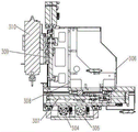
FIG. 6 is a cross-sectional view taken along line D-D of FIG. 5;
FIG. 7 is a cross-sectional view taken along line E-E of FIG. 5;
FIG. 8 is an isometric view of the outfeed module of FIG. 1;
FIG. 9 is a top view of the outfeed module of FIG. 1;
the above figures contain the following reference numerals.
| Reference numerals | Name (R) | Reference numerals | Name (R) | Reference numerals | Name (R) |
| 100 | |
304 | First |
401 | Discharging screw rod |
| 110 | |
305 | Second |
402 | |
| 200 | |
306 | First transverse |
403 | |
| 201 | |
307 | First |
404 | First discharge |
| 202 | First feeding pneumatic push block | 308 | |
405 | Second discharge |
| 204 | |
309 | First |
406 | Third processing |
| 205 | |
310 | Drilling a |
407 | |
| 206 | Second feeding |
311 | Second transverse moving |
408 | |
| 208 | Feeding guide rail | 312 | Second |
409 | |
| 300 | |
313 | |
410 | |
| 301 | First processing |
314 | Second |
411 | |
| 302 | Second processing |
315 | |
500 | Strip-shaped |
| 303 | |
400 | Discharging module |
Detailed Description
Reference will now be made in detail to embodiments of the present invention, examples of which are illustrated in the accompanying drawings, wherein like or similar reference numerals refer to the same or similar elements or elements having the same or similar function throughout. The embodiments described below with reference to the accompanying drawings are illustrative only for the purpose of explaining the present invention, and are not to be construed as limiting the present invention.
In the description of the present invention, it should be understood that the orientation or positional relationship referred to in the description of the orientation, such as the upper, lower, front, rear, left, right, etc., is based on the orientation or positional relationship shown in the drawings, and is only for convenience of description and simplification of description, and does not indicate or imply that the device or element referred to must have a specific orientation, be constructed and operated in a specific orientation, and thus, should not be construed as limiting the present invention.
In the description of the present invention, the meaning of a plurality of means is one or more, the meaning of a plurality of means is two or more, and more than, less than, more than, etc. are understood as excluding the present number, and more than, less than, etc. are understood as including the present number. If the first and second are described for the purpose of distinguishing technical features, they are not to be understood as indicating or implying relative importance or implicitly indicating the number of technical features indicated or implicitly indicating the precedence of the technical features indicated.
In the description of the present invention, unless otherwise explicitly limited, terms such as arrangement, installation, connection and the like should be understood in a broad sense, and those skilled in the art can reasonably determine the specific meanings of the above terms in the present invention in combination with the specific contents of the technical solutions.
Referring to fig. 1 to 9, the apparatus for processing a strip-shaped raw material according to the first aspect of the present embodiment includes: a base 100; the feeding module 200 is arranged at the left side of the base 100, and the feeding module 200 can clamp the strip-shaped raw material 500 and convey the raw material to the right; the discharging module 400 is arranged on the right side of the base 100, and the discharging module 400 can clamp and cut the strip-shaped raw material 500 and convey the raw material to the right; and a processing module 300 disposed on the base 100, the processing module 300 being located between the feeding module 200 and the discharging module 400, the processing module 300 including a drilling assembly 310 and a tapping assembly 3315 sequentially arranged in a left-right direction.
By applying the long strip-shaped raw material processing equipment, in the processing process, the long strip-shaped raw material 500 can be fed into the feeding module 200 from the left side, then the long strip-shaped raw material 500 is conveyed to the right side to the processing module 300 under the driving of the feeding module 200 or the discharging module 400, the drilling processing and the tapping processing are completed by the drilling assembly 310 and the tapping assembly 315 in sequence, then the processed part is cut off and conveyed to the right side by the discharging module 400, and the discharging is completed; in the initial stage, when the strip-shaped raw material 500 does not reach the discharging module 400, the feeding module 200 can drive the strip-shaped raw material 500 to be conveyed rightwards, so that the processing module 300 can process the raw material conveniently; when the strip-shaped raw material 500 at the feeding module 200 is used up, the discharging module 400 can drive the strip-shaped raw material 500 to be conveyed rightwards, and the rest one section of strip-shaped raw material 500 is fully utilized; the utilization rate of the strip-shaped raw material 500 can be effectively improved, and the quantity of the strip-shaped raw material 500 which cannot be used for processing is greatly reduced due to the limitation of the equipment structure.
In a second aspect of this embodiment, a method for processing a strip-shaped raw material is further provided, where the method for processing a strip-shaped raw material 500 by using the above strip-shaped raw material processing apparatus is characterized by including the following steps: s100, controlling the feeding module 200 or the discharging module 400 to convey the strip-shaped raw material 500 to the right to the drilling assembly 3310 of the processing module 300; s200, controlling the processing module 300 to enable the drilling assembly 310 to drill the strip-shaped raw material 500; s300, controlling the feeding module 200 or the discharging module 400 to convey the strip-shaped raw material 500 to the right to the tapping assembly 315 of the processing module 300; s400, controlling the processing module 300 to enable the tapping assembly 315 to tap the processed hole in the long strip-shaped raw material 500; s500, controlling the feeding module 200 or the discharging module 400 to convey the strip-shaped raw material 500 rightwards, and then controlling the discharging module 400 to cut off and discharge the processed part.
In step S100, the feeding module 200 or the discharging module 400 can be flexibly selected to transport the strip-shaped raw material according to actual needs, for example, after the feeding is started, the strip-shaped raw material 500 is not transported to the discharging module 400, the feeding module 200 can be controlled to drive the strip-shaped raw material 500 to move rightward, and the drilling and tapping processes are completed; when the raw material is about to be used up and the feeding module 200 has no raw material, the discharging module 400 can be controlled to drive the strip-shaped raw material 500 to move backwards, and the remaining strip-shaped raw material 500 is fully utilized; in the usual processing process, the feeding module 200 or the discharging module 400 can be flexibly selected to finish the rightward conveying of the strip-shaped raw material 500, and the feeding module 200 is preferably adopted to finish the conveying.
As shown in fig. 3, the feeding module 200 includes: a feeding frame 205 adapted to pass the strip-shaped raw material 500 in the left-right direction; the second feeding pneumatic pushing block 206 is arranged on the feeding frame 205, and the second feeding pneumatic pushing block 206 can press the strip-shaped raw material 500 downwards and enable the strip-shaped raw material 500 to be downwards abutted against the feeding frame 205; the feeding translation mechanism is arranged on the base 100 and is used for driving the feeding frame 205 to translate left and right; at this time, in step S100, when the feeding module 200 is needed to feed, the second feeding pneumatic pushing block 206 may be controlled to press the strip-shaped raw material 500 downward, so that the strip-shaped raw material 500 and the feeding frame 205 are relatively fixed, then the feeding translation mechanism drives the feeding frame 205 to move rightward, and then the second feeding pneumatic pushing block 206 is reset to complete the rightward conveying of the strip-shaped raw material 500; of course, the feeding translation mechanism can also be directly driven by a linear motor, or a motor gear and rack mechanism and the like can drive the feeding frame 205 to move left and right; the second feeding pneumatic push block 206 comprises a driving cylinder and a push block, the driving cylinder can drive the push block to move downwards, the strip-shaped raw material 500 is pressed on the feeding frame 205, and at the moment, the feeding frame 205 moves rightwards to drive the strip-shaped raw material 500 to move rightwards through friction force.
Specifically, as shown in fig. 3, the feeding translation mechanism includes: the feeding screw rod 204 is rotatably connected to the base 100, the feeding screw rod 204 extends along the left-right direction, a feeding nut is in threaded fit with the feeding screw rod 204, and the feeding nut is connected with the feeding frame 205; the servo system is arranged on the base 100 and is used for driving the feeding screw rod 204 to rotate; specifically, the servo system comprises a plurality of servo motors which are used for driving all screw rods in the whole processing equipment, namely the processing device, so as to complete servo control.
As shown in fig. 3, in order to ensure the smoothness of the left and right movement of the feeding frame 205 relative to the base 100, the feeding module 200 includes a feeding guide rail 208, the feeding guide rail 208 is disposed on the base 100, the feeding guide rail 208 extends in the left and right direction, and the feeding frame 205 is slidably fitted with the feeding guide rail 208; here, the servo mechanism can drive the feeding screw 204 to rotate, so that the feeding nut drives the feeding frame 205 to slide left and right on the feeding guide rail 208; specifically, there are two feeding guide rails 208, and a certain clearance has between two feeding guide rails 208 for hold servo motor and lead screw and bear the mechanism such as the bearing of lead screw, and cradle 205 sets up on two feeding guide rails 208, has guaranteed its stability in the middle of the translation process.
As shown in fig. 3, the feeding module 200 further includes: the feeding positioning frame 201 is arranged on the base 100, the feeding positioning frame 201 is positioned on the left side of the feeding frame 205, and the strip-shaped raw materials 500 can sequentially penetrate through the feeding positioning frame 201 and the feeding frame 205 from left to right; the first feeding pneumatic pushing block 202 is arranged on the feeding positioning frame 201, and the first feeding pneumatic pushing block 202 can push the strip-shaped raw material 500 backwards and enable the strip-shaped raw material 500 to be abutted against the feeding positioning frame 201 backwards; in the feeding process, the strip-shaped raw material 500 firstly passes through the feeding positioning frame 201 from left to right and then passes through the feeding frame 205; the first feeding pneumatic push block 202 also comprises a driving air cylinder and a horizontally moving push block, the driving air cylinder can drive the horizontal push block to push the strip-shaped raw material 500 backwards, so that the strip-shaped raw material 500 is backwards abutted against the feeding positioning frame 201 to complete positioning in the front-back direction; wherein, in order to guarantee the stability of the back-and-forth movement of the push block, a plurality of linear bearings are connected between the push block and the feeding positioning frame 201.
As shown in fig. 3, the feeding frame 205 is provided with a positioning cylinder and a positioning block, when feeding, the positioning cylinder can drive the positioning block to extend out, so as to prevent the strip-shaped raw material 500 from moving rightwards, in the process of charging before step S100, the positioning block is controlled to extend out, the positioning block can prevent the strip-shaped raw material from moving rightwards, at this time, the servo system can record the position of the current feeding frame 205, the positioning cylinder drives the positioning block to retract, when the second feeding pneumatic pushing block 206 pushes down the strip-shaped raw material 500 and the feeding frame 205 moves rightwards in step S100, the distance of the rightward movement of the feeding frame 205 is the distance of the rightward movement of the strip-shaped raw material 500, thereby the servo system can determine the initial position of the strip-shaped raw material 500 through the positioning function of the positioning block, and then accurately control the distance of the rightward feeding of the strip-shaped raw material 500.
As shown in fig. 8 and 9, the discharging module 400 further includes: the discharging translation frame 403 is movably arranged on the base 100, and the strip-shaped raw material 500 can penetrate through the discharging translation frame 403 along the left-right direction; the discharging clamping mechanism is arranged on the discharging translation frame 403 and can push the strip-shaped raw material 500 to enable the strip-shaped raw material 500 to abut against the discharging translation frame 403; the discharging translation mechanism is arranged on the base 100 and used for driving the discharging translation frame 403 to move left and right; at this time, in step S500, the discharging clamping mechanism can clamp the strip-shaped raw material 500, then cut off the processed part of the strip-shaped raw material 500, and then the discharging translation frame 403 drives the discharging clamping mechanism to move rightward, so as to output the cut-off part rightward; or the feeding module 200 is controlled to drive the strip-shaped raw material 500 to move rightwards, and the cut part is ejected rightwards.
The processing equipment further comprises a detection device arranged on the base 100, the detection device is positioned on one side of the feeding module 200, and the detection device is used for detecting whether the long strip-shaped raw material 500 exists at the position of the feeding module 200; in steps S100 and S300, when the detection device detects that the strip-shaped raw material 500 on the feeding module 200 is used up, the discharging module 400 can be switched to drive the strip-shaped raw material 500 to move rightward, so as to fully utilize the remaining strip-shaped raw material 500, and simultaneously, the raw material transportation mode can be automatically switched according to the remaining length of the strip-shaped raw material 500; it can be understood that the detecting device can detect whether there is any strip-shaped raw material 500 on the feeding module 200 in various ways, for example, a contact switch capable of being triggered by the strip-shaped raw material 500 is arranged on the feeding module 200, and if the contact switch is not triggered, it can be determined that there is no strip-shaped raw material 500 on the feeding module 200; can also be through setting up photoelectric switch above feed module 200, when rectangular shape raw materials 500 blocks photoelectric switch's light, can judge that there is rectangular shape raw materials 500 on the feed module 200.
Specifically, the detecting device can also play a role in the feeding step before step S100, specifically, in the charging step before step S100, the positioning cylinder controls the positioning block to extend out, the strip-shaped raw material 500 is inserted from the left side of the processing equipment, passes through the feeding positioning frame 201 and extends into the feeding frame 205 and then abuts against the positioning block, at this time, a button on the equipment is pressed, and if the detecting device detects that the strip-shaped raw material 500 exists on the feeding module 200, the detecting device can control the positioning cylinder to retract the positioning block to start production; if the detection device does not detect the strip-shaped raw material 500 on the feeding module 200, an alarm can be given to remind the user to feed materials again.
On the other hand, the servo system records and accurately controls the distance of the strip-shaped raw material 500 fed rightwards, and can also switch to move the strip-shaped raw material 500 rightwards under the drive of the feeding module 200 or the discharging module 400; specifically, when the moving position of the strip-shaped raw material 500 recorded by the servo system is smaller than the distance between the initial position of the strip-shaped raw material 500 and the discharging module 400, and the right end of the strip-shaped raw material 500 does not reach the discharging module 400, the feeding module 200 is controlled to convey the strip-shaped raw material 500 to the right; and when rectangular shape raw materials 500 right-hand member has arrived ejection of compact module 400, and when still having rectangular shape raw materials 500 on the feeding module 200, can also drive rectangular shape raw materials 500 with ejection of compact module 400 and move right with feeding module 200, the preferred feeding module 200 that adopts this moment drives rectangular shape raw materials 500 and moves right.
In the method for processing the elongated raw material of the present embodiment, the four steps S100 to S400 are often required to be executed repeatedly before the right end of the elongated raw material 500 reaches the discharging module 400, that is, the drilling and tapping processes of a plurality of parts are performed on the elongated raw material 500 as required, and the step S500 is executed to discharge the elongated raw material 500 after the drilling and tapping processes reach the discharging module 400.
As shown in fig. 8 and 9, the discharging module 400, which is the discharging device of the present embodiment, further includes: a frame; the discharging translation frame 403 is movably arranged on the rack, and the strip-shaped raw material 500 can penetrate through the discharging translation frame 403 along the left-right direction; the discharging clamping mechanism is arranged on the discharging translation frame 403, the discharging clamping mechanism comprises at least two clamping parts which are arranged at intervals along the left-right direction, and the clamping parts can push the strip-shaped raw material 500 and enable the strip-shaped raw material 500 to abut against the discharging translation frame 403; the discharging translation mechanism is arranged on the rack and used for driving the discharging translation frame 403 to move left and right; and the blanking mechanism is arranged on the rack and can cut off the strip-shaped raw material 500 in the gap between the two clamping parts.
By using the above-mentioned discharging device, in step S500, the strip-shaped raw material 500 can be sent to the discharging translation frame 403, then the two clamping parts of the discharging clamping mechanism are controlled to clamp the strip-shaped raw material 500 together with the discharging translation frame 403, so that the portions of the strip-shaped raw material 500 to be divided are located at the gap between the two holding portions, then the blanking mechanism is controlled to enter the gap to cut off the strip-shaped raw material 500, then the discharging translation mechanism is controlled to drive the discharging translation frame 403 to move rightwards, the strip-shaped raw material 500 and the cut part are driven to move rightwards together, then the two clamping parts are controlled to release clamping, under the condition that need not to set up alone and snatch the mechanism, can carry out the ejection of compact with the work piece that the processing was accomplished when accomplishing rectangular shape raw materials 500 feeding, effectively improved the space utilization and the mechanism rate of reuse of transportation and unloading two parts structure.
The discharging translation mechanism can drive the discharging translation frame 403 to move left and right in various ways, for example, the motor drives the rack-and-pinion mechanism to drive the discharging translation frame 403, or the linear motor, the air cylinder or the hydraulic cylinder drives the discharging translation frame 403 to move left and right, etc.
As shown in fig. 8 and 9, the discharging clamping mechanism includes a first discharging pneumatic pushing block 404 and a second discharging pneumatic pushing block 405 disposed on the discharging translational frame 403, the first discharging pneumatic pushing block 404 and the second discharging pneumatic pushing block 405 are disposed at an interval in the left-right direction, and the first discharging pneumatic pushing block 404 and the second discharging pneumatic pushing block 405 can push the strip-shaped raw material 500 rightward and make the strip-shaped raw material 500 abut against the discharging translational frame 403 downward; in the middle of step S500, first ejection of compact pneumatic ram 404 is used for the part that the centre gripping rectangular shape raw materials 500 need not the ejection of compact, second ejection of compact pneumatic ram 405 is used for the part that the centre gripping rectangular shape raw materials 500 has drilled and the tapping finishes the needs ejection of compact in the middle of, the limit between two parts just in time is located the position between first ejection of compact pneumatic ram 404 and the second ejection of compact pneumatic ram 405, blanking mechanism can stretch into the clearance between first ejection of compact pneumatic ram 404 and the second ejection of compact pneumatic ram 405 this moment, cut off rectangular shape raw materials 500, then ejection of compact translation frame 403 moves right, two ejection of compact pneumatic rams loosen, when the work piece ejection of compact that will process the completion, can also drive rectangular shape raw materials 500 and move right.
Of course, in step S500, the second discharging pneumatic pushing block 405 may be used to stick the portion to be cut off and then discharge the material to the right, and the operation of moving the strip-shaped raw material 500 to the right is performed by the feeding module 200.
It can be understood that the first discharging pneumatic pushing block 404 and the second discharging pneumatic pushing block 405 are similar in structure, and are driven by a driving cylinder to drive one pushing block, and the pushing block can push the strip-shaped raw material 500 to the right to abut against the discharging translation frame 403 of the strip-shaped raw material 500, so that the stability in cutting is ensured.
As shown in fig. 8, the discharging translation frame 403 is provided with a discharging guide 407, and the discharging guide 407 is located at the right side of the discharging translation frame 403; after the discharging translation frame 403 moves rightwards, the discharging guide 407 can be butted with a discharging port on the right side of the machine body, so that the cut workpiece can be discharged rightwards.
Specifically, as shown in fig. 8 and 9, the discharging translation mechanism includes: the discharging screw rod 401 is rotatably arranged on the rack, and the discharging screw rod 401 extends along the left and right directions; the discharging nut is in threaded fit with the discharging screw rod 401 and is connected with the discharging translation frame 403; the servo system is arranged on the rack and is used for driving the discharging screw rod 401 to rotate; wherein, the servo system drives the discharging screw rod 401 to rotate through the servo motor, so as to control the discharging translation frame 403 to move leftwards or rightwards.
The discharging translation mechanism further comprises a discharging guide rail 402 arranged on the rack, the discharging guide rail 402 extends along the left-right direction, and the discharging translation frame 403 is in sliding fit with the discharging guide rail 402; wherein, ejection of compact guide rail 402 has two, and the interval sets up in the frame, and ejection of compact lead screw 401 and the servo motor of drive ejection of compact lead screw 401 and mechanism such as shaft coupling all are located the space between two ejection of compact guide rails 402, and ejection of compact translation frame 403 can control the translation for ejection of compact guide rail 402, and stability is better.
As shown in fig. 9, the blanking mechanism includes: the blanking translation mechanism is arranged on the rack; a discharging motor 410 arranged on the discharging translation mechanism; the cutting wheel 411 is in driving connection with the blanking motor 410; the blanking translation mechanism can drive the blanking motor 410 to move forward, so that the cutting wheel 411 enters a position between the first discharging pneumatic push block 404 and the second discharging pneumatic push block 405; in step S500, after the first discharging pneumatic pushing block 404 and the second discharging pneumatic pushing block 405 clamp the strip-shaped raw material 500, the lower translation mechanism can drive the blanking motor 410 and the cutting wheel 411 to translate forward together, meanwhile, the blanking motor 410 drives the cutting wheel 411 to rotate, and the cutting wheel 411 can extend into a gap between the first discharging pneumatic pushing block 404 and the second discharging pneumatic pushing block 405 to cut off the strip-shaped raw material 500.
Specifically, unloading translation mechanism includes: the blanking screw 408 is rotatably arranged on the frame, and the blanking screw 408 extends along the front-back direction; the blanking nut is in threaded fit with the blanking screw 408 and is fixedly connected with the blanking motor 410; the servo system is arranged on the rack and is used for driving the blanking screw rod 408 to rotate; specifically, the servo system includes a motor for driving the feeding screw 408 to rotate, and the feeding screw 408 is driven to rotate to drive the feeding motor 410 and the cutting wheel 411 to move back and forth.
The blanking translation mechanism further comprises a blanking guide rail 409 arranged on the rack, the blanking guide rail 409 extends in the front-back direction, and the blanking motor 410 is in sliding fit with the blanking guide rail 409; specifically, there are two blanking guide rails 409, which are spaced apart from each other on the frame, and the blanking screw 408, the blanking nut, and a servo motor for driving the blanking screw 408 are all located in a space between the two blanking guide rails 409.
As shown in fig. 9, the discharging translation frame 403 is provided with an avoiding groove for avoiding the cutting wheel 411.
It can be understood that the discharging device, i.e. the discharging module 400, is a part of the processing equipment, i.e. the processing device in this embodiment; the frame of the discharging device can be regarded as a part of the base 100.
As shown in fig. 5 to 7, the processing apparatus of the present embodiment further includes an automatic drilling and tapping composite processing function, that is, an automatic drilling and tapping composite processing apparatus, which includes: a base 100; the feeding module 200 is arranged at the left side of the base 100, and the feeding module 200 can clamp the strip-shaped raw material 500 and convey the raw material to the right; the discharging module 400 is arranged on the right side of the base 100, and the discharging module 400 can clamp and cut the strip-shaped raw material 500 and convey the raw material to the right; a processing module 300 disposed on the base 1000, the processing module 300 being located between the feeding module 200 and the discharging module 400; the processing module 300 includes: a triaxial moving assembly provided on the base 100; the drilling assembly 3310 and the tapping assembly 315 are disposed on a three-axis moving assembly, the drilling assembly 310 and the tapping assembly 315 are disposed at intervals in the left-right direction, and the three-axis moving assembly is used for driving the drilling assembly 310 and the tapping assembly 315 to move.
By applying the automatic drilling and tapping combined machining device, in the steps of S200 and S400, the strip-shaped raw material 500 can be fed into the feeding module 200 from the left side, then the strip-shaped raw material 500 is conveyed to the right side to the machining module 300 under the driving of the feeding module 200 or the discharging module 400, the drilling and tapping machining is completed by the drilling assembly 310 and the tapping assembly 315 in sequence, and then the machined part is cut off and conveyed to the right side by the discharging module 400, so that the discharging is completed; in the middle of the course of working, the triaxial removes the subassembly and can drive drilling subassembly 310 and tapping subassembly 315 along the three direction removal of X axle, Y axle and Z axle, removes drilling subassembly 310 and tapping subassembly 315 and carries out drilling and tapping behind the accurate position, has effectively improved drilling and tapping precision in the middle of the bar raw materials course of working.
It will be appreciated that the three-axis movement assembly is capable of moving the drilling assembly 310 and the tapping assembly 315 in three directions, namely, left and right, front and back, and up and down, as shown in fig. 1-9.
The three-axis moving assembly can drive the drilling assembly 310 and the tapping assembly 315 to move along three directions in various ways, for example, two three-axis portal frames respectively drive the drilling assembly 310 and the tapping assembly 315 to move; the drilling assembly 310 and the tapping assembly 315 may also be moved by a three-axis robotic arm.
Specifically, the triaxial moving assembly includes: a first transverse screw 304 and a second transverse screw 305 rotatably disposed on the base 100, the first transverse screw 304 and the second transverse screw 305 extending in the left-right direction, the first transverse screw 304 and the second transverse screw 305 being disposed at intervals in the front-back direction; a first transverse nut and a second transverse nut which are respectively in threaded fit with the first transverse screw 304 and the second transverse screw 305; the first transverse frame 306 is movably arranged on the base 100, the first transverse frame 306 is connected with a first transverse nut, and the drilling assembly 310 is arranged on the first transverse frame 306; the second transverse frame 311 is movably arranged on the base 100, the second transverse frame 311 is connected with a second transverse nut, and the tapping component 315 is arranged on the second transverse frame 311; and the servo system is arranged on the base 100 and is used for driving the first transverse screw rod 304 and/or the second transverse screw rod 305 to rotate.
The servo system comprises two independent servo motors which respectively drive the first transverse screw rod 304 and the second transverse screw rod 305 to rotate, in step S200, the servo motors can adjust the position of the drilling assembly 310 in the left-right direction by driving the first transverse screw rod 304 to rotate, and in step S400, the servo motors can adjust the position of the tapping assembly 315 in the left-right direction by driving the second transverse screw rod 305 to rotate.
The drilling assembly 310 comprises a drilling motor and a drill bit arranged on the drilling motor, the drilling motor drives the drill bit to rotate, and the drilling motor can be driven by the three-axis moving assembly to move so as to drive the drill bit to change a drilling position; similarly, the tapping assembly 315 also includes a tapping motor and a tapping head, the tapping motor is used to drive the tapping head to rotate, and the tapping motor can also be moved under the drive of the three-axis moving assembly.
As shown in fig. 6, the triaxial moving assembly includes: a first longitudinal screw 307 rotatably disposed on the first traverse frame 306, the first longitudinal screw 307 extending in the front-rear direction; a first longitudinal nut in threaded engagement with the first longitudinal screw 307; the first translation frame 308 is movably arranged on the first transverse frame 306, the first translation frame 308 is connected with the first longitudinal nut, and the drilling assembly 310 is arranged on the first translation frame 308; the servo system can drive the first longitudinal screw 307 to rotate; in step S200, the servo system correspondingly drives the first longitudinal screw 307 to rotate to adjust the front and rear positions of the first translation frame 308 and the drilling assembly 310, so that the drilling position is accurate.
Specifically, in order to ensure smooth forward and backward movement of the first translation frame 308, the first transverse frame 306 is provided with a longitudinal guide rail, the guide rail extends in the forward and backward directions, and the first translation frame 308 is in sliding fit with the longitudinal guide rail.
As shown in fig. 6, the triaxial moving assembly includes: a first vertical screw rod 309 rotatably disposed on the first translation frame 308, the first vertical screw rod 309 extending in an up-down direction; the first vertical nut is in threaded fit with the first vertical screw rod 309 and is connected with the drilling assembly 310; the servo system is used for driving the first vertical screw rod 309 to rotate; in step S200, after the drill of the drilling assembly 310 is located right above the drilling position, the servo motor drives the first vertical screw 309 to rotate, so as to drive the drilling motor and the drill to descend, thereby drilling the hole in the strip-shaped raw material 500.
Wherein, be provided with vertical guide rail on the first translation frame 308, vertical guide rail extends along upper and lower direction, drilling subassembly 310 and vertical guide rail sliding fit.
As shown in fig. 7, the triaxial moving assembly includes: a second longitudinal screw 312 rotatably disposed on the second traverse frame 311, the second longitudinal screw 312 extending in the front-rear direction; a second longitudinal nut in threaded engagement with the second longitudinal screw 312; the second translation frame 313 is movably arranged on the second transverse frame 311, the second translation frame 313 is connected with the second longitudinal nut, and the tapping component 315 is arranged on the second translation frame 313; the servo system can drive the second longitudinal screw 312 to rotate; in step S400, the servo motor drives the second longitudinal screw 312 to rotate, so that the second translation frame 313 and the tapping assembly 315 move back and forth, and the front and rear positions of the tapping assembly 315 are adjusted.
Wherein, the triaxial removes the subassembly and includes: the second vertical screw rod 314 is rotatably arranged on the second translation frame 313, the second vertical screw rod 314 extends along the up-down direction, and the servo system can drive the second vertical screw rod 314 to rotate; the second vertical nut is in threaded fit with the second vertical screw rod 314 and is connected with the tapping assembly 315; in step S400, after the tapping assembly 315 moves to a position right above the tapping position, the servo system drives the second vertical screw 314 to rotate, so that the tapping motor and the tapping head descend together to perform tapping.
As shown in fig. 4 and 5, the processing apparatus further includes a first processing pneumatic pushing block 301 and a second processing pneumatic pushing block 302 which are arranged on the base 100, the first processing pneumatic pushing block 301 is located at the front side of the drilling assembly 310, the second processing pneumatic pushing block 302 is located at the front side of the tapping assembly 315, and both the first processing pneumatic pushing block 301 and the second processing pneumatic pushing block 302 can push the strip-shaped raw material 500 backwards; in step S200, the first processing pneumatic pushing block 301 and the base 100 can clamp the strip-shaped raw material 500 together, so as to ensure that the strip-shaped raw material 500 is stable in the position of the drilling station and ensure that the drilling position is accurate; in step S400, the second pneumatic pushing block 302 can clamp the strip-shaped material 500 together with the base 100, so as to ensure that the strip-shaped material 500 is stable in the tapping position and the tapping position is accurate.
The processing device further comprises a third processing pneumatic push block 406 arranged on the base 100, the third processing pneumatic push block 406 is positioned on the left side of the discharging module 400, and the third processing pneumatic push block 406 can press the strip-shaped raw material 500 downwards; during the drilling or tapping process, the third pneumatic pushing block 406 can push down the strip-shaped material 500 to ensure the accurate upper and lower positions.
When drilling and tapping add man-hour, the built-in spray set of processing equipment can be towards drilling position and tapping position injection coolant liquid, and base 100 below is provided with circulation module 110, and circulation module 110 includes funnel and circulating pump, and the cooling back is accomplished to the coolant liquid, can fall into in the middle of the funnel downwards under the action of gravity, then collects and get into the circulating pump, gets into the spout blowout under the drive of circulating pump, has accomplished the cyclic utilization of coolant liquid.
The embodiments of the present invention have been described in detail with reference to the accompanying drawings, but the present invention is not limited to the above embodiments, and various changes can be made within the knowledge of those skilled in the art without departing from the gist of the present invention.
Claims (10)
1. The utility model provides an automatic change and bore compound processingequipment of attacking which characterized in that includes:
a base (100);
the feeding module (200) is arranged on the left side of the base (100), and the feeding module (200) can clamp the strip-shaped raw material (500) and convey the raw material to the right;
the discharging module (400) is arranged on the right side of the base (100), and the discharging module (400) can clamp and cut off the strip-shaped raw material (500) and convey the raw material to the right;
a processing module (300) disposed on the base (100), the processing module (300) being located between the infeed module (200) and the outfeed module (400);
the processing module (300) comprises:
a three-axis moving assembly disposed on the base (100);
drilling subassembly (310) and tapping subassembly (315), set up on the triaxial removes the subassembly, drilling subassembly (310) with tapping subassembly (315) sets up along left right direction interval, the triaxial removes the subassembly and is used for the drive drilling subassembly (310) with tapping subassembly (315) remove.
2. The automated drill-and-tap compound processing device of claim 1, wherein the three-axis movement assembly comprises:
a first transverse screw rod (304) and a second transverse screw rod (305) which are rotatably arranged on the base (100), wherein the first transverse screw rod (304) and the second transverse screw rod (305) extend along the left-right direction, and the first transverse screw rod (304) and the second transverse screw rod (305) are arranged at intervals along the front-back direction;
a first and a second transverse nut in threaded engagement with said first and said second transverse screw (304, 305), respectively;
a first traverse frame (306) movably disposed on the base (100), the first traverse frame (306) being connected with the first traverse nut, the drilling assembly (310) being disposed on the first traverse frame (306);
the second transverse frame (311) is movably arranged on the base (100), the second transverse frame (311) is connected with the second transverse nut, and the tapping component (315) is arranged on the second transverse frame (311);
a servo system arranged on the base (100), wherein the servo system is used for driving the first transverse screw rod (304) and/or the second transverse screw rod (305) to rotate.
3. The automated drill-and-tap compound processing device of claim 2, wherein the three-axis movement assembly comprises: the first longitudinal screw rod (307) is rotationally arranged on the first transverse frame (306), and the first longitudinal screw rod (307) extends along the front-back direction;
a first longitudinal nut in threaded engagement with the first longitudinal screw (307);
a first translational frame (308) movably disposed on the first transverse frame (306), the first translational frame (308) being connected with the first longitudinal nut, the drilling assembly (310) being disposed on the first translational frame (308);
the servo system can drive the first longitudinal screw rod (307) to rotate.
4. The automated drilling and tapping combined machining device according to claim 3, wherein the first transverse moving frame (306) is provided with a longitudinal guide rail extending in a front-rear direction, and the first transverse moving frame (308) is slidably fitted with the longitudinal guide rail.
5. The automated drill-and-tap compound processing device of claim 3, wherein the three-axis movement assembly comprises: the first vertical screw rod (309) is rotatably arranged on the first translation frame (308), and the first vertical screw rod (309) extends along the vertical direction;
the first vertical nut is in threaded fit with the first vertical screw rod (309), and the first vertical nut is connected with the drilling assembly (310);
the servo system is used for driving the first vertical screw rod (309) to rotate.
6. The automatic drilling and tapping combined machining device according to claim 5, wherein the first translation frame (308) is provided with vertical guide rails extending in an up-and-down direction, and the drilling assembly (310) is in sliding fit with the vertical guide rails.
7. The automated drill-and-tap compound processing device of claim 3, wherein the three-axis movement assembly comprises:
the second longitudinal screw rod (312) is rotatably arranged on the second transverse moving frame (311), and the second longitudinal screw rod (312) extends along the front-back direction;
a second longitudinal nut in threaded engagement with the second longitudinal screw (312);
the second translation frame (313) is movably arranged on the second transverse frame (311), the second translation frame (313) is connected with the second longitudinal nut, and the tapping assembly (315) is arranged on the second translation frame (313);
the servo system can drive the second longitudinal screw rod (312) to rotate.
8. The automated drill-and-tap compound processing device of claim 7, wherein the three-axis movement assembly comprises:
the second vertical screw rod (314) is rotatably arranged on the second translation frame (313), the second vertical screw rod (314) extends along the vertical direction, and the servo system can drive the second vertical screw rod (314) to rotate;
and the second vertical nut is in threaded fit with the second vertical screw rod (314), and the second longitudinal nut is connected with the tapping assembly (315).
9. The automated drilling and tapping combined machining device according to claim 1, further comprising a first machining pneumatic pushing block (301) and a second machining pneumatic pushing block (302) which are arranged on the base (100), wherein the first machining pneumatic pushing block (301) is located on the front side of the drilling assembly (310), the second machining pneumatic pushing block (302) is located on the front side of the tapping assembly (315), and the first machining pneumatic pushing block (301) and the second machining pneumatic pushing block (302) can both push the elongated raw material (500) backwards.
10. The automated drill-and-tap composite processing apparatus according to claim 9, further comprising a third processing pneumatic pusher (406) provided on the base (100), the third processing pneumatic pusher (406) being located at the left side of the outfeed module (400), the third processing pneumatic pusher (406) being capable of pressing down the elongated feedstock (500).
Priority Applications (1)
| Application Number | Priority Date | Filing Date | Title |
|---|---|---|---|
| CN202210353234.9A CN114700743A (en) | 2022-04-02 | 2022-04-02 | Automatic change and bore compound processingequipment of attacking |
Applications Claiming Priority (1)
| Application Number | Priority Date | Filing Date | Title |
|---|---|---|---|
| CN202210353234.9A CN114700743A (en) | 2022-04-02 | 2022-04-02 | Automatic change and bore compound processingequipment of attacking |
Publications (1)
| Publication Number | Publication Date |
|---|---|
| CN114700743A true CN114700743A (en) | 2022-07-05 |
Family
ID=82172137
Family Applications (1)
| Application Number | Title | Priority Date | Filing Date |
|---|---|---|---|
| CN202210353234.9A Pending CN114700743A (en) | 2022-04-02 | 2022-04-02 | Automatic change and bore compound processingequipment of attacking |
Country Status (1)
| Country | Link |
|---|---|
| CN (1) | CN114700743A (en) |
-
2022
- 2022-04-02 CN CN202210353234.9A patent/CN114700743A/en active Pending
Similar Documents
| Publication | Publication Date | Title |
|---|---|---|
| CN113020983A (en) | Efficient lock core cover grooving process automatic processing equipment | |
| CN111843583A (en) | Full-automatic precision machining system of robot-assisted numerically controlled lathe | |
| CN112025537B (en) | Part honing system | |
| CN111515414A (en) | Machine vision auxiliary unmanned numerical control turning machine tool | |
| CN103639472A (en) | Numerical control drilling machine | |
| CN114905281B (en) | Profile deep processing and cutting integrated machine | |
| CN217193817U (en) | Long strip-shaped raw material processing equipment | |
| CN217045386U (en) | Automatic drilling and tapping combined machining device | |
| CN217194168U (en) | Discharging device and processing device | |
| CN210412545U (en) | Double-spindle double-channel numerical control lathe | |
| CN203696012U (en) | Digital controlled drilling machine | |
| CN114700743A (en) | Automatic change and bore compound processingequipment of attacking | |
| CN114770113A (en) | Long strip-shaped raw material processing equipment and method | |
| CN203390205U (en) | Automatic rolling post-feeding device for numerical control lathe | |
| CN213034792U (en) | Numerical control drilling device with automatic feeding and discharging structure | |
| CN111251007B (en) | Production line equipment of bearing roller shaft | |
| CN109940439B (en) | Automatic loading and unloading device for rotating shaft numerical control lathe and numerical control milling machine | |
| CN113145889B (en) | Numerical control drilling machine | |
| CN105500105A (en) | Turing center with inverted spindle | |
| JP5275663B2 (en) | Modified cross section bar supply device and processing device | |
| CN217571749U (en) | Automatic tool changing type long strip raw material processing device | |
| CN212019987U (en) | Towing hook nut production equipment for alternately machining two ends of translational workpiece | |
| CN218397159U (en) | Multi-direction feeding positioning device | |
| CN218363568U (en) | Feeding device | |
| CN214979172U (en) | Efficient lock core cover grooving process automatic processing equipment |
Legal Events
| Date | Code | Title | Description |
|---|---|---|---|
| PB01 | Publication | ||
| PB01 | Publication | ||
| SE01 | Entry into force of request for substantive examination | ||
| SE01 | Entry into force of request for substantive examination |