CN114646868B - Intelligent test needle mold equipment for FPC performance test - Google Patents
Intelligent test needle mold equipment for FPC performance test Download PDFInfo
- Publication number
- CN114646868B CN114646868B CN202210552121.1A CN202210552121A CN114646868B CN 114646868 B CN114646868 B CN 114646868B CN 202210552121 A CN202210552121 A CN 202210552121A CN 114646868 B CN114646868 B CN 114646868B
- Authority
- CN
- China
- Prior art keywords
- retest
- test
- marking
- fpc
- probe
- Prior art date
- Legal status (The legal status is an assumption and is not a legal conclusion. Google has not performed a legal analysis and makes no representation as to the accuracy of the status listed.)
- Active
Links
Images


Classifications
-
- G—PHYSICS
- G01—MEASURING; TESTING
- G01R—MEASURING ELECTRIC VARIABLES; MEASURING MAGNETIC VARIABLES
- G01R31/00—Arrangements for testing electric properties; Arrangements for locating electric faults; Arrangements for electrical testing characterised by what is being tested not provided for elsewhere
- G01R31/28—Testing of electronic circuits, e.g. by signal tracer
Abstract
The invention relates to the technical field of FPC (flexible printed circuit) testing, and discloses intelligent testing pin die equipment for FPC performance testing. The performance of the FPC soft board is detected through the testing component, the detection result is input into a computer for judgment, the FPC soft board with the abnormal detection of the testing component is retested through the retesting component, and when the retesting result of the abnormal area of the first detection result is good in performance, the contact abnormality of the FPC soft board belonging to the testing component during the detection of the testing component is shown; when the retest result of the area with good first detection result is abnormal, the contact abnormality of the retest component is indicated when the retest component is detected by the FPC soft board, and a unified marking mode is adopted for the two contact abnormalities; and when the repeated test result of the abnormal area of the first test result is abnormal performance, the FPC soft board is indicated to have abnormal performance, and the FPC soft board is marked with abnormal performance.
Description
Technical Field
The invention relates to the technical field of FPC (flexible printed circuit) testing, in particular to intelligent testing needle mold equipment for FPC performance testing.
Background
Flexible printed circuit board) is called a flexible board for short, the flexible board is commonly called an FPC flexible board in the industry, and the flexible printed circuit board is a printed circuit board made of flexible insulating base materials and has many advantages that rigid printed circuit boards do not have, such as high wiring density, light weight, thin thickness, good bending property and the like. In order to ensure the quality of an electronic product using the FPC, the FPC needs to be subjected to performance test after being produced;
the existing FPC testing equipment tests FPC through a testing jig; in the electrical performance testing procedure of a common FPC, manual feeding is needed, a probe is arranged on a lower jig, the FPC is placed on the lower jig and positioned through a pin during testing, the upper jig is lowered to press the FPC tightly, the probe is pricked at the position of the FPC to be tested, whether the FPC is conducted is tested, the testing result is displayed on a display screen, manual marking is conducted, full good products and non-full good products are distinguished manually, and a worker marks the FPC with a poor testing result and selects the FPC; in the long-term production process, the manual work easily makes mistakes or damages FPC, leads to the later stage paster to scrap, and the cost increase to and the problem of making mistakes is traced back the difficulty, consequently need replace manual operation process with automatic test.
At present, automatic testing equipment for FPC (flexible printed circuit) flexible boards is available in the market, but most of the equipment can grab the FPC flexible boards by replacing people with mechanical claws and place the FPC flexible boards in detection equipment, and when detection occurs, a test probe is not in good contact with a detection hole of the FPC flexible boards, so that pseudo-defective products are caused, and the use of finished FPC flexible boards is influenced; and when the defective products are detected, a plurality of abnormal areas may appear, the abnormal areas cannot be marked quickly and accurately, label leakage and label error easily occur, the test result of the product is influenced, and the defective products are leaked.
Disclosure of Invention
Technical scheme (I)
In order to solve the technical problems, the invention provides the following technical scheme: an intelligent testing pin die device for testing the FPC performance comprises a detection table, wherein a testing pin die mechanism is arranged on the detection table and comprises a testing assembly and a retesting assembly; when the testing component detects the performance of the FPC soft board to generate inferior products, the retesting component retests the FPC soft board; the retest assembly comprises a retest pin die, a marking assembly and a retest driver, wherein the retest driver drives the retest pin die and the marking assembly to contact the FPC soft board in an intermittent transmission mode, so that when the retest pin die descends, the marking assembly ascends and marks the FPC soft board; and an access device is arranged above the detection table and used for classifying and stacking the detected FPC soft boards.
Preferably, the test assembly comprises a test drive board, a test pin template is arranged at the bottom of the test drive board, a connecting rod is arranged on the periphery of the bottom of the test drive board and connected with the test pin template, and a spring is arranged on the periphery of the connecting rod; the test drive board drives the test pin template to test the FPC soft board.
Preferably, the connecting rod is slidably connected with the test drive board, the connecting rod is fixedly connected with the test pin template, and two ends of the spring are respectively fixedly connected with the test drive board and the test pin template; and compressing the spring through the test driving board to enable the test pin template to be in complete contact with the FPC soft board.
Preferably, an objective table is arranged in the middle of the upper surface of the detection table, and the retesting component is arranged at the bottom of the objective table; a positioning rod is arranged on the upper surface of the object stage and corresponds to a positioning hole in the FPC soft board; the object stage is provided with a plurality of groups of test probe holes, the positioning rod is positioned in a gap between each group of test probe holes, and the two sides of each test probe hole are provided with marking probe holes.
Preferably, the retest pin mold comprises a plurality of retest support plates, a retest probe is arranged above the retest support plates and corresponds to the test probe hole on the objective table, the retest drive is located at the bottom of the retest support plates, and the marking assembly is located above the retest pin mold.
Preferably, the marking assembly comprises a marking carrier plate, the marking carrier plate is located above the retest carrier plate, a perforation is formed in the marking carrier plate, so that the marking carrier plate can move on the retest probe, marking rods are arranged on the upper surface of the marking carrier plate and located on two sides of the perforation, electromagnetic ejection blocks are respectively arranged at the bottoms of the marking rods on each side, the electromagnetic ejection blocks are matched with the bottoms of the marking rods, and the electromagnetic ejection blocks are used for driving the marking rods to lift so that the marking rods mark the FPC soft board.
Preferably, the retest drive includes the retest motor, retest motor tip is provided with drive gear, be provided with umbrella-type tooth on the drive gear, umbrella-type tooth includes probe drive tooth and mark drive tooth, the retest support plate is close to one side of retest motor is provided with the probe bar tooth that moves up and moves down, drive gear is located move up between the probe bar tooth and the probe bar tooth that moves down, mark support plate one side is provided with the mark bar tooth, the mark bar tooth is located move down one side of probe bar tooth, probe drive tooth when rotating alternatively with move up probe bar tooth and move down probe bar tooth meshing for drive retest support plate and the mark support plate move up, so that retest, and drive after the retest support plate end move down and reset, the mark driving teeth are used for being meshed with the mark strip teeth after the retest carrier plate moves downwards to reset so as to drive the mark carrier plate to move downwards to reset.
Preferably, the access device comprises a storage assembly and a suction assembly, the suction assembly is located on the back of the detection table, the storage assembly comprises three containing boxes and one supply box, and the three containing boxes and the one supply box are located on the peripheral side of the suction assembly respectively.
Preferably, the suction assembly comprises a linear guide rail, a driving turntable is arranged above a sliding block of the linear guide rail, a suction motor is arranged above the driving turntable, an execution mechanical arm is arranged at the output end of the suction motor, the front end of the execution mechanical arm is connected with a suction mechanical arm, and a vacuum sucker is arranged at the front end of the suction mechanical arm.
(II) advantageous effects
Compared with the prior art, the invention provides intelligent testing needle mold equipment for FPC performance testing, which has the following beneficial effects:
1. the intelligent testing pin die equipment for the FPC performance test performs performance detection on the FPC soft board through the testing component, inputs a detection result into a computer for judgment, performs retesting on the FPC soft board with the abnormal detection result detected by the testing component through the retesting component, and indicates that the FPC soft board belongs to contact abnormity of the testing component during detection of the testing component when the retesting result of an abnormal area of the first detection result is good in performance; when the retest result of the area with good first detection result is abnormal in performance, the contact abnormality of the retest assembly is indicated when the FPC soft board is detected by the retest assembly, and a unified marking mode is adopted for the two contact abnormalities; and when the repeated test result of the abnormal area of the first test result is abnormal performance, the FPC soft board is indicated to have abnormal performance, and the FPC soft board is marked with abnormal performance.
2. This an intelligent test needle mould equipment for FPC capability test, through the FPC soft board to the detection performance anomaly, carry out the secondary retest, the retest motor drives the drive gear rotation of its tip, the probe drive tooth on the drive gear is at first engaged with the probe bar tooth that moves up, and through this probe bar tooth that moves up drive retest support plate rebound, at this moment retest support plate rebound, also promote mark support plate rebound at the same time, retest probe this moment under the drive of retest support plate, pass the test probe hole, and with FPC soft board contact, detect this FPC soft board once more, and combine the testing result with the result that the test assembly detected, judge that the part of anomaly belongs to the contact anomaly of test assembly or the electrically conductive anomaly of this FPC soft board through the computer.
3. This an intelligent test needle mould equipment for FPC capability test carries out corresponding mark to the FPC soft board after retesting through the mark subassembly: the driving gear continues rotating, the probe driving teeth rotate to be meshed with the downward-moving probe strip-shaped teeth and are separated from the upward-moving probe strip-shaped teeth, the probe driving teeth drive the retest support plate to move downward through the downward-moving probe strip-shaped teeth, and the marking support plate is static at the moment and can start to correspondingly mark abnormal areas.
4. The intelligent testing needle mold equipment for the FPC performance test drives the driving gear at the end part to rotate through the retest motor, when the testing component detects the abnormality of the FPC soft board, the retest component is required to carry out secondary detection on the FPC soft board, under the driving of the driving gear, the probe driving teeth on the driving gear are firstly meshed with the upward-moving probe strip-shaped teeth, and the retest support plate is driven to move upwards through the upward-moving probe strip-shaped teeth, and the marking support plate is also pushed to move upwards while the retest support plate moves upwards; when retesting is finished, the probe driving teeth are transferred to be meshed with the downward-moving probe strip-shaped teeth and separated from the upward-moving probe strip-shaped teeth, the probe driving teeth drive the retesting support plate to move downward through the downward-moving probe strip-shaped teeth, and the marking support plate is static and can start to correspondingly mark abnormal areas; after the marking is finished, the driving gear continues to rotate until the probe driving teeth are separated from the downward-moving probe strip teeth, the marking driving teeth on one side of the probe driving teeth rotate to be meshed with the marking strip teeth, the marking support plate is driven to move downwards through the marking strip teeth until the marking driving teeth are separated from the marking strip teeth, the marking support plate is contacted with the retesting support plate again, the retesting motor stops rotating, the probe driving teeth rotate for one circle and are meshed with the upward-moving probe strip teeth again, and when retesting is needed next time, the driving gear is driven by the retesting motor again to achieve retesting and marking.
Drawings
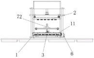
FIG. 1 is a schematic overall perspective view of the present invention;
FIG. 2 is a schematic perspective view of a part of the inspection apparatus of the present invention;
FIG. 3 is a schematic view of the overall front plan structure of the present invention;
FIG. 4 is a schematic diagram of a partially exploded configuration of a test assembly of the present invention;
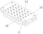
FIG. 5 is a perspective view of a portion of the stage of the present invention;
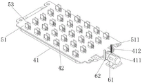
FIG. 6 is a schematic perspective view of a portion of a retest assembly in accordance with the present invention;
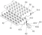
FIG. 7 is a schematic diagram of a partially exploded view of a retest assembly in accordance with the present invention;
FIG. 8 is a schematic view of the internal cross-sectional plan structure of the marker assembly of the present invention;
FIG. 9 is a second schematic view of the overall structure of the present invention;
fig. 10 is a schematic structural view of the suction assembly of the present invention.
In the figure: 1. a detection table; 11. an object stage; 12. positioning a rod; 13. testing the probe hole; 14. marking a probe hole; 2. testing the component; 21. testing the driving plate; 22. testing the needle template; 23. a connecting rod; 24. a spring; 3. a retest component; 4. re-testing the needle mold; 41. re-testing the carrier plate; 411. upwards moving the probe strip-shaped teeth; 412. downward moving the strip-shaped teeth of the probe; 42. retesting the probe; 5. a marking component; 51. marking the carrier plate; 511. marking strip-shaped teeth; 52. perforating; 53. a marker post; 54. an electromagnetic ejection block; 6. retesting the drive; 61. re-testing the motor; 62. a drive gear; 631. the probe drives the teeth; 632. marking the driving teeth; 63. umbrella-shaped teeth; 7. an access device; 71. storing the assembly; 711. a storage box; 712. a feeding tank; 72. a suction assembly; 721. a linear guide rail; 722. driving the turntable; 723. a suction motor; 724. executing a mechanical arm; 725. a mechanical arm is sucked; 726. and (4) vacuum chuck.
Detailed Description
The technical solutions in the embodiments of the present invention will be clearly and completely described below with reference to the drawings in the embodiments of the present invention, and it is obvious that the described embodiments are only a part of the embodiments of the present invention, and not all of the embodiments. All other embodiments, which can be derived by a person skilled in the art from the embodiments given herein without making any creative effort, shall fall within the protection scope of the present invention.
Referring to fig. 1-10, an intelligent testing pin mold device for testing the performance of an FPC includes a testing table 1, a testing pin mold mechanism is disposed on the testing table 1, and the testing pin mold mechanism includes a testing component 2 and a retesting component 3; when the testing component 2 detects the performance of the FPC soft board and a defective product appears, the retesting component 3 retests the FPC soft board; the retest component 3 comprises a retest pin mold 4, a marking component 5 and a retest driver 6, wherein the retest driver 6 drives the retest pin mold 4 and the marking component 5 to contact the FPC soft board in an intermittent transmission mode, so that when the retest pin mold 4 descends, the marking component 5 ascends and marks the FPC soft board; an access device 7 is arranged above the detection table 1, and the access device 7 is used for classifying and stacking the detected FPC soft boards.
Further, the testing component 2 comprises a testing driving board 21, a testing pin template 22 is arranged at the bottom of the testing driving board 21, a connecting rod 23 is arranged on the periphery of the bottom of the testing driving board 21 and connected with the testing pin template 22, and a spring 24 is arranged on the periphery of the connecting rod 23; the test drive board 21 drives the test pin template 22 to test the FPC soft board, the test drive board 21 drives the test pin template 22 to move downwards to test the performance of the FPC soft board on the test platform 1, after the test pin template 22 is contacted with the FPC soft board, the test pin template 22 stops, the test drive board 21 continues to descend for a certain distance, at the moment, the test drive board 21 further compresses the spring 24, the spring 24 is in a compression state, elastic potential energy is accumulated, the test pin template 22 is pressed, the test pin template 22 is well contacted with the FPC soft board, and a test result is recorded in a computer.
Furthermore, the connecting rod 23 is slidably connected with the test drive board 21, the connecting rod 23 is fixedly connected with the test pin template 22, and two ends of the spring 24 are respectively fixedly connected with the test drive board 21 and the test pin template 22; the spring 24 is compressed by the test driving board 21 so that the test pin template 22 is completely contacted with the FPC flexible board.
Furthermore, an objective table 11 is arranged in the middle of the upper surface of the detection table 1, and the retest assembly 3 is arranged at the bottom of the objective table 11; a positioning rod 12 is arranged on the upper surface of the objective table 11, and the positioning rod 12 corresponds to a positioning hole on the FPC soft board; be provided with a plurality of groups of test probing hole 13 on objective table 11, locating lever 12 is located the space department between each group of test probing hole 13, for example locating lever 12 sets up between four adjacent test probing holes 13, test probing hole 13 both sides are provided with mark probing hole 14, utilize locating lever 12 cooperation FPC soft board on the locating lever that sets up on objective table 11, make the FPC soft board when putting on objective table 11, can accomplish the location, wherein locating lever 12 is located between four adjacent test probing holes 13, make the FPC soft board after fixing a position, every test probing hole 13 can be identical with every check point on the FPC soft board, and then guarantee detection effect.
Further, the retest pin mold 4 includes a plurality of retest support plates 41, a retest probe 42 is disposed above the retest support plates 41, the retest probe 42 corresponds to the test probe hole 13 on the objective table 11, the retest driver 6 is disposed at the bottom of the retest support plates 41, the marking component 5 is disposed above the retest pin mold 4, the retest probe 42 disposed at the bottom of the objective table 11 is utilized, when the testing component 2 detects an abnormality of the FPC soft board, the retest probe 42 is driven by the retest support plates 41 to pass through the test probe hole 13 and contact with the FPC soft board to retest the FPC soft board, and combine the detection result with the detection result of the testing component 2, the computer judges that the abnormal part belongs to the contact abnormality of the testing component 2 or the conduction abnormality of the FPC soft board, and correspondingly marks the corresponding abnormality through the marking component 5.
Further, the marking assembly 5 includes a marking carrier 51, the marking carrier 51 is located above the retest carrier 41, a through hole 52 is disposed on the marking carrier 51, so that the marking carrier 51 can move on the retest probe 42, marking rods 53 are disposed on two sides of the through hole 52 on the upper surface of the marking carrier 51, an electromagnetic ejection block 54 is disposed at the bottom of each marking rod 53, the electromagnetic ejection block 54 is matched with the bottom of the marking rod 53, the electromagnetic ejection block 54 is used for driving the marking rod 53 to move up and down, so that the marking rod 53 marks the FPC flexible printed circuit board, the marking carrier 51 located above the retest carrier 41 is used for driving the marking rod 53 to mark the abnormal position, since the marking carrier 51 is located above the retest carrier 41, when the retest probe 42 is driven by the retest carrier 41 to complete the detection of the FPC flexible printed circuit board, the retest probe 42 firstly passes through the through hole 52 on the marking carrier 51, then the test probe hole 13 on the objective table 11 is penetrated, after the retest probe 42 detects the FPC flexible printed circuit board, because the retest carrier 41 is located at the bottom of the mark carrier 51, the retest carrier 41 does not affect the upward movement of the mark carrier 51 when marking is performed;
the marking rod 53 is provided with a marking stamp, after the marking carrier plate 51 carries all the marking rods 53 and stops moving upwards, the marking rod 53 is positioned in the marking probing hole 14 of the objective table 11, after the computer judges an abnormal result, an operator sends a corresponding marking instruction through the computer, the electromagnetic ejection block 54 at the bottom of the corresponding marking rod 53 is electrified at the moment, the marking rod 53 above the electromagnetic ejection block is ejected out of the objective table 11, and the marking rod 53 is contacted with the abnormal position of the FPC soft board and is marked.
Further, the retest drive 6 comprises a retest motor 61, a drive gear 62 is arranged at the end of the retest motor 61, an umbrella-shaped tooth 63 is arranged on the drive gear 62, the umbrella-shaped tooth 63 comprises a probe drive tooth 631 and a mark drive tooth 632, an upward-moving probe bar tooth 411 and a downward-moving probe bar tooth 412 are arranged at one side of the retest support plate 41 close to the retest motor 61, the drive gear 62 is positioned between the upward-moving probe bar tooth 411 and the downward-moving probe bar tooth 412, a mark bar tooth 511 is arranged at one side of the mark support plate 51, the mark bar tooth 511 is positioned at one side of the downward-moving probe bar tooth 412, the probe drive tooth 631 is alternatively engaged with the upward-moving probe bar tooth 411 and the downward-moving probe bar tooth 412 during rotation, the mark drive tooth 632 is engaged with the mark bar tooth 511 after the downward-moving and resetting of the retest support plate 41, so as to drive the mark carrier plate 51 to move down and reset. This can be achieved by arranging the probe drive teeth 631 and the marker drive teeth 632 as teeth occupying part of the circumference and appropriately arranging their positions on the circumference. When the testing component 2 detects an abnormality of the FPC, the retesting component 3 is required to perform secondary detection on the FPC, and under the driving of the driving gear 62, the probe driving teeth 631 on the driving gear 62 are firstly meshed with the upward-moving probe strip-shaped teeth 411 and drive the retesting carrier plate 41 to move upward through the upward-moving probe strip-shaped teeth 411, and at this time, the retesting carrier plate 41 also pushes the marking carrier plate 51 to move upward while moving upward; when the retesting is finished, the probe driving teeth 631 rotate to be engaged with the downward-moving probe bar teeth 412 and to be separated from the upward-moving probe bar teeth 411, the probe driving teeth 631 drive the retesting carrier 41 to move downward through the downward-moving probe bar teeth 412, and at this time, the marking carrier 51 is static and can start to perform corresponding marking processing on the abnormal area; after the marking is finished, the driving gear 62 continues to rotate until the probe driving teeth 631 are separated from the downward-moving probe bar-shaped teeth 412, the marking driving teeth 632 on one side of the probe driving teeth 631 are meshed with the marking bar-shaped teeth 511, the marking carrier plate 51 is driven to move downward by the marking bar-shaped teeth 511 until the marking driving teeth 632 are separated from the marking bar-shaped teeth 511, the marking carrier plate 51 is contacted with the retesting carrier plate 41 again, the retesting motor 61 stops rotating, the probe driving teeth 631 rotate once and are meshed with the upward-moving probe bar-shaped teeth 411 again, and when retesting is needed next time, the driving gear 62 is driven by the retesting motor 61 again to realize retesting and marking;
the circumferential sides of the marking carrier plate 51 and the retest carrier plate 41 can be guided in the vertical direction by different guide rods, and the gravity which the retest component 3 and the marking component 5 should have can be offset by the friction force between the marking carrier plate and the corresponding guide rods, so that the retest component 3 and the marking component 5 are in a static state when not subjected to other external forces.
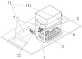
Further, the access device 7 includes a storage component 71 and an absorption component 72, the absorption component 72 is located at the back of the detection table 1, the storage component 71 includes three storage boxes 711 and a supply box 712, the three storage boxes 711 and the supply box 712 are respectively located at the periphery of the absorption component 72, the three storage boxes 711 are used for respectively storing the good FPC flexible printed circuit board detected by the testing component 2, the FPC flexible printed circuit board which is detected by the retesting component 3 and is in abnormal contact with the testing component 2 and the FPC flexible printed circuit board which is in abnormal conduction in a classified manner, and the supply box 712 is used for storing the FPC flexible printed circuit board to be detected.
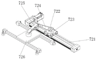
Further, the suction assembly 72 includes a linear guide rail 721, a driving turntable 722 is disposed above the slider of the linear guide rail 721, a suction motor 723 is disposed above the driving turntable 722, an execution mechanical arm 724 is disposed at an output end of the suction motor 723, a suction mechanical arm 725 is connected to a front end of the execution mechanical arm 724, a vacuum chuck 726 is disposed at a front end of the suction mechanical arm 725, the driving turntable 722 and the execution mechanical arm 724, the suction mechanical arm 725 and the vacuum chuck 726 above the driving turntable are carried by the linear guide rail 721 to move, so as to suck and transfer the FPC soft board, wherein, when sucking the FPC, the sucking motor 723 controls the execution mechanical arm 724 and the sucking mechanical arm 725 to extend and extend, so that the vacuum chuck 726 is in contact with the FPC, the FPC soft board is sucked, the execution mechanical arm 724 and the suction mechanical arm 725 are controlled to lift up and retract through the suction motor 723 again, and the FPC soft board is sucked; when the FPC flexible printed circuit board is transferred, the driving turntable 722 drives the vacuum chuck 726 which sucks the FPC flexible printed circuit board to rotate and rotate to the corresponding storage box 711 or supply box 712, and then drives the driving turntable 722 to move through the linear guide 721, so as to move the FPC flexible printed circuit board to the upper side of the corresponding storage box 711, and release the FPC flexible printed circuit board through the vacuum chuck 726.
The working principle is as follows: when in use, firstly, the FPC soft board to be detected is placed in the supply box 712, the drive turntable 722 and the actuating mechanical arm 724, the suction mechanical arm 725 and the vacuum chuck 726 above the drive turntable are carried by the linear guide rail 721 to move, the vacuum chuck 726 is moved to the position above the supply box 712, the suction motor 723 controls the actuating mechanical arm 724 and the suction mechanical arm 725 to extend out and extend, the vacuum chuck 726 extends into the supply box 712 to suck the FPC soft board to be detected, then the actuating mechanical arm 724 and the suction mechanical arm 725 are controlled by the suction motor 723 to lift up and retract, the FPC soft board is moved to the objective table 11 of the detection table 1, and the FPC soft board is parallel to the position right above the objective table 11;
then, a positioning rod 12 arranged on the objective table 11 is matched with a positioning hole on the FPC soft board, so that the FPC soft board can be positioned when being placed on the objective table 11, wherein the positioning rod 12 is positioned between four adjacent test probing holes 13, and after the FPC soft board is positioned, each test probing hole 13 can be matched with each detection point on the FPC soft board, so that the detection effect is ensured, and the testing assembly 2 is further used for detecting the performance of the FPC soft board to be detected;
when the testing component 2 is used for detecting the performance of the FPC soft board, the testing needle template 22 is driven by the testing drive board 21 to move downwards, the performance of the FPC soft board on the detection table 1 is detected, after the testing needle template 22 is contacted with the FPC soft board, the testing needle template 22 stops, the testing drive board 21 continues to descend for a certain distance, at the moment, the testing drive board 21 further compresses the spring 24, the spring 24 is in a compression state, elastic potential energy is accumulated, the testing needle template 22 is pressed, the testing needle template 22 is well contacted with the FPC soft board, the detection result is recorded in a computer, the computer analyzes and judges that the detection performance of the FPC soft board is good or abnormal, and the detection result of the testing component 2 on the FPC soft board is recorded;
then, according to the judgment result, the FPC flexible printed circuit board with good detection performance is removed from the detection device, and is moved to the corresponding storage box 711 by the suction assembly 72 for storage; the FPC soft board with abnormal detection performance is retested for the second time, when retesting, the retesting motor 61 drives the driving gear 62 at the end to rotate, the probe driving teeth 631 on the driving gear 62 are firstly meshed with the upward-moving probe strip-shaped teeth 411, the retesting carrier 41 is driven to move upwards through the upward-moving probe strip-shaped teeth 411, at the moment, the retesting carrier 41 also pushes the mark carrier 51 to move upwards while moving upwards, at the moment, the retesting probe 42 passes through the test probe hole 13 under the driving of the retesting carrier 41 and is contacted with the FPC soft board, the FPC soft board is retested again, the detection result is combined with the result detected by the testing component 2, the abnormal part is judged to belong to the abnormal contact of the testing component 2 or the abnormal conduction of the FPC soft board by a computer, wherein when the retesting result of the abnormal area of the first detection result is good performance, the FPC soft board is shown to belong to the abnormal contact of the testing component 2 when the testing component 2 is detected, when the retest result of the area with good first detection result is abnormal, the contact abnormality of the retest component 3 is indicated when the retest component 3 detects the FPC soft board; when the repeated test result of the first test result abnormal area is abnormal, the FPC soft board is indicated to have abnormal performance;
when retesting the end, carry out corresponding mark to the FPC soft board after retesting through marking component 5: the driving gear 62 continues to rotate, the probe driving teeth 631 rotate to mesh with the downward-moving probe bar teeth 412 and separate from the upward-moving probe bar teeth 411, the probe driving teeth 631 drive the retest support plate 41 to move downward through the downward-moving probe bar teeth 412, and at this time, the marking support plate 51 is static and can start to perform corresponding marking processing on abnormal areas; after the marking is finished, the driving gear 62 continues to rotate until the probe driving teeth 631 are separated from the downward-moving probe bar-shaped teeth 412, the marking driving teeth 632 on one side of the probe driving teeth 631 are meshed with the marking bar-shaped teeth 511, the marking carrier plate 51 is driven to move downward by the marking bar-shaped teeth 511 until the marking driving teeth 632 are separated from the marking bar-shaped teeth 511, the marking carrier plate 51 is contacted with the retesting carrier plate 41 again, the retesting motor 61 stops rotating, the probe driving teeth 631 rotate once and are meshed with the upward-moving probe bar-shaped teeth 411 again, and when retesting is needed next time, the driving gear 62 is driven by the retesting motor 61 again to realize retesting and marking;
the marking process is that a marking stamp is arranged on the marking rod 53, after the marking carrier plate 51 carries all the marking rods 53 and stops moving upwards, the marking rod 53 is positioned in the marking probing hole 14 of the objective table 11, when the computer judges an abnormal result, an operator sends a corresponding marking instruction through the computer, the electromagnetic ejection block 54 at the bottom of the corresponding marking rod 53 is electrified, the marking rod 53 above the electromagnetic ejection block is ejected out of the objective table 11, and the marking rod 53 is contacted with the abnormal position of the FPC soft board and marked; then the linear guide rail 721 carries the driving turntable 722 and the actuating mechanical arm 724, the sucking mechanical arm 725 and the vacuum chuck 726 above the driving turntable to move, so as to suck and transfer the FPC soft board, wherein when the FPC soft board is sucked, the sucking motor 723 controls the actuating mechanical arm 724 and the sucking mechanical arm 725 to extend and stretch, so that the vacuum chuck 726 is in contact with the FPC soft board and sucks the FPC soft board, and the sucking motor 723 controls the actuating mechanical arm 724 and the sucking mechanical arm 725 to lift up and retract again, so as to suck the FPC soft board; when the FPC soft board is transferred, the driving turntable 722 drives the vacuum chuck 726 which absorbs the FPC soft board to rotate and rotate to the direction of the corresponding containing box 711, then the driving turntable 722 is driven to move through the linear guide rail 721, the FPC soft board is moved to the upper part of the corresponding containing box 711, the FPC soft board is released through the vacuum chuck 726, and the performance detection of the FPC soft board is completed.
Although embodiments of the present invention have been shown and described, it will be appreciated by those skilled in the art that changes, modifications, substitutions and alterations can be made in these embodiments without departing from the principles and spirit of the invention, the scope of which is defined in the appended claims and their equivalents.
Claims (6)
1. The utility model provides an intelligent test needle mould equipment for FPC capability test, is including examining test table (1), its characterized in that: the detection table (1) is provided with a test pin die mechanism, and the test pin die mechanism comprises a test component (2) and a retest component (3); when the testing component (2) detects the performance of the FPC soft board to generate inferior products, the retesting component (3) retests the FPC soft board; the retest assembly (3) comprises a retest pin die (4), a marking assembly (5) and a retest drive (6), wherein the retest drive (6) drives the retest pin die (4) and the marking assembly (5) to contact the FPC soft board in an intermittent transmission mode, so that when the retest pin die (4) descends, the marking assembly (5) ascends and marks the FPC soft board; an access device (7) is arranged above the detection table (1), and the access device (7) is used for classifying and stacking the detected FPC soft boards; the retest pin die (4) comprises a plurality of retest support plates (41), a retest probe (42) is arranged above the retest support plates (41), the retest drive (6) is positioned at the bottom of the retest support plates (41), and the marking assembly (5) is positioned above the retest pin die (4); the marking assembly (5) comprises a marking carrier plate (51), the marking carrier plate (51) is positioned above the retest carrier plate (41), a through hole (52) is formed in the marking carrier plate (51), so that the marking carrier plate (51) can move on the retest probe (42), marking rods (53) are arranged on the upper surface of the marking carrier plate (51) and positioned on two sides of the through hole (52), an electromagnetic ejection block (54) is respectively arranged at the bottom of each marking rod (53), and the electromagnetic ejection blocks (54) are matched with the bottoms of the marking rods (53) to mark the FPC soft board; retest drive (6) are including retesting motor (61), retest motor (61) tip is provided with drive gear (62), be provided with umbrella-type tooth (63) on drive gear (62), umbrella-type tooth (63) are including probe drive tooth (631) and mark drive tooth (632), retest support plate (41) are close to one side of retest motor (61) is provided with and moves up probe bar tooth (411) and move down probe bar tooth (412), drive gear (62) are located move up probe bar tooth (411) with move down between probe bar tooth (412), mark support plate (51) one side is provided with mark bar tooth (511), mark bar tooth (511) are located move down one side of probe bar tooth (412).
2. The intelligent test pin die equipment for FPC performance test according to claim 1, characterized by: the testing component (2) comprises a testing driving board (21), a testing needle template (22) is arranged at the bottom of the testing driving board (21), a connecting rod (23) is arranged on the periphery of the bottom of the testing driving board (21) and connected with the testing needle template (22), and a spring (24) is arranged on the periphery of the connecting rod (23); the test drive board (21) drives the test needle template (22) to test the FPC soft board.
3. The intelligent test pin die equipment for FPC performance test according to claim 2, characterized by: the connecting rod (23) is in sliding connection with the test driving plate (21), the connecting rod (23) is fixedly connected with the test needle template (22), and two ends of the spring (24) are respectively fixedly connected with the test driving plate (21) and the test needle template (22); the spring (24) is compressed by the test driving board (21), so that the test pin template (22) is completely contacted with the FPC soft board.
4. The intelligent test pin die equipment for FPC performance test according to claim 1, characterized by: an objective table (11) is arranged in the middle of the upper surface of the detection table (1), and the retest assembly (3) is arranged at the bottom of the objective table (11); a positioning rod (12) is arranged on the upper surface of the object stage (11), and the positioning rod (12) corresponds to a positioning hole in the FPC soft board; a plurality of groups of test probing holes (13) are formed in the objective table (11), the positioning rod (12) is arranged between four adjacent test probing holes (13), and marking probing holes (14) are formed in two sides of each test probing hole (13); the retest probe (42) corresponds to the test probe hole (13) on the object stage (11).
5. The intelligent test pin die equipment for FPC performance test according to claim 1, characterized by: the access device (7) comprises a storage assembly (71) and a suction assembly (72), the suction assembly (72) is located on the back of the detection table (1), the storage assembly (71) comprises three containing boxes (711) and one supply box (712), and the three containing boxes (711) and the one supply box (712) are located on the peripheral side of the suction assembly (72) respectively.
6. The intelligent test pin die equipment for FPC performance test of claim 5, characterized by that: the sucking component (72) comprises a linear guide rail (721), a driving turntable (722) is arranged above a sliding block of the linear guide rail (721), a sucking motor (723) is arranged above the driving turntable (722), an execution mechanical arm (724) is arranged at the output end of the sucking motor (723), a sucking mechanical arm (725) is connected to the front end of the execution mechanical arm (724), and a vacuum sucking disc (726) is arranged at the front end of the sucking mechanical arm (725).
Priority Applications (1)
| Application Number | Priority Date | Filing Date | Title |
|---|---|---|---|
| CN202210552121.1A CN114646868B (en) | 2022-05-21 | 2022-05-21 | Intelligent test needle mold equipment for FPC performance test |
Applications Claiming Priority (1)
| Application Number | Priority Date | Filing Date | Title |
|---|---|---|---|
| CN202210552121.1A CN114646868B (en) | 2022-05-21 | 2022-05-21 | Intelligent test needle mold equipment for FPC performance test |
Publications (2)
| Publication Number | Publication Date |
|---|---|
| CN114646868A CN114646868A (en) | 2022-06-21 |
| CN114646868B true CN114646868B (en) | 2022-08-23 |
Family
ID=81997267
Family Applications (1)
| Application Number | Title | Priority Date | Filing Date |
|---|---|---|---|
| CN202210552121.1A Active CN114646868B (en) | 2022-05-21 | 2022-05-21 | Intelligent test needle mold equipment for FPC performance test |
Country Status (1)
| Country | Link |
|---|---|
| CN (1) | CN114646868B (en) |
Families Citing this family (1)
| Publication number | Priority date | Publication date | Assignee | Title |
|---|---|---|---|---|
| CN116990673B (en) * | 2023-09-26 | 2023-12-12 | 徐州上达芯源半导体技术有限公司 | Electrical testing device for COF packaging |
Family Cites Families (10)
| Publication number | Priority date | Publication date | Assignee | Title |
|---|---|---|---|---|
| US4551675A (en) * | 1983-12-19 | 1985-11-05 | Ncr Corporation | Apparatus for testing printed circuit boards |
| CN208140902U (en) * | 2018-02-01 | 2018-11-23 | 深圳博诚信电子有限公司 | Dedicated test jig is lighted after LED product patch |
| CN108427070A (en) * | 2018-05-22 | 2018-08-21 | 淮安杰鼎唐科技有限公司 | Circuit board detecting equipment and test system |
| CN110082665A (en) * | 2019-04-03 | 2019-08-02 | 厦门工科自动化设备有限公司 | FPC board test device and test method |
| CN212207587U (en) * | 2020-04-17 | 2020-12-22 | 深圳市异科特电子技术检测有限公司 | Device for detecting FPC flexible board |
| CN114062890A (en) * | 2020-08-10 | 2022-02-18 | 杭州旗捷科技有限公司 | Chip test mainboard, chip test equipment and chip test method |
| CN213903721U (en) * | 2020-11-23 | 2021-08-06 | 深圳市大首自动化技术有限公司 | Precise composite FPC electrical measuring machine |
| CN214669444U (en) * | 2021-02-03 | 2021-11-09 | 深圳市联合东创科技有限公司 | Automatic chip tester |
| CN215599309U (en) * | 2021-04-15 | 2022-01-21 | 成都英普飞自动化设备有限公司 | Circuit on-off detection device of flexible circuit board |
| CN113267717B (en) * | 2021-06-11 | 2022-08-23 | 珠海市精实测控技术有限公司 | Circuit board test platform |
-
2022
- 2022-05-21 CN CN202210552121.1A patent/CN114646868B/en active Active
Also Published As
| Publication number | Publication date |
|---|---|
| CN114646868A (en) | 2022-06-21 |
Similar Documents
| Publication | Publication Date | Title |
|---|---|---|
| CN207408551U (en) | The detecting tool of PCBA board | |
| CN104777417A (en) | Modular PCB testing jig | |
| CN112161558B (en) | Automatic detection system for probe stroke | |
| CN114646868B (en) | Intelligent test needle mold equipment for FPC performance test | |
| CN110221193A (en) | A kind of printed circuit board online detection instrument | |
| CN206945907U (en) | A kind of PCBA ATEs | |
| CN210514410U (en) | Probe type electrical measuring machine | |
| CN204556786U (en) | A kind of modular pcb board measurement jig | |
| CN111308316A (en) | Automatic detection equipment of PCBA | |
| CN213903721U (en) | Precise composite FPC electrical measuring machine | |
| CN113253100A (en) | Testing device and detection system | |
| CN208254521U (en) | A kind of automatic conductive film test machine | |
| CN111137025A (en) | Automatic stamp pressing and stamp pressing detection mechanism | |
| CN216117891U (en) | Test fixture of massage armchair PCB board | |
| CN214269277U (en) | Carrying platform mechanism | |
| CN213825981U (en) | Vertical test machine | |
| CN210773981U (en) | Automatic line electric core performance dimension thickness measuring machine | |
| CN217443496U (en) | ICT automatic test mechanism | |
| CN216351054U (en) | Click pad function test fixture | |
| CN215656523U (en) | Circuit board burning and testing integrated machine | |
| CN112845129A (en) | Automatic detection equipment for opening and closing of electric window for automobile main driving | |
| CN219695359U (en) | Automatic dotting mark tester | |
| CN217639395U (en) | Photoelectric sensor synchronism testing device | |
| CN217931326U (en) | Flat TP drawing detection equipment | |
| CN215641652U (en) | FPC high-voltage electrical performance detection equipment |
Legal Events
| Date | Code | Title | Description |
|---|---|---|---|
| PB01 | Publication | ||
| PB01 | Publication | ||
| SE01 | Entry into force of request for substantive examination | ||
| SE01 | Entry into force of request for substantive examination | ||
| GR01 | Patent grant | ||
| GR01 | Patent grant |