CN114622655A - Connecting structure of special-shaped steel pipe concrete column and H-shaped steel beam - Google Patents
Connecting structure of special-shaped steel pipe concrete column and H-shaped steel beam Download PDFInfo
- Publication number
- CN114622655A CN114622655A CN202011461926.2A CN202011461926A CN114622655A CN 114622655 A CN114622655 A CN 114622655A CN 202011461926 A CN202011461926 A CN 202011461926A CN 114622655 A CN114622655 A CN 114622655A
- Authority
- CN
- China
- Prior art keywords
- shaped
- steel
- column
- concrete
- special
- Prior art date
- Legal status (The legal status is an assumption and is not a legal conclusion. Google has not performed a legal analysis and makes no representation as to the accuracy of the status listed.)
- Pending
Links
- 229910000831 Steel Inorganic materials 0.000 title claims abstract description 375
- 239000010959 steel Substances 0.000 title claims abstract description 375
- 239000004567 concrete Substances 0.000 title claims abstract description 110
- 238000003466 welding Methods 0.000 claims abstract description 24
- 206010066054 Dysmorphism Diseases 0.000 claims abstract description 4
- 238000005452 bending Methods 0.000 claims description 2
- 230000000149 penetrating effect Effects 0.000 claims 3
- 238000010276 construction Methods 0.000 abstract description 4
- 238000005192 partition Methods 0.000 description 13
- 230000009286 beneficial effect Effects 0.000 description 2
- 239000011150 reinforced concrete Substances 0.000 description 2
- 230000007547 defect Effects 0.000 description 1
- 238000004519 manufacturing process Methods 0.000 description 1
- 239000000463 material Substances 0.000 description 1
- 238000010008 shearing Methods 0.000 description 1
Images


Classifications
-
- E—FIXED CONSTRUCTIONS
- E04—BUILDING
- E04B—GENERAL BUILDING CONSTRUCTIONS; WALLS, e.g. PARTITIONS; ROOFS; FLOORS; CEILINGS; INSULATION OR OTHER PROTECTION OF BUILDINGS
- E04B1/00—Constructions in general; Structures which are not restricted either to walls, e.g. partitions, or floors or ceilings or roofs
- E04B1/38—Connections for building structures in general
- E04B1/58—Connections for building structures in general of bar-shaped building elements
-
- E—FIXED CONSTRUCTIONS
- E04—BUILDING
- E04B—GENERAL BUILDING CONSTRUCTIONS; WALLS, e.g. PARTITIONS; ROOFS; FLOORS; CEILINGS; INSULATION OR OTHER PROTECTION OF BUILDINGS
- E04B1/00—Constructions in general; Structures which are not restricted either to walls, e.g. partitions, or floors or ceilings or roofs
- E04B1/18—Structures comprising elongated load-supporting parts, e.g. columns, girders, skeletons
- E04B1/185—Connections not covered by E04B1/21 and E04B1/2403, e.g. connections between structural parts of different material
-
- E—FIXED CONSTRUCTIONS
- E04—BUILDING
- E04G—SCAFFOLDING; FORMS; SHUTTERING; BUILDING IMPLEMENTS OR AIDS, OR THEIR USE; HANDLING BUILDING MATERIALS ON THE SITE; REPAIRING, BREAKING-UP OR OTHER WORK ON EXISTING BUILDINGS
- E04G21/00—Preparing, conveying, or working-up building materials or building elements in situ; Other devices or measures for constructional work
- E04G21/02—Conveying or working-up concrete or similar masses able to be heaped or cast
Landscapes
- Engineering & Computer Science (AREA)
- Architecture (AREA)
- Civil Engineering (AREA)
- Structural Engineering (AREA)
- Physics & Mathematics (AREA)
- Electromagnetism (AREA)
- Mechanical Engineering (AREA)
- Joining Of Building Structures In Genera (AREA)
Abstract
Dysmorphism steel core concrete column and H shape girder steel connection structure, it includes: an upper column and a lower column of the special-shaped steel pipe concrete column, a steel structure node area and an H-shaped steel beam; the steel structure node domain is a steel structure member which is formed by a plurality of H-shaped through steel beams and has the same shape as the cross section of the special-shaped concrete filled steel tube column; the upper column and the lower column of the special-shaped concrete filled steel tube column are respectively welded on an upper flange and a lower flange of the steel structure node domain, the upper flange and the lower flange of the H-shaped steel beam are respectively welded with the upper flange and the lower flange of the steel structure node domain, and the web of the H-shaped steel beam and the web of the steel structure node domain are connected through a connecting plate and a bolt. The invention has the advantages of less on-site welding work, no influence on concrete pouring in the steel tube, high construction speed, no protruding cylindrical surface of the node, reliable node connection and the like.
Description
Technical Field
The invention relates to a special-shaped steel pipe concrete structure, in particular to a connecting structure of a special-shaped steel pipe concrete column and an H-shaped steel beam.
Background
The special-shaped steel pipe concrete structure is used as a novel combined structure, has the advantages of high bearing capacity, good plasticity and toughness, superior anti-seismic performance and the like of the steel pipe concrete column, and has numerous advantages of the special-shaped reinforced concrete column structure: the column corner is avoided, the layout is flexible, and the aesthetic requirements of building space are met; higher area utilization; energy and land are saved, and the sustainable development requirement is met; and overcomes the defect of poor anti-seismic performance of the reinforced concrete special-shaped column structure. At present, along with the longing and pursuing of people to humanized living environment, the special-shaped steel tube concrete structure has wide application prospect in the construction of small high-rise and high-rise residential buildings along with the rapid development of material civilization.
The steel beam and the special-shaped steel pipe concrete column component are connected through the node to form a structural stress system, and the selection of the node form has direct influence on structural integrity, reliability and design and construction of accessory components. The research on the connecting nodes of the special-shaped steel pipe concrete beam column mainly focuses on the outer partition plate type nodes, the inner partition plate type nodes, the side plate connecting nodes and the like. The outer partition plate type node influences the service function of the building due to the protruding cylindrical surface of the outer partition plate, the inner partition plate type node influences the pouring quality of concrete due to the fact that the inner partition plate is located in the pipe wall, the side plate connecting node is connected with the steel beam through the side plate connecting plate in a welded mode, welding workload is large, and the outer partition plate type node is not suitable for being connected with the H-shaped steel beam.
Disclosure of Invention
The invention aims to provide a connecting structure of a special-shaped steel pipe concrete column and an H-shaped steel beam, and aims to solve the problems that the existing special-shaped steel pipe concrete outer partition type node, inner partition type node and side plate connecting node protrude the column surface, concrete pouring is affected, and welding workload is large.
In order to achieve the purpose, the technical scheme of the invention is as follows:
dysmorphism steel core concrete column and H shape girder steel connection structure, it includes: an upper column and a lower column of the special-shaped steel pipe concrete column, a steel structure node area and an H-shaped steel beam; the steel structure node domain is a steel structure member which is formed by a plurality of H-shaped through steel beams and has the same shape with the cross section of the special-shaped steel tube concrete column; the upper column and the lower column of the special-shaped concrete filled steel tube column are respectively welded on an upper flange and a lower flange of the steel structure node domain, the upper flange and the lower flange of the H-shaped steel beam are respectively welded with the upper flange and the lower flange of the steel structure node domain, and the web of the H-shaped steel beam and the web of the steel structure node domain are connected through a connecting plate and a bolt.
Preferably, a plurality of transverse stiffening ribs are welded between upper and lower flanges at two sides of the H-shaped through steel beam in the steel structure node area; a plurality of grouting holes are formed in upper and lower flanges between the transverse stiffening ribs of the H-shaped through steel beam; the upper and lower flanges of the H-shaped through steel beam are as wide as the upper and lower column limbs of the special-shaped concrete-filled steel tube column; the length of the H-shaped through steel beam is larger than that of the special-shaped concrete filled steel tube column limb, so that the H-shaped through steel beam extends out of the special-shaped concrete filled steel tube column limb.
Preferably, the cross sectional shape of dysmorphism steel core concrete column is L shape, T shape or cross, and is corresponding, the shape of steel construction node field is L shape, T shape or cross.
Preferably, the cross-sectional shape of the special-shaped concrete filled steel tube column and the shape of the steel structure node area are both L-shaped; the L-shaped special-shaped steel pipe concrete column comprises an L-shaped steel pipe cavity and concrete poured in the steel pipe cavity, the L-shaped steel pipe cavity is formed by welding a rectangular steel pipe and a U-shaped steel plate, and the opening end of the U-shaped steel plate is fixedly connected with one side end of a long-edge wall plate of the rectangular steel pipe; or the L-shaped steel pipe cavity is formed by welding three L-shaped steel plates.
Preferably, the steel structure node domain is L-shaped and is composed of at least two H-shaped through steel beams which are mutually connected in a cross mode, and the end portions of the H-shaped through steel beams are respectively connected with the H-shaped steel beams.
Preferably, the end portions of the H-shaped through steel beams cross-connected with each other pass through the other H-shaped through steel beam, and correspondingly, the end portions of the two ends of the H-shaped through steel beam are respectively connected with the H-shaped steel beams.
Preferably, the cross section shape of the special-shaped concrete filled steel tube column and the shape of the steel structure node area are both cross-shaped; the cross-shaped special-shaped steel pipe concrete column comprises a cross-shaped steel pipe cavity and concrete poured in the steel pipe cavity, wherein the cross-shaped steel pipe cavity is formed by a rectangular steel pipe and two U-shaped steel plates welded in the center of the two side faces of the rectangular steel pipe, or is formed by two L-shaped steel plates welded into the rectangular steel pipe and two U-shaped steel plates welded in the center of the two side faces of the rectangular steel pipe.
Preferably, the cross section shape of the special-shaped concrete filled steel tube column and the shape of the steel structure node area are both cross-shaped; the cross-shaped steel structure node domain is formed by mutually and crossly connecting at least two H-shaped through steel beams into a cross shape, and the end parts of the H-shaped through steel beams are respectively connected with the H-shaped steel beams.
Preferably, the cross section shape of the special-shaped steel tube concrete column and the cross section shape of the steel structure node area are both T-shaped; the T-shaped special-shaped steel pipe concrete column comprises a T-shaped steel pipe cavity and concrete poured in the steel pipe cavity, wherein the T-shaped steel pipe cavity is composed of a rectangular steel pipe and two U-shaped steel plates welded on two side faces of one end of the rectangular steel pipe, or is composed of an L-shaped steel pipe formed by welding two L-shaped steel plates and a U-shaped steel plate welded on the lower portion of one side face of the L-shaped steel pipe.
Preferably, the cross-sectional shape of the special-shaped concrete filled steel tube column and the shape of the steel structure node area are both T-shaped; the T-shaped steel structure node domain is formed by intersecting at least two H-shaped through steel beams, and the end parts of two ends of each H-shaped through steel beam are respectively connected with the H-shaped steel beams.
Preferably, the end part of one H-shaped through steel beam at the intersection passes through the middle part of the other opposite H-shaped through steel beam, and correspondingly, the end parts of the two ends of the H-shaped through steel beam are respectively connected with the H-shaped steel beams.
Preferably, the rectangular steel pipe in the special-shaped concrete filled steel pipe column is formed by welding two L-shaped steel plates or is formed by bending a rectangular steel plate and then welding.
The invention has the beneficial effects that:
compared with the traditional outer partition plate type node, the technical scheme of the invention has the advantages that the node does not protrude out of the cylindrical surface, the problem that the concrete pouring quality of the column section between the upper partition plate and the lower partition plate of the traditional inner partition plate type node is difficult to guarantee is solved, and meanwhile, compared with the traditional side plate connecting node, the node of the technical scheme has better stress performance in all directions and more reliable connection.
The node domain adopting the structural form of the invention can be connected with the H-shaped steel beam in any direction at any position of the node domain by combining the arrangement of the transverse stiffening ribs of the node domain, and is not only connected with the H-shaped steel beam in the column limb direction of the special-shaped column, which is an advantage that the traditional scheme does not have.
A plurality of grouting holes are formed in the upper flange and the lower flange of the H-shaped steel in the node area, and when concrete at the column end is not tightly poured, the concrete can be poured inwards through the grouting holes, so that the tight pouring of the concrete is ensured; meanwhile, the grouting holes are formed in the upper flange and the lower flange of the H-shaped steel in the node area, so that the stress of the structure is hardly influenced; the traditional treatment mode is to open a hole on the column wall of the special-shaped steel column and then perform grouting, and then repair welding the hole by using a steel plate, so that the integrity of the special-shaped steel column is damaged, and the on-site welding workload is increased.
By adopting the node domain, the rigidity of the node domain is high, the vertical shearing force of the beam end of the steel beam is favorably and effectively and uniformly transferred to the steel pipe and the concrete of the special-shaped steel pipe column, and the cooperative work of the steel pipe and the concrete in the pipe is ensured.
The steel pipe cavity dividing mode and the special-shaped steel pipe splicing mode adopted by the invention can ensure the rigidity of the internal corner part of the steel pipe, and have convenient welding, few welding seams and no mutual influence among the welding seams, thereby ensuring the welding quality of the steel pipe and the bearing capacity of the column.
The invention divides the joint into three components of the special-shaped steel pipe concrete upper column and lower column, the H-shaped steel beam and the steel structure joint domain through the joint domain, each component unit can be prefabricated and processed independently, and finally, the components are welded and integrated, thereby being beneficial to accelerating the production and processing speed of the components.
According to the invention, the connection of the H-shaped steel beam and the steel structure node area is combined by adopting bolt welding, the upper flange and the lower flange of the H-shaped steel beam are respectively welded with the upper flange and the lower flange of the H-shaped through steel beam in the steel structure node area, and the web plate of the H-shaped steel beam is connected with the web plate of the H-shaped through steel beam in the steel structure node area through bolts, so that the field welding workload is reduced, and the connection reliability is ensured.
Drawings
FIG. 1 is a perspective view of example 1 (L-shaped) of the present invention;
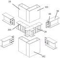
FIG. 2 is an exploded perspective view of embodiment 1 of the present invention;
fig. 3 is a perspective view of a profile concrete filled steel tube column according to example 1 of the present invention.
Fig. 4 is an exploded perspective view of one of the structural forms of the deformed concrete filled steel tube column according to embodiment 1 of the present invention;
fig. 5 is an exploded perspective view of a second exploded perspective view of a beam concrete filled steel tube column structure according to example 1 of the present invention;
FIG. 6 is an exploded perspective view showing one of the structural forms of the node domain of the steel structure in example 1 of the present invention;
FIG. 7 is an exploded perspective view showing a second structural form of the node region of the steel structure in example 1 of the present invention;
FIG. 8 is an exploded perspective view of example 2 (cross shape) of the present invention;
fig. 9 is a perspective view of a deformed concrete filled steel tube column according to example 2 of the present invention;
fig. 10 is an exploded perspective view of one of the structural forms of the deformed concrete filled steel tube column according to embodiment 2 of the present invention;
FIG. 11 is a two-dimensional exploded view showing the structural form of a beam column made of a beam-shaped concrete filled steel tube according to example 2 of the present invention;
FIG. 12 is an exploded perspective view of example 3 (T-shape) of the present invention;
FIG. 13 is a two-dimensional exploded view showing the structural configuration of the node domain of the steel structure in example 3 of the present invention;
fig. 14 is a perspective view of a deformed concrete filled steel tube column according to example 3 of the present invention;
fig. 15 is an exploded perspective view of one of the structural forms of the deformed concrete filled steel tube column according to embodiment 3 of the present invention;
fig. 16 is an exploded perspective view of a second structural form of a beam concrete filled steel tube column according to example 3 of the present invention.
Detailed Description
Referring to fig. 1 and 2, the connection structure of the special-shaped steel pipe concrete column and the H-shaped steel beam includes: an upper column 101 and a lower column 102 of the special-shaped steel pipe concrete column 10, a steel structure node area 20 and an H-shaped steel beam 30; the steel structure node area is 20, and a steel structural part with the same shape as the cross section of the special-shaped steel tube concrete column 10 is formed by a plurality of H-shaped through steel beams 201; the upper column 101 and the lower column 102 of the special-shaped concrete filled steel tube column 10 are respectively welded to the upper flange and the lower flange of the H-shaped through steel beam 201 of the steel structure node domain 20, the upper flange and the lower flange of the H-shaped steel beam 30 are respectively welded with the upper flange and the lower flange of the H-shaped through steel beam 201 of the steel structure node domain 20, and the web of the H-shaped steel beam 30 and the web of the H-shaped through steel beam 201 of the steel structure node domain 20 are connected through a connecting plate 40 and a bolt.
Referring to fig. 1, the section of the special-shaped steel pipe concrete column 10 is L-shaped, T-shaped or cross-shaped, and correspondingly, the section of the steel structure node area 20 is L-shaped, T-shaped or cross-shaped.
Preferably, a plurality of transverse stiffening ribs 202 are welded between the upper and lower flanges at two sides of the H-shaped through steel beam 201; a plurality of grouting holes 203 are formed on the upper and lower flanges between the transverse stiffening ribs 202 of the H-shaped through steel beam 201; the upper and lower flanges of the H-shaped through steel beam 201 are as wide as the upper column 101 and the lower column 102 of the special-shaped concrete filled steel tube column 10; the length of the H-shaped through steel beam 201 is larger than that of the special-shaped concrete filled steel tube column 10, so that the H-shaped through steel beam extends out of the special-shaped concrete filled steel tube column 10.
Referring to fig. 3 and 4, the L-shaped special-shaped steel tube concrete column (taking the column 101 as an example) includes an L-shaped steel tube cavity and concrete poured in the steel tube cavity, the L-shaped steel tube cavity is formed by welding a rectangular steel tube 1011 and a U-shaped steel plate 1012, and an open end of the U-shaped steel plate 1012 is fixedly connected with one side end of a long-side wall plate of the rectangular steel tube 1011; or three L-shaped steel plates 1013 welded together as shown in fig. 5.
Referring to fig. 6, in this embodiment, the special-shaped steel tube concrete column 10 and the steel structure node domain 20 in the connection structure of the special-shaped steel tube concrete column and the H-shaped steel beam are both L-shaped, wherein the steel structure node domain 20 is composed of two H-shaped through steel beams 201, one H-shaped through steel beam at the intersection of the two H-shaped through steel beams 201 extends out of the other H-shaped through steel beam, and correspondingly, the ends of the H-shaped through steel beams are respectively connected with the H-shaped steel beams 30.
Referring to fig. 7, in this embodiment, the special-shaped steel tube concrete column 10 and the steel structure node region 20 in the connection structure of the special-shaped steel tube concrete column and the H-shaped steel beam are both L-shaped, wherein the steel structure node region 20 is composed of two H-shaped through steel beams 201, ends of the two H-shaped through steel beams at the intersection of the two H-shaped through steel beams 201 respectively extend out of the other H-shaped through steel beam, and correspondingly, ends of two ends of each H-shaped through steel beam are respectively connected to the H-shaped steel beams 30.
Referring to fig. 8, in this embodiment, the special-shaped steel tube concrete column 10 and the steel structure node domain 20 in the connection structure of the special-shaped steel tube concrete column and the H-shaped steel beam are both cross-shaped, wherein the steel structure node domain 20 is composed of two H-shaped through steel beams 201, the two H-shaped through steel beams 201 are cross-connected with each other, and correspondingly, the ends of the H-shaped through steel beams are respectively connected with the H-shaped steel beams 30.
Referring to fig. 9 and 10, the cross-shaped special-shaped concrete filled steel tube column (taking the column 101 as an example) includes a cross-shaped steel tube cavity and concrete poured in the steel tube cavity, and the cross-shaped steel tube cavity is composed of a rectangular steel tube 1011 and two U-shaped steel plates 1012 welded in the centers of two side surfaces of the rectangular steel tube.
Referring to fig. 11, in the cross-shaped special-shaped steel pipe concrete column (the column 101 is taken as an example), a rectangular steel pipe 1011 is formed by welding two L-shaped steel plates 1013.
Referring to fig. 12, in the present embodiment, the special-shaped steel tube concrete column 10 and the steel structure node area 20 in the connection structure of the special-shaped steel tube concrete column and the H-shaped steel beam are both T-shaped, wherein the steel structure node area 20 is composed of two H-shaped through steel beams 201.
Referring to fig. 13, in the present embodiment, in the special-shaped concrete filled steel tubular column (taking the column 101 as an example), an end of one H-shaped through steel beam at an intersection of two H-shaped through steel beams 201 in the steel structure node domain 20 extends out of a middle portion of the other H-shaped through steel beam, and accordingly, two end portions of each H-shaped through steel beam are respectively connected to the H-shaped steel beams 30.
Referring to fig. 14 and 15, the T-shaped special-shaped concrete filled steel tube column (taking the column 101 as an example) includes a T-shaped steel tube cavity and concrete poured in the steel tube cavity, and the T-shaped steel tube cavity is composed of a rectangular steel tube 1011 and two U-shaped steel plates 1012 welded to one end of two side surfaces of the rectangular steel tube 1011.
Referring to fig. 16, in the T-shaped special-shaped steel pipe concrete column (the above column 101 is taken as an example), a rectangular steel pipe 1011 is formed by welding two L-shaped steel plates 1013.
Claims (12)
1. Dysmorphism steel core concrete column and H shape girder steel connection structure, its characterized in that includes: an upper column and a lower column of the special-shaped steel pipe concrete column, a steel structure node area and an H-shaped steel beam; the steel structure node domain is a steel structure member which is formed by a plurality of H-shaped through steel beams and has the same shape with the cross section of the special-shaped steel tube concrete column; the upper column and the lower column of the special-shaped concrete filled steel tube column are respectively welded on an upper flange and a lower flange of the steel structure node domain, the upper flange and the lower flange of the H-shaped steel beam are respectively welded with the upper flange and the lower flange of the steel structure node domain, and the web of the H-shaped steel beam and the web of the steel structure node domain are connected through a connecting plate and a bolt.
2. The connection structure of the special-shaped steel pipe concrete column and the H-shaped steel beam as claimed in claim 1, wherein a plurality of transverse stiffening ribs are welded between upper and lower flanges at two sides of the H-shaped through steel beam in the steel structure joint area; a plurality of grouting holes are formed in upper and lower flanges between the transverse stiffening ribs of the H-shaped through steel beam; the upper and lower flanges of the H-shaped through steel beam are as wide as the upper and lower column limbs of the special-shaped concrete-filled steel tube column; the length of the H-shaped through steel beam is larger than that of the special-shaped concrete filled steel tube column limb, so that the H-shaped through steel beam extends out of the special-shaped concrete filled steel tube column limb.
3. The structure for connecting a deformed concrete filled steel tube column and an H-shaped steel beam according to claim 1 or 2, wherein the cross-sectional shape of the deformed concrete filled steel tube column is L-shaped, T-shaped or cross-shaped, and correspondingly, the shape of the steel structure node area is L-shaped, T-shaped or cross-shaped.
4. The structure for connecting a deformed concrete filled steel tube column and an H-shaped steel beam according to claim 1 or 2, wherein the cross-sectional shape of the deformed concrete filled steel tube column and the shape of the steel structure joint region are both L-shaped; the L-shaped special-shaped steel pipe concrete column comprises an L-shaped steel pipe cavity and concrete poured in the steel pipe cavity, the L-shaped steel pipe cavity is formed by welding a rectangular steel pipe and a U-shaped steel plate, and the open end of the U-shaped steel plate is fixedly connected with one side end of a long-edge wall plate of the rectangular steel pipe; or the L-shaped steel pipe cavity is formed by welding three L-shaped steel plates.
5. The connection structure of the beam-shaped steel pipe concrete column and the H-shaped steel beam as claimed in claim 1, 2, 3 or 4, wherein the shape of the steel structure node region is L-shaped and is composed of at least two H-shaped through steel beams which are connected with each other in a cross manner, and the ends of the H-shaped through steel beams are respectively connected with the H-shaped steel beams.
6. The structure for connecting a beam-shaped concrete-filled steel tube column to an H-shaped steel beam according to claim 5, wherein the end portions of the H-shaped through-beams cross-connected to each other pass through the opposite other H-shaped through-beam, and the H-shaped through-beams are connected to the end portions of both ends of the H-shaped through-beams, respectively.
7. The structure for connecting a deformed concrete filled steel tube column and an H-shaped steel beam according to claim 1, 2 or 3, wherein the cross-sectional shape of the deformed concrete filled steel tube column and the shape of the steel structure joint area are both cross-shaped; the cross-shaped special-shaped steel pipe concrete column comprises a cross-shaped steel pipe cavity and concrete poured in the steel pipe cavity, wherein the cross-shaped steel pipe cavity is formed by a rectangular steel pipe and two U-shaped steel plates welded in the center of the two side faces of the rectangular steel pipe, or is formed by two L-shaped steel plates welded into the rectangular steel pipe and two U-shaped steel plates welded in the center of the two side faces of the rectangular steel pipe.
8. The structure for connecting a deformed concrete filled steel tube column and an H-shaped steel beam according to claim 1, 2, 3 or 7, wherein the cross-sectional shape of the deformed concrete filled steel tube column and the shape of the steel structure joint area are both cross-shaped; the cross-shaped steel structure node domain is formed by mutually and crossly connecting at least two H-shaped through steel beams into a cross shape, and the end parts of the H-shaped through steel beams are respectively connected with the H-shaped steel beams.
9. The structure for connecting a deformed concrete filled steel tube column and an H-shaped steel beam according to claim 1 or 2, wherein the cross-sectional shape of the deformed concrete filled steel tube column and the cross-sectional shape of the steel structure node region are both T-shaped; the T-shaped special-shaped steel pipe concrete column comprises a T-shaped steel pipe cavity and concrete poured in the steel pipe cavity, wherein the T-shaped steel pipe cavity is formed by a rectangular steel pipe and two U-shaped steel plates welded on two side faces of one end of the rectangular steel pipe, or is formed by an L-shaped steel pipe formed by welding two L-shaped steel plates and a U-shaped steel plate welded on the lower portion of one side face of the L-shaped steel pipe.
10. The structure for connecting a deformed concrete filled steel tube column and an H-shaped steel beam according to claim 1, 2, 3 or 9, wherein the cross-sectional shape of the deformed concrete filled steel tube column and the shape of the steel structure joint region are both T-shaped; the T-shaped steel structure node domain is formed by intersecting at least two H-shaped through steel beams, and the end parts of two ends of each H-shaped through steel beam are respectively connected with the H-shaped steel beams.
11. The structure for connecting a profile steel pipe concrete column and an H-shaped steel beam according to claim 10, wherein one end of one H-shaped penetrating steel beam at the intersection passes through the middle of the other H-shaped penetrating steel beam, and the two end portions of the H-shaped penetrating steel beam are respectively connected to the H-shaped steel beams.
12. The structure for connecting a special-shaped concrete-filled steel tube column and an H-shaped steel beam according to claim 4, 7 or 9, wherein the rectangular steel tube in the special-shaped concrete-filled steel tube column is formed by welding two L-shaped steel plates, or is formed by bending and welding a rectangular steel plate.
Priority Applications (1)
| Application Number | Priority Date | Filing Date | Title |
|---|---|---|---|
| CN202011461926.2A CN114622655A (en) | 2020-12-11 | 2020-12-11 | Connecting structure of special-shaped steel pipe concrete column and H-shaped steel beam |
Applications Claiming Priority (1)
| Application Number | Priority Date | Filing Date | Title |
|---|---|---|---|
| CN202011461926.2A CN114622655A (en) | 2020-12-11 | 2020-12-11 | Connecting structure of special-shaped steel pipe concrete column and H-shaped steel beam |
Publications (1)
| Publication Number | Publication Date |
|---|---|
| CN114622655A true CN114622655A (en) | 2022-06-14 |
Family
ID=81895783
Family Applications (1)
| Application Number | Title | Priority Date | Filing Date |
|---|---|---|---|
| CN202011461926.2A Pending CN114622655A (en) | 2020-12-11 | 2020-12-11 | Connecting structure of special-shaped steel pipe concrete column and H-shaped steel beam |
Country Status (1)
| Country | Link |
|---|---|
| CN (1) | CN114622655A (en) |
Cited By (1)
| Publication number | Priority date | Publication date | Assignee | Title |
|---|---|---|---|---|
| CN114961391A (en) * | 2022-06-27 | 2022-08-30 | 重庆大学 | Assembled node of steel pipe concrete special-shaped column and H-shaped steel beam |
Citations (14)
| Publication number | Priority date | Publication date | Assignee | Title |
|---|---|---|---|---|
| JPH10280542A (en) * | 1997-03-31 | 1998-10-20 | Ando Corp | Joint construction between reinforced concrete column and steel framed beam |
| CN202202415U (en) * | 2011-07-22 | 2012-04-25 | 西安建筑科技大学 | Side node of rectangular steel pipe concrete special-shaped column and steel beam framework |
| CN202202413U (en) * | 2011-07-22 | 2012-04-25 | 西安建筑科技大学 | Rectangular steel tube concrete special-shaped column and steel beam frame corner node |
| CN202202412U (en) * | 2011-07-22 | 2012-04-25 | 西安建筑科技大学 | Rectangular steel pipe concrete special-shaped column-steel beam framework middle node |
| CN104912206A (en) * | 2015-05-29 | 2015-09-16 | 重庆大学 | Special-shaped concrete filled steel tube column-I-shaped steal beam framework node |
| CN105133729A (en) * | 2015-08-05 | 2015-12-09 | 北京建工华创科技发展股份有限公司 | Abnormity beam column steel frame with sandwich board and construction method thereof |
| CN206360087U (en) * | 2016-11-24 | 2017-07-28 | 重庆市中科大业建筑科技有限公司 | A kind of clod wash multi-cavity steel tube concrete Special-Shaped Column and the rigid joint of H profile steel beam |
| CN108193771A (en) * | 2018-03-20 | 2018-06-22 | 辽宁工程技术大学 | A kind of assembling rectangular steel-tube concrete column-girder steel partition board perforation node |
| CN109881789A (en) * | 2019-03-28 | 2019-06-14 | 华南理工大学 | A kind of dismountable girder steel-steel core concrete column punching connecting node |
| CN209523385U (en) * | 2018-08-03 | 2019-10-22 | 北京和筑科技有限公司 | Special-shaped column assembly and beam-column connection structure |
| CN211172362U (en) * | 2018-12-10 | 2020-08-04 | 山东建筑大学 | Hoop reinforced square steel tube concrete combined special-shaped beam column-steel beam connecting joint |
| CN211572251U (en) * | 2019-10-15 | 2020-09-25 | 北京和筑科技有限公司 | H-shaped steel and cold-formed steel plate component combined concrete filled steel tube special-shaped column |
| JP2020165132A (en) * | 2019-03-28 | 2020-10-08 | 株式会社フジタ | Column-beam joint structure and construction method of building having column-beam joint structure |
| CN211774541U (en) * | 2019-11-30 | 2020-10-27 | 山东科技大学 | Assembled T-shaped special-shaped column-steel beam full-bolt rigid node structure |
-
2020
- 2020-12-11 CN CN202011461926.2A patent/CN114622655A/en active Pending
Patent Citations (14)
| Publication number | Priority date | Publication date | Assignee | Title |
|---|---|---|---|---|
| JPH10280542A (en) * | 1997-03-31 | 1998-10-20 | Ando Corp | Joint construction between reinforced concrete column and steel framed beam |
| CN202202415U (en) * | 2011-07-22 | 2012-04-25 | 西安建筑科技大学 | Side node of rectangular steel pipe concrete special-shaped column and steel beam framework |
| CN202202413U (en) * | 2011-07-22 | 2012-04-25 | 西安建筑科技大学 | Rectangular steel tube concrete special-shaped column and steel beam frame corner node |
| CN202202412U (en) * | 2011-07-22 | 2012-04-25 | 西安建筑科技大学 | Rectangular steel pipe concrete special-shaped column-steel beam framework middle node |
| CN104912206A (en) * | 2015-05-29 | 2015-09-16 | 重庆大学 | Special-shaped concrete filled steel tube column-I-shaped steal beam framework node |
| CN105133729A (en) * | 2015-08-05 | 2015-12-09 | 北京建工华创科技发展股份有限公司 | Abnormity beam column steel frame with sandwich board and construction method thereof |
| CN206360087U (en) * | 2016-11-24 | 2017-07-28 | 重庆市中科大业建筑科技有限公司 | A kind of clod wash multi-cavity steel tube concrete Special-Shaped Column and the rigid joint of H profile steel beam |
| CN108193771A (en) * | 2018-03-20 | 2018-06-22 | 辽宁工程技术大学 | A kind of assembling rectangular steel-tube concrete column-girder steel partition board perforation node |
| CN209523385U (en) * | 2018-08-03 | 2019-10-22 | 北京和筑科技有限公司 | Special-shaped column assembly and beam-column connection structure |
| CN211172362U (en) * | 2018-12-10 | 2020-08-04 | 山东建筑大学 | Hoop reinforced square steel tube concrete combined special-shaped beam column-steel beam connecting joint |
| CN109881789A (en) * | 2019-03-28 | 2019-06-14 | 华南理工大学 | A kind of dismountable girder steel-steel core concrete column punching connecting node |
| JP2020165132A (en) * | 2019-03-28 | 2020-10-08 | 株式会社フジタ | Column-beam joint structure and construction method of building having column-beam joint structure |
| CN211572251U (en) * | 2019-10-15 | 2020-09-25 | 北京和筑科技有限公司 | H-shaped steel and cold-formed steel plate component combined concrete filled steel tube special-shaped column |
| CN211774541U (en) * | 2019-11-30 | 2020-10-27 | 山东科技大学 | Assembled T-shaped special-shaped column-steel beam full-bolt rigid node structure |
Cited By (2)
| Publication number | Priority date | Publication date | Assignee | Title |
|---|---|---|---|---|
| CN114961391A (en) * | 2022-06-27 | 2022-08-30 | 重庆大学 | Assembled node of steel pipe concrete special-shaped column and H-shaped steel beam |
| CN114961391B (en) * | 2022-06-27 | 2024-10-18 | 重庆大学 | Assembled node of steel pipe concrete special-shaped column and H-shaped steel beam |
Similar Documents
| Publication | Publication Date | Title |
|---|---|---|
| CN107476446B (en) | Banded enhancement mode node that H shaped steel roof beam and wide steel core concrete column minor face are connected | |
| KR102079008B1 (en) | E-z connecting structure for beam and column wherein the end-moment and bending resistibility are reinforced | |
| CN111962952B (en) | Steel pipe concrete column-H-shaped steel beam-steel support-pi-shaped connecting piece combined type middle column bottom node and manufacturing method | |
| WO2022057642A1 (en) | Steel special-shaped column with corrugated plates for connection | |
| KR101174548B1 (en) | Column system of concrete filled steel tube | |
| CN213297357U (en) | Concrete column-H steel beam-steel support-pi combined center pillar middle node | |
| CN213773847U (en) | Cross-shaped steel pipe concrete column and steel beam connecting node structure | |
| CN111962949B (en) | Concrete filled steel tube column-H-shaped steel beam-steel support-pi-shaped connecting piece combined type middle column middle node and manufacturing method | |
| CN105839793A (en) | Rigid connection joint of multi-cavity concrete-filled steel tube composite column and steel beam as well as assembly method | |
| CN110284605A (en) | Assembly type concrete filled steel tube combined column joint area connecting structure | |
| CN210947142U (en) | Assembled concrete structure post roof beam connecting steel node | |
| CN216713336U (en) | Double-limb spliced beam and steel pipe column and double-limb spliced beam assembly type beam column joint | |
| CN111119336A (en) | Y-shaped vertical face intersection conversion node formed by welding box-type steel pipes and application | |
| CN114622655A (en) | Connecting structure of special-shaped steel pipe concrete column and H-shaped steel beam | |
| CN105863056A (en) | Double-side-plate screw bolt node for beam column and assembly method | |
| CN112160418A (en) | Anti special-shaped post frame construction system of side of assembled buckled plate | |
| CN112302167A (en) | Assembled steel construction dysmorphism post frame construction system | |
| WO2023202490A1 (en) | Built-in laced-type lattice column double steel plate shear wall having wall-beam joint region | |
| CN107327029B (en) | Steel pipe concrete column-girder steel assembled space node | |
| CN110700422A (en) | DK type space intersection node formed by welding box type steel pipes and application | |
| CN113565207B (en) | Assembly type beam-column joint structure and construction method | |
| CN213773848U (en) | T-shaped concrete filled steel tube column and steel beam connecting node structure | |
| CN113605541A (en) | Outer ring type beam column rigid connection node | |
| CN216973760U (en) | Outer ring type beam column rigid connection node | |
| CN213773849U (en) | L-shaped concrete filled steel tube column and steel beam bolted welding connection node structure |
Legal Events
| Date | Code | Title | Description |
|---|---|---|---|
| PB01 | Publication | ||
| PB01 | Publication | ||
| SE01 | Entry into force of request for substantive examination | ||
| SE01 | Entry into force of request for substantive examination |