CN113605541A - Outer ring type beam column rigid connection node - Google Patents

Outer ring type beam column rigid connection node Download PDF

Info

Publication number
CN113605541A
CN113605541A CN202110868099.7A CN202110868099A CN113605541A CN 113605541 A CN113605541 A CN 113605541A CN 202110868099 A CN202110868099 A CN 202110868099A CN 113605541 A CN113605541 A CN 113605541A
Authority
CN
China
Prior art keywords
outer ring
column
ring type
connection node
rectangular
Prior art date
Legal status (The legal status is an assumption and is not a legal conclusion. Google has not performed a legal analysis and makes no representation as to the accuracy of the status listed.)
Pending
Application number
CN202110868099.7A
Other languages
Chinese (zh)
Inventor
吴宏磊
刘兴能
刘博�
沈倩
张瑶
Current Assignee (The listed assignees may be inaccurate. Google has not performed a legal analysis and makes no representation or warranty as to the accuracy of the list.)
Architecture Design and Research Institute of Tongji University Group Co Ltd
Original Assignee
Architecture Design and Research Institute of Tongji University Group Co Ltd
Priority date (The priority date is an assumption and is not a legal conclusion. Google has not performed a legal analysis and makes no representation as to the accuracy of the date listed.)
Filing date
Publication date
Application filed by Architecture Design and Research Institute of Tongji University Group Co Ltd filed Critical Architecture Design and Research Institute of Tongji University Group Co Ltd
Priority to CN202110868099.7A priority Critical patent/CN113605541A/en
Publication of CN113605541A publication Critical patent/CN113605541A/en
Pending legal-status Critical Current

Links

Images

Classifications

    • E—FIXED CONSTRUCTIONS
    • E04—BUILDING
    • E04B—GENERAL BUILDING CONSTRUCTIONS; WALLS, e.g. PARTITIONS; ROOFS; FLOORS; CEILINGS; INSULATION OR OTHER PROTECTION OF BUILDINGS
    • E04B1/00—Constructions in general; Structures which are not restricted either to walls, e.g. partitions, or floors or ceilings or roofs
    • E04B1/38—Connections for building structures in general
    • E04B1/58—Connections for building structures in general of bar-shaped building elements
    • E04B1/5806—Connections for building structures in general of bar-shaped building elements with a cross-section having an open profile
    • E04B1/5812—Connections for building structures in general of bar-shaped building elements with a cross-section having an open profile of substantially I - or H - form
    • E—FIXED CONSTRUCTIONS
    • E04—BUILDING
    • E04B—GENERAL BUILDING CONSTRUCTIONS; WALLS, e.g. PARTITIONS; ROOFS; FLOORS; CEILINGS; INSULATION OR OTHER PROTECTION OF BUILDINGS
    • E04B1/00—Constructions in general; Structures which are not restricted either to walls, e.g. partitions, or floors or ceilings or roofs
    • E04B1/18—Structures comprising elongated load-supporting parts, e.g. columns, girders, skeletons
    • E04B1/19—Three-dimensional [3D] framework structures
    • E04B1/1903—Connecting nodes specially adapted therefor
    • E—FIXED CONSTRUCTIONS
    • E04—BUILDING
    • E04B—GENERAL BUILDING CONSTRUCTIONS; WALLS, e.g. PARTITIONS; ROOFS; FLOORS; CEILINGS; INSULATION OR OTHER PROTECTION OF BUILDINGS
    • E04B1/00—Constructions in general; Structures which are not restricted either to walls, e.g. partitions, or floors or ceilings or roofs
    • E04B1/38—Connections for building structures in general
    • E04B1/58—Connections for building structures in general of bar-shaped building elements
    • E04B1/5825—Connections for building structures in general of bar-shaped building elements with a closed cross-section
    • E04B1/5831—Connections for building structures in general of bar-shaped building elements with a closed cross-section of substantially rectangular form
    • E—FIXED CONSTRUCTIONS
    • E04—BUILDING
    • E04B—GENERAL BUILDING CONSTRUCTIONS; WALLS, e.g. PARTITIONS; ROOFS; FLOORS; CEILINGS; INSULATION OR OTHER PROTECTION OF BUILDINGS
    • E04B2/00—Walls, e.g. partitions, for buildings; Wall construction with regard to insulation; Connections specially adapted to walls
    • E04B2/74—Removable non-load-bearing partitions; Partitions with a free upper edge
    • E04B2/82—Removable non-load-bearing partitions; Partitions with a free upper edge characterised by the manner in which edges are connected to the building; Means therefor; Special details of easily-removable partitions as far as related to the connection with other parts of the building
    • E—FIXED CONSTRUCTIONS
    • E04—BUILDING
    • E04C—STRUCTURAL ELEMENTS; BUILDING MATERIALS
    • E04C3/00—Structural elongated elements designed for load-supporting
    • E04C3/02—Joists; Girders, trusses, or trusslike structures, e.g. prefabricated; Lintels; Transoms; Braces
    • E04C3/04—Joists; Girders, trusses, or trusslike structures, e.g. prefabricated; Lintels; Transoms; Braces of metal
    • E04C3/06—Joists; Girders, trusses, or trusslike structures, e.g. prefabricated; Lintels; Transoms; Braces of metal with substantially solid, i.e. unapertured, web
    • E—FIXED CONSTRUCTIONS
    • E04—BUILDING
    • E04C—STRUCTURAL ELEMENTS; BUILDING MATERIALS
    • E04C3/00—Structural elongated elements designed for load-supporting
    • E04C3/30—Columns; Pillars; Struts
    • E04C3/36—Columns; Pillars; Struts of materials not covered by groups E04C3/32 or E04C3/34; of a combination of two or more materials
    • E—FIXED CONSTRUCTIONS
    • E04—BUILDING
    • E04C—STRUCTURAL ELEMENTS; BUILDING MATERIALS
    • E04C3/00—Structural elongated elements designed for load-supporting
    • E04C3/02—Joists; Girders, trusses, or trusslike structures, e.g. prefabricated; Lintels; Transoms; Braces
    • E04C3/04—Joists; Girders, trusses, or trusslike structures, e.g. prefabricated; Lintels; Transoms; Braces of metal
    • E04C2003/0404—Joists; Girders, trusses, or trusslike structures, e.g. prefabricated; Lintels; Transoms; Braces of metal beams, girders, or joists characterised by cross-sectional aspects
    • E04C2003/0443—Joists; Girders, trusses, or trusslike structures, e.g. prefabricated; Lintels; Transoms; Braces of metal beams, girders, or joists characterised by cross-sectional aspects characterised by substantial shape of the cross-section
    • E04C2003/0452—H- or I-shaped

Landscapes

  • Engineering & Computer Science (AREA)
  • Architecture (AREA)
  • Civil Engineering (AREA)
  • Structural Engineering (AREA)
  • Physics & Mathematics (AREA)
  • Electromagnetism (AREA)
  • Joining Of Building Structures In Genera (AREA)

Abstract

本发明涉及一种外环式梁柱刚性连接节点,用于建筑隔墙的梁柱连接处,连接节点包括矩形钢管混凝土柱、多个H型钢梁、两个外环式水平加劲板和四个腹板,外环式水平加劲板的中部开设有与矩形钢管混凝土柱截面形状配合的穿孔,外环式水平加劲板套设在矩形钢管混凝土柱的周侧,腹板分别设于矩形钢管混凝土柱的四个侧面,腹板的侧边与矩形钢管混凝土柱固定连接,腹板的顶面、底面分别与两个外环式水平加劲板固定连接,H型钢梁与外环式水平加劲板、腹板的侧面固定连接,矩形钢管混凝土柱的宽度与建筑隔墙的厚度相匹配。与现有技术相比,本发明具有美观性好、强度高、施工速度快等优点。

Figure 202110868099

The invention relates to an outer ring type beam-column rigid connection node, which is used for the beam-column connection of a building partition wall. The connection node comprises a rectangular steel tube concrete column, multiple H-shaped steel beams, two outer ring type horizontal stiffening plates and four A web, the middle of the outer ring type horizontal stiffening plate is provided with a perforation that matches the shape of the cross-section of the rectangular CFST column, the outer ring type horizontal stiffening plate is sleeved on the peripheral side of the rectangular CFST column, and the webs are respectively set on the rectangular CFST column. The four sides of the column and the side of the web are fixedly connected to the rectangular concrete-filled steel tubular column. The top and bottom surfaces of the web are fixedly connected to the two outer ring horizontal stiffening plates respectively. The H-shaped steel beam is connected to the outer ring horizontal stiffening plates. , The side of the web is fixedly connected, and the width of the rectangular concrete-filled steel tubular column matches the thickness of the building partition. Compared with the prior art, the present invention has the advantages of good aesthetics, high strength, fast construction speed and the like.

Figure 202110868099

Description

Outer ring type beam column rigid connection node
Technical Field
The invention relates to the field of beam-column nodes, in particular to an outer ring type beam-column rigid connection node.
Background
The beam column connection of the steel frame side force resisting component needs to meet the condition that the ultimate bearing capacity of the connection is larger than the full plastic bearing capacity of the component, a transverse clapboard needs to be arranged in the steel pipe column at the corresponding position of a beam flange at the joint of the H-shaped steel beam and the steel pipe column to transfer bending moment, and the adopted connection mode comprises inter-column clapboard type connection, clapboard through type connection and outer ring board type connection. When the inner partition plate type connection and the partition plate through type connection are adopted, the section size of the column is large in order to meet the requirement of concrete pouring in the steel pipe column, the indoor space of a building is exposed, and the use requirement of the building is influenced.
Disclosure of Invention
The invention aims to overcome the defects of the prior art and provide an outer ring type beam column rigid connection node.
The purpose of the invention can be realized by the following technical scheme:
a rigid connection node of an outer ring type beam column is used at the beam column connection part of a building partition wall and comprises a rectangular steel pipe concrete column, a plurality of H-shaped steel beams, two outer ring type horizontal stiffening plates and four web plates, the middle part of the outer ring type horizontal stiffening plate is provided with a through hole which is matched with the cross section shape of the rectangular steel pipe concrete column, the outer ring type horizontal stiffening plate is sleeved on the periphery of the rectangular concrete-filled steel tube column, the web plates are respectively arranged on four side surfaces of the rectangular concrete-filled steel tube column, the side edge of the web plate is fixedly connected with the rectangular steel pipe concrete column, the top surface and the bottom surface of the web plate are respectively and fixedly connected with the two outer ring type horizontal stiffening plates, the H-shaped steel beam is fixedly connected with the outer ring type horizontal stiffening plate and the side face of the web plate, and the width of the rectangular concrete-filled steel tube column is matched with the thickness of the building partition wall.
Preferably, the side edge of the web plate is fixedly connected with the rectangular concrete-filled steel tube column and the outer ring type horizontal stiffening plate through full penetration welding.
Preferably, the outer ring type horizontal stiffening plate and the rectangular steel pipe concrete column are fixedly connected through full penetration welding.
Preferably, the two outer ring type horizontal stiffening plates are respectively a first stiffening plate and a second stiffening plate, the first stiffening plate is positioned above the second stiffening plate,
the side face of the first stiffening plate is fixedly connected with the tail end of the upper flange of the H-shaped steel beam, the side face of the second stiffening plate is fixedly connected with the tail end of the lower flange of the H-shaped steel beam, and the side face of the web plate is fixedly connected with the tail end of the web plate of the H-shaped steel beam.
Preferably, the H-shaped steel beam is fixedly connected with the first stiffening plate, the second stiffening plate and the web plate through bolt welding.
Preferably, the cross section of the outer ring type horizontal stiffening plate is octagonal, and four side edges of the outer ring type horizontal stiffening plate are parallel to the side surfaces of the rectangular concrete-filled steel tube column respectively.
Preferably, the thickness of the outer ring type horizontal stiffening plate is larger than that of the flange of the H-shaped steel beam.
Preferably, the outer ring type horizontal stiffening plate is at least 2mm thicker than the flange of the H-shaped steel beam.
Preferably, the connecting node comprises two H-shaped steel beams.
Preferably, the connection node comprises four H-shaped steel beams.
Compared with the prior art, the invention has the following advantages:
1) the rectangular steel pipe concrete column of the connecting node is matched with the building partition wall in thickness, the outer ring type horizontal stiffening plates are connected with the H-shaped steel beams, the whole body is connected by welding, the rectangular steel pipe concrete column can be matched with the building partition wall to achieve the indoor effect of the column, and the connecting strength and the attractiveness of the connecting node are improved;
2) the steel pipe column is connected with the H-shaped steel beam by utilizing the outer ring type horizontal stiffening plate and the web plate, no shelf is arranged inside the steel pipe column, the welding workload is reduced, the concrete pouring in the steel pipe column is not influenced, the concrete pouring quality is ensured, the construction speed is high, and the steel pipe column is suitable for beam column rigid connection when the section size of a frame column is small or more beams are crossed in the frame column;
3) the web plate and the outer ring type horizontal stiffening plate can be pre-welded with the rectangular steel pipe concrete column before leaving a factory, so that the integrated prefabrication of the connecting node is realized, when the construction is carried out in a building partition scene, the H-shaped steel beam 4 is welded and connected according to the requirement, no additional assembly component is needed, the connection of the beam-column node is realized, the construction cost and the construction difficulty are reduced, and the construction efficiency is improved.
Drawings
FIG. 1 is a schematic perspective view of the present invention;
FIG. 2 is a schematic elevational view of the present invention;
FIG. 3 is a schematic plan view of the present invention;
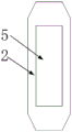
fig. 4 is a schematic structural view of the outer ring type horizontal stiffener plate according to the present invention.
The concrete-filled steel tube reinforced concrete column comprises a rectangular concrete-filled steel tube column 1, an outer ring type horizontal stiffening plate 2, a web plate 3, an H-shaped steel beam 4 and a perforation 5.
Detailed Description
The invention is described in detail below with reference to the figures and specific embodiments. Note that the following description of the embodiments is merely a substantial example, and the present invention is not intended to be limited to the application or the use thereof, and is not limited to the following embodiments.
Examples
An outer ring type beam column rigid connection node is used for beam column joints of building partitions, as shown in figures 1-4, the connection node comprises a rectangular steel tube concrete column 1, a plurality of H-shaped steel beams 4, two outer ring type horizontal stiffening plates 2 and four web plates 3, a perforation 5 matched with the cross section of the rectangular steel tube concrete column 1 in shape is arranged in the middle of each outer ring type horizontal stiffening plate 2, each outer ring type horizontal stiffening plate 2 is sleeved on the periphery of the rectangular steel tube concrete column 1, the web plates 3 are respectively arranged on four side faces of the rectangular steel tube concrete column 1, the side edges of the web plates 3 are fixedly connected with the rectangular steel tube concrete column 1, the top face of each web plate 3 is fixedly connected with the bottom face of the outer ring type horizontal stiffening plate 2 positioned on the upper portion, the bottom face of each web plate 3 is fixedly connected with the top face of the outer ring type horizontal stiffening plate 2 positioned on the upper portion, the H-shaped steel beams 4 are fixedly connected with the outer ring type horizontal stiffening plates 2 and the side faces of the web plates 3, the width of the rectangular concrete-filled steel tube column 1 is matched with the thickness of a building partition wall, and particularly, the width of the rectangular concrete-filled steel tube column 1 is equal to that of the building partition wall or is less than 10cm wider than that of the building partition wall, so that the connecting node can be hidden in the building partition wall, and the indoor effect of not exposing the column is achieved.
For the structure of the outer ring type horizontal stiffening plate 2, in order to be connected with the rectangular concrete filled steel tube column 1 conveniently, the application range and the structural strength of the structure are improved, the cross section of the outer ring type horizontal stiffening plate 2 is octagonal, four side edges of the outer ring type horizontal stiffening plate 2 are parallel to the side surfaces of the rectangular concrete filled steel tube column 1 respectively, the fact that the follow-up H-shaped steel beam 4 is perpendicular to the side surfaces of the rectangular concrete filled steel tube column 1 when being connected is ensured, and the side edges of the cross section octagon of the outer ring type horizontal stiffening plate 2 are long edges, transition edges, short edges, transition edges, long edges, transition edges, short edges and transition edges in sequence as shown in fig. 4.
In addition, the thickness of the outer ring type horizontal stiffening plate 2 is larger than the thickness of the flange of the H-shaped steel beam 4, and the thickness of the outer ring type horizontal stiffening plate 2 is at least 2mm thicker than that of the flange of the H-shaped steel beam 4.
All parts of the invention are fixedly connected in a welding mode, wherein the web plate 3 and the outer ring type horizontal stiffening plate 2 are pre-welded with the rectangular steel pipe concrete column 1 before leaving factory, so that the integrated prefabrication of the connection node is realized, and when the construction is carried out in a building partition scene, the H-shaped steel beams 4 are welded and connected according to requirements. The invention realizes the connection of beam-column nodes without additional assembly components.
Specifically, the side of the web plate 3 is fixedly connected with the rectangular steel pipe concrete column 1 and the outer ring type horizontal stiffening plate 2 through full penetration welding, and the outer ring type horizontal stiffening plate 2 is fixedly connected with the rectangular steel pipe concrete column 1 through full penetration welding.
In this embodiment, for the connection form of the H-shaped steel beam 4 in one connection node, the two outer ring type horizontal stiffening plates 2 are respectively a first stiffening plate and a second stiffening plate, the first stiffening plate is located above the second stiffening plate, the side surface of the first stiffening plate is fixedly connected with the end of the upper flange of the H-shaped steel beam 4, the side surface of the second stiffening plate is fixedly connected with the end of the lower flange of the H-shaped steel beam 4, the side surface of the web 3 is fixedly connected with the end of the web of the H-shaped steel beam 4, and the H-shaped steel beam 4 is fixedly connected with the first stiffening plate, the second stiffening plate and the web 3 by means of bolting and welding.
The H-shaped steel beams 4 of the present invention may be provided in four as shown in fig. 1, or two as shown in fig. 3, and arranged according to the construction requirements of the site.
The above embodiments are merely examples and do not limit the scope of the present invention. These embodiments may be implemented in other various manners, and various omissions, substitutions, and changes may be made without departing from the technical spirit of the present invention.

Claims (10)

1. The outer ring type beam column rigid connection node is characterized by being used at a beam column connection part of a building partition wall, and comprises a rectangular steel pipe concrete column (1), a plurality of H-shaped steel beams (4), two outer ring type horizontal stiffening plates (2) and four web plates (3), wherein the middle part of each outer ring type horizontal stiffening plate (2) is provided with a through hole (5) matched with the cross section of the rectangular steel pipe concrete column (1) in shape, the outer ring type horizontal stiffening plates (2) are sleeved on the peripheral sides of the rectangular steel pipe concrete column (1), the web plates (3) are respectively arranged on four side surfaces of the rectangular steel pipe concrete column (1), the side edges of the web plates (3) are fixedly connected with the rectangular steel pipe concrete column (1), and the top surfaces and the bottom surfaces of the web plates (3) are respectively and fixedly connected with the two outer ring type horizontal stiffening plates (2), the H-shaped steel beam (4) is fixedly connected with the side faces of the outer ring type horizontal stiffening plate (2) and the web plate (3), and the width of the rectangular concrete-filled steel tube column (1) is matched with the thickness of a building partition wall.
2. The rigid connection node of an outer ring type beam column as claimed in claim 1, wherein the side edges of the web plate (3) are fixedly connected with the rectangular concrete-filled steel tube column (1) and the outer ring type horizontal stiffening plate (2) through full penetration welding.
3. The rigid connection node of an outer ring type beam column as claimed in claim 1, wherein the outer ring type horizontal stiffening plate (2) is fixedly connected with the rectangular concrete filled steel tube column (1) by full penetration welding.
4. The rigid outer ring beam-column connection node as claimed in claim 1, wherein said two outer ring horizontal stiffener plates (2) are a first stiffener plate and a second stiffener plate, respectively, said first stiffener plate being located above said second stiffener plate,
the side face of the first stiffening plate is fixedly connected with the tail end of the upper flange of the H-shaped steel beam (4), the side face of the second stiffening plate is fixedly connected with the tail end of the lower flange of the H-shaped steel beam (4), and the side face of the web plate (3) is fixedly connected with the tail end of the web plate of the H-shaped steel beam (4).
5. The rigid connection node of an outer ring type beam column as claimed in claim 4, wherein the H-shaped steel beam (4) is fixedly connected with the first stiffening plate, the second stiffening plate and the web plate (3) by means of bolt welding.
6. The rigid connection node of an outer ring type beam-column according to claim 1, wherein the cross-sectional shape of the outer ring type horizontal stiffening plate (2) is octagonal, and four side edges of the outer ring type horizontal stiffening plate (2) are respectively parallel to the side surfaces of the rectangular concrete-filled steel tube column (1).
7. An outer ring type beam-column rigid connection node as claimed in claim 1, wherein the thickness of the outer ring type horizontal stiffening plate (2) is greater than the thickness of the flange of the H-shaped steel beam (4).
8. An outer ring type beam-column rigid connection node as claimed in claim 7, wherein said outer ring type horizontal stiffening plate (2) is at least 2mm thicker than the flanges of the H-shaped steel beam (4).
9. A rigid connection node of a beam-column type with outer rings according to claim 1, characterized in that said connection node comprises two H-beams (4).
10. A rigid connection node of an outer ring beam column according to claim 1, characterized in that said connection node comprises four H-beams (4).
CN202110868099.7A 2021-07-30 2021-07-30 Outer ring type beam column rigid connection node Pending CN113605541A (en)

Priority Applications (1)

Application Number Priority Date Filing Date Title
CN202110868099.7A CN113605541A (en) 2021-07-30 2021-07-30 Outer ring type beam column rigid connection node

Applications Claiming Priority (1)

Application Number Priority Date Filing Date Title
CN202110868099.7A CN113605541A (en) 2021-07-30 2021-07-30 Outer ring type beam column rigid connection node

Publications (1)

Publication Number Publication Date
CN113605541A true CN113605541A (en) 2021-11-05

Family

ID=78306136

Family Applications (1)

Application Number Title Priority Date Filing Date
CN202110868099.7A Pending CN113605541A (en) 2021-07-30 2021-07-30 Outer ring type beam column rigid connection node

Country Status (1)

Country Link
CN (1) CN113605541A (en)

Cited By (2)

* Cited by examiner, † Cited by third party
Publication number Priority date Publication date Assignee Title
CN116290373A (en) * 2022-12-06 2023-06-23 同圆设计集团股份有限公司 Steel frame assembled house system of trapezoid concrete filled steel tubular column and construction method
CN118997318A (en) * 2024-10-24 2024-11-22 中铁四局集团有限公司 Oblique connection node of concrete filled steel tube column and section steel beam and construction method thereof

Citations (5)

* Cited by examiner, † Cited by third party
Publication number Priority date Publication date Assignee Title
CN105714939A (en) * 2016-04-13 2016-06-29 长安大学 Steel pipe concrete column-steel beam outer separation plate type node structure and construction method thereof
CN107386463A (en) * 2017-08-30 2017-11-24 天津大学 A kind of lower logical upper link point
CN207295999U (en) * 2017-10-16 2018-05-01 浙江中南建设集团钢结构有限公司 Girder steel and steel core concrete column Hybrid connections node
WO2019200726A1 (en) * 2018-04-20 2019-10-24 青岛理工大学 Assembled intelligent node with particle damping bin energy consumption, and method for installing same
CN216973760U (en) * 2021-07-30 2022-07-15 同济大学建筑设计研究院(集团)有限公司 Outer ring type beam column rigid connection node

Patent Citations (5)

* Cited by examiner, † Cited by third party
Publication number Priority date Publication date Assignee Title
CN105714939A (en) * 2016-04-13 2016-06-29 长安大学 Steel pipe concrete column-steel beam outer separation plate type node structure and construction method thereof
CN107386463A (en) * 2017-08-30 2017-11-24 天津大学 A kind of lower logical upper link point
CN207295999U (en) * 2017-10-16 2018-05-01 浙江中南建设集团钢结构有限公司 Girder steel and steel core concrete column Hybrid connections node
WO2019200726A1 (en) * 2018-04-20 2019-10-24 青岛理工大学 Assembled intelligent node with particle damping bin energy consumption, and method for installing same
CN216973760U (en) * 2021-07-30 2022-07-15 同济大学建筑设计研究院(集团)有限公司 Outer ring type beam column rigid connection node

Cited By (3)

* Cited by examiner, † Cited by third party
Publication number Priority date Publication date Assignee Title
CN116290373A (en) * 2022-12-06 2023-06-23 同圆设计集团股份有限公司 Steel frame assembled house system of trapezoid concrete filled steel tubular column and construction method
CN116290373B (en) * 2022-12-06 2024-04-26 同圆设计集团股份有限公司 Steel frame assembled house system of trapezoid concrete filled steel tubular column and construction method
CN118997318A (en) * 2024-10-24 2024-11-22 中铁四局集团有限公司 Oblique connection node of concrete filled steel tube column and section steel beam and construction method thereof

Similar Documents

Publication Publication Date Title
CN110291261B (en) Nodal core for connecting columns and beams and method of connecting columns and beams using the same
KR102079008B1 (en) E-z connecting structure for beam and column wherein the end-moment and bending resistibility are reinforced
KR101174548B1 (en) Column system of concrete filled steel tube
CN105064503A (en) Steel tube and core tube mixed structure
CN205502304U (en) Consolidate double steel plates compound shear wall
CN108193771A (en) A kind of assembling rectangular steel-tube concrete column-girder steel partition board perforation node
CN102635166A (en) Connecting node of square steel pipe column and H-shaped steel beams
CN105064512A (en) Connecting structure of circular steel tube concrete column and steel beam
CN111119336A (en) Y-shaped vertical face intersection conversion node formed by welding box-type steel pipes and application
WO2023202490A1 (en) Built-in laced-type lattice column double steel plate shear wall having wall-beam joint region
CN208056293U (en) A kind of assembling rectangular steel-tube concrete column-girder steel partition board perforation node
CN111042323A (en) X-shaped vertical face intersection node formed by welding box-type steel pipes and application
CN113565207B (en) Assembly type beam-column joint structure and construction method
CN110700422B (en) A DK-shaped space junction node composed of welded box-shaped steel pipes and its application
CN216108977U (en) Assembled square steel pipe column-H shaped steel roof beam-baffle link up node
CN116290340A (en) A prefabricated square concrete filled steel tube joint for comprehensive lifting and anti-collapse
CN216973760U (en) Outer ring type beam column rigid connection node
CN216713336U (en) Double-limb spliced beam and steel pipe column and double-limb spliced beam assembly type beam column joint
CN112049257B (en) H-shaped steel beam-column connection flange node and preparation method
CN206245479U (en) A kind of equivalent wall unit of composite steel tunnel support
CN210713250U (en) Prefabricated CFST composite column node area connection structure
CN205502306U (en) Plug welding formula double steel plates compound shear wall
CN108487549A (en) Prefabricated function recoverable steel frame concrete composite column and its installation method
CN112049259A (en) Angle steel node of embedded connecting piece for H-shaped steel beam-column connection and preparation method
CN103243816B (en) Can open the door hole steel truss support and containing this support steel truss tubular construction

Legal Events

Date Code Title Description
PB01 Publication
PB01 Publication
SE01 Entry into force of request for substantive examination
RJ01 Rejection of invention patent application after publication

Application publication date: 20211105