CN114618264A - CO extraction and concentration from flue gas by secondary adsorption technology2And applications thereof - Google Patents
CO extraction and concentration from flue gas by secondary adsorption technology2And applications thereof Download PDFInfo
- Publication number
- CN114618264A CN114618264A CN202210280856.3A CN202210280856A CN114618264A CN 114618264 A CN114618264 A CN 114618264A CN 202210280856 A CN202210280856 A CN 202210280856A CN 114618264 A CN114618264 A CN 114618264A
- Authority
- CN
- China
- Prior art keywords
- gas
- adsorption
- secondary adsorption
- flue gas
- pressure
- Prior art date
- Legal status (The legal status is an assumption and is not a legal conclusion. Google has not performed a legal analysis and makes no representation as to the accuracy of the status listed.)
- Pending
Links
- 238000001179 sorption measurement Methods 0.000 title claims abstract description 160
- 239000003546 flue gas Substances 0.000 title claims abstract description 34
- UGFAIRIUMAVXCW-UHFFFAOYSA-N Carbon monoxide Chemical compound [O+]#[C-] UGFAIRIUMAVXCW-UHFFFAOYSA-N 0.000 title claims abstract description 33
- 238000000658 coextraction Methods 0.000 title claims description 5
- CURLTUGMZLYLDI-UHFFFAOYSA-N Carbon dioxide Chemical compound O=C=O CURLTUGMZLYLDI-UHFFFAOYSA-N 0.000 claims abstract description 69
- 229910002092 carbon dioxide Inorganic materials 0.000 claims abstract description 56
- 238000000034 method Methods 0.000 claims abstract description 54
- 239000001569 carbon dioxide Substances 0.000 claims abstract description 33
- 238000005516 engineering process Methods 0.000 claims abstract description 13
- 239000007789 gas Substances 0.000 claims description 139
- 239000003463 adsorbent Substances 0.000 claims description 40
- 230000007246 mechanism Effects 0.000 claims description 25
- 238000009826 distribution Methods 0.000 claims description 22
- 230000008569 process Effects 0.000 claims description 13
- 230000002441 reversible effect Effects 0.000 claims description 7
- 238000000605 extraction Methods 0.000 claims description 3
- 238000010521 absorption reaction Methods 0.000 claims 1
- 238000004134 energy conservation Methods 0.000 abstract description 6
- 230000009467 reduction Effects 0.000 abstract description 6
- 238000005265 energy consumption Methods 0.000 abstract description 5
- 230000002860 competitive effect Effects 0.000 abstract description 3
- 238000004519 manufacturing process Methods 0.000 abstract description 3
- 238000000926 separation method Methods 0.000 description 15
- OKTJSMMVPCPJKN-UHFFFAOYSA-N Carbon Chemical compound [C] OKTJSMMVPCPJKN-UHFFFAOYSA-N 0.000 description 14
- IJGRMHOSHXDMSA-UHFFFAOYSA-N Atomic nitrogen Chemical compound N#N IJGRMHOSHXDMSA-UHFFFAOYSA-N 0.000 description 11
- 238000009434 installation Methods 0.000 description 9
- 229910052799 carbon Inorganic materials 0.000 description 6
- 238000003825 pressing Methods 0.000 description 6
- VYPSYNLAJGMNEJ-UHFFFAOYSA-N Silicium dioxide Chemical compound O=[Si]=O VYPSYNLAJGMNEJ-UHFFFAOYSA-N 0.000 description 5
- 239000002156 adsorbate Substances 0.000 description 5
- 239000002808 molecular sieve Substances 0.000 description 5
- 229910052757 nitrogen Inorganic materials 0.000 description 5
- 239000011148 porous material Substances 0.000 description 5
- URGAHOPLAPQHLN-UHFFFAOYSA-N sodium aluminosilicate Chemical compound [Na+].[Al+3].[O-][Si]([O-])=O.[O-][Si]([O-])=O URGAHOPLAPQHLN-UHFFFAOYSA-N 0.000 description 5
- 230000003139 buffering effect Effects 0.000 description 4
- XLYOFNOQVPJJNP-UHFFFAOYSA-N water Substances O XLYOFNOQVPJJNP-UHFFFAOYSA-N 0.000 description 4
- QVGXLLKOCUKJST-UHFFFAOYSA-N atomic oxygen Chemical compound [O] QVGXLLKOCUKJST-UHFFFAOYSA-N 0.000 description 3
- 238000013016 damping Methods 0.000 description 3
- 238000003795 desorption Methods 0.000 description 3
- 239000006185 dispersion Substances 0.000 description 3
- 239000001301 oxygen Substances 0.000 description 3
- 229910052760 oxygen Inorganic materials 0.000 description 3
- 229910002027 silica gel Inorganic materials 0.000 description 3
- 239000000741 silica gel Substances 0.000 description 3
- 239000007787 solid Substances 0.000 description 3
- 239000000126 substance Substances 0.000 description 3
- PNEYBMLMFCGWSK-UHFFFAOYSA-N aluminium oxide Inorganic materials [O-2].[O-2].[O-2].[Al+3].[Al+3] PNEYBMLMFCGWSK-UHFFFAOYSA-N 0.000 description 2
- 238000002485 combustion reaction Methods 0.000 description 2
- 238000001914 filtration Methods 0.000 description 2
- 238000000746 purification Methods 0.000 description 2
- 238000007493 shaping process Methods 0.000 description 2
- 239000004115 Sodium Silicate Substances 0.000 description 1
- 229910021536 Zeolite Inorganic materials 0.000 description 1
- 230000000274 adsorptive effect Effects 0.000 description 1
- RREGISFBPQOLTM-UHFFFAOYSA-N alumane;trihydrate Chemical compound O.O.O.[AlH3] RREGISFBPQOLTM-UHFFFAOYSA-N 0.000 description 1
- 229910000323 aluminium silicate Inorganic materials 0.000 description 1
- 230000001174 ascending effect Effects 0.000 description 1
- 230000009286 beneficial effect Effects 0.000 description 1
- 230000008901 benefit Effects 0.000 description 1
- 238000006243 chemical reaction Methods 0.000 description 1
- 239000003795 chemical substances by application Substances 0.000 description 1
- 239000008119 colloidal silica Substances 0.000 description 1
- 239000002131 composite material Substances 0.000 description 1
- 238000009833 condensation Methods 0.000 description 1
- 230000005494 condensation Effects 0.000 description 1
- 238000010276 construction Methods 0.000 description 1
- 230000007423 decrease Effects 0.000 description 1
- 230000018044 dehydration Effects 0.000 description 1
- 238000006297 dehydration reaction Methods 0.000 description 1
- 238000005137 deposition process Methods 0.000 description 1
- 238000013461 design Methods 0.000 description 1
- 229910001873 dinitrogen Inorganic materials 0.000 description 1
- HNPSIPDUKPIQMN-UHFFFAOYSA-N dioxosilane;oxo(oxoalumanyloxy)alumane Chemical compound O=[Si]=O.O=[Al]O[Al]=O HNPSIPDUKPIQMN-UHFFFAOYSA-N 0.000 description 1
- 238000001035 drying Methods 0.000 description 1
- 230000000694 effects Effects 0.000 description 1
- 230000002349 favourable effect Effects 0.000 description 1
- 229910001679 gibbsite Inorganic materials 0.000 description 1
- 229930195733 hydrocarbon Natural products 0.000 description 1
- 150000002430 hydrocarbons Chemical class 0.000 description 1
- 239000012535 impurity Substances 0.000 description 1
- 239000007788 liquid Substances 0.000 description 1
- 238000012423 maintenance Methods 0.000 description 1
- 239000000463 material Substances 0.000 description 1
- 229910052751 metal Inorganic materials 0.000 description 1
- 239000002184 metal Substances 0.000 description 1
- 150000007522 mineralic acids Chemical class 0.000 description 1
- 238000002156 mixing Methods 0.000 description 1
- 239000000203 mixture Substances 0.000 description 1
- 230000004048 modification Effects 0.000 description 1
- 238000012986 modification Methods 0.000 description 1
- 230000036961 partial effect Effects 0.000 description 1
- 239000002245 particle Substances 0.000 description 1
- 230000035515 penetration Effects 0.000 description 1
- 230000000737 periodic effect Effects 0.000 description 1
- 238000004375 physisorption Methods 0.000 description 1
- 238000012545 processing Methods 0.000 description 1
- 230000002035 prolonged effect Effects 0.000 description 1
- 238000005086 pumping Methods 0.000 description 1
- 239000002994 raw material Substances 0.000 description 1
- 238000004064 recycling Methods 0.000 description 1
- 230000008929 regeneration Effects 0.000 description 1
- 238000011069 regeneration method Methods 0.000 description 1
- 238000009991 scouring Methods 0.000 description 1
- NTHWMYGWWRZVTN-UHFFFAOYSA-N sodium silicate Chemical compound [Na+].[Na+].[O-][Si]([O-])=O NTHWMYGWWRZVTN-UHFFFAOYSA-N 0.000 description 1
- 229910052911 sodium silicate Inorganic materials 0.000 description 1
- 239000012798 spherical particle Substances 0.000 description 1
- 229910002029 synthetic silica gel Inorganic materials 0.000 description 1
- 238000007725 thermal activation Methods 0.000 description 1
- 238000003466 welding Methods 0.000 description 1
- 239000010457 zeolite Substances 0.000 description 1
Images


Classifications
-
- B—PERFORMING OPERATIONS; TRANSPORTING
- B01—PHYSICAL OR CHEMICAL PROCESSES OR APPARATUS IN GENERAL
- B01D—SEPARATION
- B01D53/00—Separation of gases or vapours; Recovering vapours of volatile solvents from gases; Chemical or biological purification of waste gases, e.g. engine exhaust gases, smoke, fumes, flue gases, aerosols
- B01D53/02—Separation of gases or vapours; Recovering vapours of volatile solvents from gases; Chemical or biological purification of waste gases, e.g. engine exhaust gases, smoke, fumes, flue gases, aerosols by adsorption, e.g. preparative gas chromatography
- B01D53/04—Separation of gases or vapours; Recovering vapours of volatile solvents from gases; Chemical or biological purification of waste gases, e.g. engine exhaust gases, smoke, fumes, flue gases, aerosols by adsorption, e.g. preparative gas chromatography with stationary adsorbents
- B01D53/047—Pressure swing adsorption
-
- C—CHEMISTRY; METALLURGY
- C01—INORGANIC CHEMISTRY
- C01B—NON-METALLIC ELEMENTS; COMPOUNDS THEREOF; METALLOIDS OR COMPOUNDS THEREOF NOT COVERED BY SUBCLASS C01C
- C01B32/00—Carbon; Compounds thereof
- C01B32/50—Carbon dioxide
-
- B—PERFORMING OPERATIONS; TRANSPORTING
- B01—PHYSICAL OR CHEMICAL PROCESSES OR APPARATUS IN GENERAL
- B01D—SEPARATION
- B01D2257/00—Components to be removed
- B01D2257/50—Carbon oxides
- B01D2257/504—Carbon dioxide
Landscapes
- Chemical & Material Sciences (AREA)
- Chemical Kinetics & Catalysis (AREA)
- Organic Chemistry (AREA)
- Engineering & Computer Science (AREA)
- Analytical Chemistry (AREA)
- General Chemical & Material Sciences (AREA)
- Oil, Petroleum & Natural Gas (AREA)
- Inorganic Chemistry (AREA)
- Separation Of Gases By Adsorption (AREA)
- Treating Waste Gases (AREA)
Abstract
The invention discloses a method for extracting and concentrating CO from flue gas by using secondary adsorption technology2The method and the application thereof comprise the following steps: pressure boosting, primary adsorption, pressure equalizing, secondary adsorption and CO2Collecting, namely conveying the existing product carbon dioxide to a first-stage pressure swing adsorption device through secondary adsorption, and obtaining CO with the concentration of 80-99.9% in the first-stage pressure swing adsorption at one time2Compared with the existing mode of adopting two-section pressure swing adsorption devices, the method greatly reduces the power consumption and reduces the CO2The production cost of the method is reduced, the purposes of energy conservation and consumption reduction are realized, and the competitive power of the product is improved.
Description
Technical Field
The invention relates to the field of flue gas treatment, in particular to a method for extracting and concentrating CO from flue gas by using a secondary adsorption technology2And applications thereof.
Background
In order to reduce carbon emission, save energy and reduce consumption. The tail gas of the factory flue needs to be treated for producing high-concentration carbon dioxideGas and high-purity nitrogen gas are prepared. But because of CO in the flue gas2The content of the carbon dioxide is low, and the prior art adopts a two-section pressure swing adsorption technology to separate and purify the carbon dioxide.
For convenience of description, the operating pressure is 0.3MPa, and the amount of the treated gas is 10000Nm3/h (CO)2Content 14%, N2The content is 73%; the oxygen content is 6%; 7% water separation) as follows:
the low pressure flue gas is pressurized to 0.3MPa (compressor shaft power 672 kw) by a compressor, and CO is adsorbed in the first stage by pressure swing adsorption2The concentration is increased to 70%. The concentrated carbon dioxide is desorbed by a vacuum pump (the power of a vacuum pump shaft is 168 kw). Then the pressure of the compressor is increased to 0.3MPa (the shaft power of the compressor is 154 kw), and CO is absorbed by two-stage pressure swing adsorption2The concentration is increased to 95 percent and then desorbed by a vacuum pump (the power of a vacuum pump shaft is 105 kw) to obtain CO with the concentration of 95 percent2And (5) producing gas. In this process, CO2The gas needs to go through two compressors and two vacuums, the running power consumption is too high (the total power consumption is 672+168+154+105=1099kw), the objection of energy conservation and consumption reduction is reduced, and therefore, the purification of high-concentration CO from the flue gas with higher energy conservation and consumption reduction needs to be provided2A method.
Disclosure of Invention
The invention aims to solve the problems in the prior art and provide a method for extracting and concentrating CO from flue gas by using a secondary adsorption technology2And applications thereof.
The technical purpose of the invention is realized by the following technical scheme:
CO extraction and concentration from flue gas by secondary adsorption technology2The method comprises the following steps:
s1, boosting, namely boosting the low-pressure flue gas by using a dynamic device, wherein the dynamic device can be a compressor, and the flue gas is combustion tail gas;
s2, primary adsorption, separating the flue gas after pressure rise through a first-stage pressure swing adsorption device (2) to obtain concentrated CO2;
S3, equalizing pressure, and adsorbing the adsorbed CO2Carrying out a pressure equalizing process;
s4, secondary adsorption, extracting part of concentrated CO2Performing secondary adsorption again by the pressure swing adsorption device;
s5, collecting to obtain qualified CO2One part of the gas is used for secondary adsorption, and the rest is sent out as product gas.
The first-stage pressure swing adsorption device consists of a plurality of carbon dioxide adsorption towers and related control instruments.
CO obtained after one-time adsorption and pressure equalizing process2The gas concentration is 50-80%, and is used for improving CO2Concentration, extracting a part of concentrated CO from gas (stripping gas) discharged from reverse discharge or vacuum pump2,The extraction ratio is 10-90% of the total amount of gas (desorbed gas), and the secondary adsorption is carried out by the first-stage pressure swing adsorption device again.
The secondary adsorption process is completed by single implementation or multiple superposition, and finally CO in the whole adsorption tower is obtained2The concentration reaches more than 80-99.9%.
The collection is composed of 1 or more vacuum pumps, and after secondary adsorption, CO in the adsorption tower is adsorbed2The gas concentration reaches 80-99.9%, the part of gas is reduced to low pressure of 0-20 KPag through reverse discharge, then evacuation is carried out by using a vacuum pump, part of the reversely discharged low-pressure gas and evacuated gas is used as raw gas for secondary adsorption, and the rest part of the reversely discharged low-pressure gas and evacuated gas is output as product gas.
Pressure Swing Adsorption (PSA) technology is a new gas separation and purification technology developed over 30 years, and adsorption means: a phenomenon and process in which molecules of a less dense species are enriched at the surface of a more dense species when the two species are brought into contact in different phases. Substances having an adsorptive action (typically porous solids of relatively high density) are referred to as adsorbents, and substances to be adsorbed (typically gases or liquids of relatively low density) are referred to as adsorbents. Adsorption can be divided into four broad categories, depending on its nature, namely: chemisorption, active adsorption, capillary condensation and physisorption. Adsorption in Pressure Swing Adsorption (PSA) gas separation devices is primarily physical adsorption.
Physical adsorption refers to adsorption that relies on molecular forces (including van der waals and electromagnetic forces) between the adsorbent and adsorbate molecules. The method is characterized in that: there is no chemical reaction in the adsorption process, the adsorption process is very fast, the dynamic balance among the substances participating in the adsorption can be completed in a moment, and the adsorption is completely reversible.
Pressure swing adsorption gas separation processes are achieved because of two basic properties of adsorbents in this physical adsorption: the first is different adsorption capacity to different components, and the second is that the adsorption capacity of adsorbate on the adsorbent increases with the partial pressure of adsorbate and decreases with the increase of adsorption temperature. By utilizing the first property of the adsorbent, the preferential adsorption of certain components in the mixed gas can be realized, and other components can be purified; by utilizing the second property of the adsorbent, the adsorbent can be adsorbed at low temperature and high pressure and desorbed and regenerated at high temperature and low pressure, so that the adsorption and regeneration cycle of the adsorbent is formed, and the aim of continuously separating gas is fulfilled.
Industrial PSA-CO2The adsorbent selected by the device is solid particles with large specific surface area, and mainly comprises the following components: activated alumina, activated carbon, silica gel and molecular sieve adsorbents; in addition, special adsorbing materials developed for selective adsorption of certain components, such as CO special adsorbent, carbon molecular sieve and the like, are provided. The most important physical characteristics of the adsorbent include pore volume, pore size distribution, surface area and surface properties, etc. Different adsorbents have different adsorption capacities and adsorption capacities for the components in the mixed gas due to different pore size distributions, different specific surface areas, and different surface properties.
The adsorption performance of the adsorbent on various gases is mainly evaluated by an adsorption isotherm and a penetration curve under dynamic conditions which are determined experimentally. Excellent adsorption performance and large adsorption capacity are basic conditions for realizing adsorption separation.
At the same time, to achieve industrially effective separation, it must also be considered that the separation coefficient of the adsorbent for each component should be as large as possible. The separation factor means: when the adsorption equilibrium is reached, the ratio of (residual amount of weakly adsorbed component in dead space of the adsorption bed/total amount of weakly adsorbed component in the adsorption bed) to (residual amount of strongly adsorbed component in dead space of the adsorption bed/total amount of strongly adsorbed component in the adsorption bed). The greater the separation coefficient, the easier the separation. Generally, the separation factor of the adsorbent in the pressure swing adsorption gas separation unit is not preferably less than 3.
In addition, the contradiction between adsorption and desorption should be considered in the industrial pressure swing adsorption process. In general, the easier the adsorption, the more difficult the desorption. For example, for strong adsorbates such as C5 and C6, an adsorbent with relatively weak adsorption capacity such as silica gel should be selected so that the adsorption capacity is appropriate and desorption is easy; and for N2、O2And for weak adsorbates such as CO, adsorbents with relatively strong adsorption capacity such as molecular sieves and the like are selected, so that the adsorption capacity is larger and the separation coefficient is higher.
In addition, the adsorbent should have sufficient strength and attrition resistance during adsorption because the adsorbent is subjected to frequent scouring by the gas stream due to the periodic variation of pressure in the adsorbent bed.
Among the adsorbents commonly used in pressure swing adsorption gas separation devices, activated alumina is a solid having a strong affinity for water, and is generally prepared by thermal dehydration or thermal activation of aluminum trihydrate or gibbsite, and is mainly used for drying gas.
The silica gel adsorbent is a synthetic amorphous silica which is a rigid continuous network of spherical particles of colloidal silica, generally prepared by mixing a sodium silicate solution with an inorganic acid, and has a strong affinity for water, hydrocarbons and CO2The components also have stronger adsorption capacity.
The activated carbon adsorbent is characterized in that: the surface of the adsorbent is weakly polar or nonpolar, and the surface of the adsorbent is weakly polar or nonpolar, so that the activated carbon becomes a broad-spectrum water-resistant adsorbent capable of adsorbing a large number of weakly polar and nonpolar organic molecules due to the extremely large internal surface area of the activated carbon.
The zeolite molecular sieve adsorbent (5A, 13X) is a crystalline meta-aluminosilicate containing alkaline earth elements,belongs to strong polar adsorbent, has very consistent pore size structure and extremely strong adsorption selectivity, and can be used for treating CO, CH4 and N2、Ar、O2And the like have higher adsorption capacity.
The carbon molecular sieve is a special adsorbent which is prepared by processing carbon serving as a raw material through a special carbon deposition process and is specially used for purifying nitrogen in air, so that the pore size distribution of the adsorbent is very concentrated and is only slightly larger than the diameter of oxygen molecules, and the separation of nitrogen and oxygen in air is very facilitated.
For gas sources with complex composition, in practical application, a plurality of adsorbents are often needed and are sequentially filled in layers according to adsorption performance to form a composite adsorption bed, so that the purpose of separating required product components can be achieved.
Preferably, the first-stage pressure swing adsorption device is composed of a plurality of carbon dioxide adsorption towers, each carbon dioxide adsorption tower comprises a tower body, an exhaust port is formed in the top of the tower body, an air inlet is formed in the bottom of the tower body, a carbon dioxide adsorbent is arranged inside the tower body, a gas distributor is arranged at the bottom of the tower body, flue gas enters the carbon dioxide adsorption towers through the air inlets and is adsorbed through the carbon dioxide adsorbent, so that carbon dioxide gas is adsorbed, and the purpose of extracting carbon dioxide from a flue is achieved.
Preferably, the gas distributor comprises a conical plate, a first filter screen, a second filter screen and a flower plate, wherein a through hole is formed in the middle of the conical plate, a plurality of groups of first gas flow hole groups are uniformly distributed on the circumference of the top of the conical plate, a second gas flow hole group is arranged on the flower plate, the first filter screen covers the upper surface of the conical plate, the flower plate is arranged above the through hole and below the second filter screen, the first filter screen and the second filter screen can be metal wire meshes, and can disperse gas through the gas flow hole groups, so that the gas entering the adsorption tower uniformly enters the carbon dioxide adsorbent, the adsorption efficiency of carbon dioxide in the tower is improved, and impurities mixed in the gas can be removed through the first filter screen and the second filter screen, so that the later adsorption is facilitated, is favorable for improving the purity of the product.
Meanwhile, the conical plate and the flower plate are of separate structures, so that the strength of the gas distributor can be improved.
Preferably, the bottom of circular cone shaped plate still is equipped with supporting mechanism, supporting mechanism is including the support ring that is located the middle part, the support ring circumference distributes there is the backup pad, two the shaping has the gas circulation space between the backup pad, can play the effect of support to gas distributor through the backup pad, the bottom shape cooperation at the bottom of the below radian and the tower of backup pad for the backup pad can stand the bottom at the bottom of the tower.
Preferably, the supporting mechanism's below is equipped with reposition of redundant personnel buffer gear, reposition of redundant personnel buffer gear is including the baffle, the marginal circumference array of baffle is to the ascending gas flow distribution plate of slope, per two the shaping has the backup pad to place the clearance between the gas flow distribution plate, the last diffluence hole of having seted up of gas flow distribution plate, the trompil direction of diffluence hole inclines to the end of gas flow distribution plate, makes the gas that enters into to the tower through the air inlet of adsorption tower after stepping up from the compressor through reposition of redundant personnel buffer gear, passes through the baffle earlier, later to dispersion all around, to diffusing on the gas flow distribution plate, on the diffluence hole of gas distributor flows in again through the diffluence hole, can reduce the gas flow rate through the dispersion to gas too big, to the impact force that the conical plate produced, reduce the loss of board, increase of service life, the current conical plate that especially can be fine solution leads to the bulk strength reduction of conical plate owing to seting a lot of intensive gas flow hole And (5) problems are solved.
Preferably, the backup pad is close to be equipped with the installation ear on the lateral wall of baffle, set up on the baffle with the corresponding mounting hole in hole of installation ear, the mounting hole with it has fixing bolt to run through on the installation ear, fixing bolt's terminal threaded connection has the nut, passes the hole and the mounting hole of installation ear through fixing bolt, later connects through the nut, realizes shunting buffer gear and supporting mechanism's dismantlement and is connected, during the installation, only needs to be connected shunting buffer gear and supporting mechanism in advance, during the installation supporting mechanism, can accomplish shunting buffer gear's installation, the installation of being convenient for, simultaneously through detachable construction, the maintenance in the later stage of being convenient for.
Preferably, two adjacent first gas flow hole groups are fixedly connected with first fixing columns, the first fixing columns are at least distributed along the radial direction of the conical plate, each first fixing column is perpendicular to the outer side wall of the conical plate, at least three second fixing columns are distributed around the through hole of the conical plate along the circumferential direction of the through hole, the first filter screen is sleeved on the conical plate through the first fixing columns, the second filter screen is sleeved on the flower plate through the second fixing columns, the tail ends of the first fixing columns and the second fixing columns are in threaded connection with fixing nuts, holes are not required to be formed in the conical plate in a mode that the fixing columns are directly welded or formed on the conical plate, and gas firstly passes through the flow distribution holes in the conical plate when passing through a cone, the mode of first filter screen and second filter screen of rethread for gas can both carry out abundant filtration, compares with the mode of the direct trompil installation on the circular cone shaped plate of current, can prevent that gas from directly entering into gas adsorption agent from the mounting hole on the circular cone shaped plate, and does not have the step of filtering.
Meanwhile, the mode of fixing columns is directly welded, so that the later stage is more convenient and faster when the first filter screen, the second filter screen, the pressing strips and the pressing rings are assembled.
Preferably, still be equipped with the layering on the circular cone shape board, still be equipped with the clamping ring on the card, the layering cover is established on the first fixed column and be located the top of first filter screen, the clamping ring cover is established on the second fixed column and be located the top of second filter screen can carry out fine fixed to first filter screen and second filter screen.
Preferably, the first gas flow hole group and the second gas flow hole group are both composed of a plurality of gas flow holes arranged in a regular triangle manner.
CO extraction and concentration from flue gas by secondary adsorption technology2The method of (2) is applied to flue tail gas.
In conclusion, the invention has the beneficial effects that:
1. the method adopts the steps of pressure boosting, primary adsorption, pressure equalizing, secondary adsorption and collection, utilizes the existing product carbon dioxide through secondary adsorption and conveys the carbon dioxide to a first-stage pressure swing adsorption device, and CO with the concentration of 80-99.9% is obtained in one-stage pressure swing adsorption2Compared with the existing mode of adopting two-section pressure swing adsorption devices, the method greatly reduces the power consumption and reduces the CO2The production cost is reduced, the purposes of energy conservation and consumption reduction are realized, and the competitive power of the product is improved;
2. the collected carbon dioxide is subjected to secondary adsorption circulation through the pressure swing adsorption device, so that closed circulation of the product carbon dioxide is realized, resource recycling is realized, the purpose of energy conservation is realized, and the economic benefit is improved;
3. according to the invention, the gas entering the adsorption tower from the air inlet of the adsorption tower after being pressurized by the compressor firstly passes through the baffle plate and then is dispersed to the periphery and diffused on the gas splitter plate, and then flows into the splitter holes of the gas distributor through the splitter holes, so that the gas entering the carbon dioxide adsorbent can be uniformly and sufficiently dispersed, the adsorption efficiency of the carbon dioxide in the tower body is further improved, meanwhile, the excessive gas flow rate can be reduced through the dispersion of the gas, the impact force generated on the conical plate is reduced, the loss of the plate is reduced, the service life is prolonged, and the problem that the overall strength of the conical plate is reduced due to the fact that a plurality of dense gas circulation holes are formed in the existing conical plate can be well solved;
4. according to the invention, through a mode of directly welding or forming the fixing columns on the conical plate, holes do not need to be formed on the conical plate, so that when the gas passes through the conical plate, the gas can be fully filtered through the shunting holes on the conical plate and then the first filter screen and the second filter screen.
Drawings
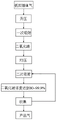
FIG. 1 is a schematic of the process of the present invention;
FIG. 2 is an overall schematic of the present invention;
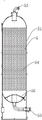
FIG. 3 is a schematic view of a carbon dioxide adsorption column of the present invention;
FIG. 4 is a schematic view of the bottom of a carbon dioxide adsorption column of the present invention;
FIG. 5 is an enlarged schematic view at I of FIG. 4 of the present invention;
FIG. 6 is a schematic view of the gas distributor and support mechanism and shunt buffer mechanism of the present invention after connection;
FIG. 7 is a schematic bottom view of the shunt damping mechanism of the present invention;
FIG. 8 is a schematic top view of the shunt damping mechanism and support mechanism of the present invention assembled;
FIG. 9 is a schematic view of the connection of the baffle and support plate of the shunt buffering mechanism of the present invention;
FIG. 10 is a cross-sectional schematic view of the shunt damping mechanism of the present invention;
FIG. 11 is a schematic view of the arrangement of the first gas flow aperture set of the present invention;
the following specific examples are given by way of illustration only and not by way of limitation, and it will be apparent to those skilled in the art from this disclosure that various changes and modifications can be made in the examples without inventive faculty, and yet still be protected by the scope of the claims.
The present invention will be described in detail below by way of examples with reference to the accompanying drawings.
Example 1:
as shown in FIGS. 1-2, a method for extracting and concentrating CO from flue gas by using secondary adsorption technology2The method comprises the following steps:
s1, boosting, namely boosting the low-pressure flue gas by using a power plant, wherein the flue gas refers to combustion tail gas;
s2, primary adsorption, separating the flue gas after pressure rise through a first-stage pressure swing adsorption device 2 to obtain concentrated CO2;
S3Pressure equalization, adsorbed CO2Carrying out a pressure equalizing process;
s4, secondary adsorption, extracting part of concentrated CO2Performing secondary adsorption again by the pressure swing adsorption device;
s5, collecting to obtain qualified CO2One part of the gas is used for secondary adsorption, and the rest is sent out as product gas.
The first-stage pressure swing adsorption device consists of a plurality of carbon dioxide adsorption towers and related control instruments.
CO obtained after one-time adsorption and pressure equalizing process2The gas concentration is 50-80%, and is used for improving CO2Concentration, extracting a part of concentrated CO from gas (stripping gas) discharged from reverse discharge or vacuum pump2,The extraction ratio is 10-90% of the total amount of gas (desorbed gas), and the secondary adsorption is carried out by the first-stage pressure swing adsorption device again.
The secondary adsorption process is completed by single implementation or multiple superposition, and finally CO in the whole adsorption tower is obtained2The concentration reaches more than 80-99.9%.
The collection is composed of 1 or more vacuum pumps, and CO in the adsorption tower is adsorbed after secondary adsorption2The gas concentration reaches 80-99.9%, the part of gas is reduced to low pressure of 0-20 KPag through reverse discharge, then evacuation is carried out by using a vacuum pump, part of the reversely discharged low-pressure gas and evacuated gas is used as raw gas for secondary adsorption, and the rest part of the reversely discharged low-pressure gas and evacuated gas is output as product gas.
As shown in fig. 1 to 10, the one-stage pressure swing adsorption apparatus 2 is composed of a plurality of carbon dioxide adsorption towers 5, the carbon dioxide adsorption towers 5 include a tower body 51, a gas outlet 52 is disposed at the top of the tower body 51, a gas inlet 53 is disposed at the bottom of the tower body 51, a carbon dioxide adsorbent 54 is disposed inside the tower body 51, a gas distributor 55 is disposed at the bottom of the tower body 51, the gas distributor 55 includes a conical plate 551, a first filter screen 552, a second filter screen 553, and a flower plate 554, a through hole 555 is formed at the middle of the conical plate 551, a plurality of groups of first gas flow hole groups 556 are uniformly distributed on the circumference of the top of the conical plate 551, a second gas flow hole group 557 is disposed on the flower plate 554, the first filter screen 552 covers the upper surface of the conical plate 551, the flower plate 554 is disposed above the through hole 555 and is located below the second filter screen 553, the bottom of the conical plate 551 is further provided with a supporting mechanism 59, the supporting mechanism 59 comprises a supporting ring 591 located in the middle, supporting plates 592 are distributed on the circumference of the supporting ring 591, a gas flow space 593 is formed between the two supporting plates 592, a first fixing column 56 is fixedly connected between each two groups of first gas flow hole groups 556, at least three or more first fixing columns 56 are distributed along the radial direction of the conical plate 551, each first fixing column 56 is perpendicular to the outer side wall of the conical plate 551, at least three or more second fixing columns 57 are distributed along the circumferential direction of the through hole around the through hole 555 of the conical plate 551, the first filter screen 552 is sleeved on the conical plate 551 through the first fixing columns 56, the second filter screen 553 is sleeved on the flower plate 554 through the second fixing columns 57, the end threads of the first fixing column 56 and the second fixing column 57 are connected with a fixing nut 58, a pressing strip 558 is further arranged on the conical plate 551, a pressing ring 559 is further arranged on the pattern plate 554, the pressing strip 558 is sleeved on the first fixing column 56 and located above the first filter screen 552, the pressing ring 559 is sleeved on the second fixing column 57 and located above the second filter screen 553, the first gas circulation hole group 556 and the second gas circulation hole group 557 are respectively composed of a plurality of gas circulation holes which are arranged in a regular triangle manner, the diameter of the gas circulation hole 556 of the first gas circulation hole group 556 is 20, the hole pitch is 30, the diameter of the second gas circulation hole group 557 is 8, the hole pitch is 20, the single side of the contact surface of each hole and the silk screen is inverted by 45 degrees, the depth is 1mm, and burrs can be removed.
As shown in fig. 5 to 9, a flow distribution buffering mechanism 50 is arranged below the supporting mechanism 59, the flow distribution buffering mechanism 50 includes a baffle 501, gas distribution plates 502 inclined upward are arrayed on the edge circumference of the baffle 501, a supporting plate placing gap 503 is formed between every two gas distribution plates 502, a flow distribution hole 504 is formed in each gas distribution plate 502, the opening direction of each flow distribution hole 503 is inclined toward the end of the gas distribution plate 502, the flow distribution buffering mechanism is characterized in that a mounting lug 505 is arranged on the side wall of the supporting plate 592 close to the baffle 501, a mounting hole 506 corresponding to the hole of the mounting lug 505 is formed in the baffle 501, a fixing bolt 507 penetrates through the mounting hole 506 and the mounting lug 505, and a nut 508 is connected to the end of the fixing bolt through a thread.
CO extraction and concentration from flue gas by secondary adsorption technology2The method of (2) is applied to flue tail gas.
The working principle is as follows:
as shown in fig. 1-10, the pretreated low-pressure flue gas is pressurized by a compressor, the pressurized flue gas is separated by a first pressure swing adsorption device 2, enters a carbon dioxide adsorption tower 5, passes through a baffle 506 on a diversion buffer mechanism 50, diffuses a gas diversion plate 502, flows into a diversion hole on a conical plate 551, is filtered by a first filter screen 552 and a second filter screen 553, rises to a region of a carbon dioxide adsorbent 54, adsorbs carbon dioxide, and obtains unadsorbed high-concentration nitrogen and adsorbed CO2Sending the unadsorbed high-concentration nitrogen to a nitrogen making device; pressure equalization of adsorbed CO2The pressure is equalized for 1-N times, the operation pressure is different, the pressure equalizing times are different, and the fan is used for supplying CO2Part of product CO is extracted from the product tank2Then the CO in the whole adsorption tower is subjected to secondary adsorption by a pressure swing adsorption device2The concentration reaches over 95 percent of the design, and qualified CO is obtained by reverse discharge and vacuum pumping2One part of the gas is used for secondary adsorption, the rest part of the gas is sent out as product gas, the existing product carbon dioxide is conveyed to a first-stage pressure swing adsorption device through secondary adsorption, and CO with the concentration of 95% is obtained in one-stage pressure swing adsorption2The gas only needs to be compressed once and vacuumized once in the process, and compared with the existing mode that a two-section pressure swing adsorption device is needed, the power consumption is greatly reduced, and the CO is reduced2The production cost of the method is reduced, the purposes of energy conservation and consumption reduction are realized, and the competitive power of the product is improved.
Claims (10)
1. CO extraction and concentration from flue gas by secondary adsorption technology2The method is characterized by comprising the following steps:
s1, boosting, namely boosting the low-pressure flue gas by using a power plant;
s2, primary adsorption, separating the flue gas after pressure rise through a first-stage pressure swing adsorption device (2) to obtain concentrated CO2;
S3, equalizing pressure, and absorbing the CO obtained in the first absorption2Carrying out a pressure equalizing process;
s4, secondary adsorption, extracting part of concentrated CO2Performing secondary adsorption through the first-stage pressure swing adsorption device (2);
s5, collecting to obtain qualified CO2And returning part of the gas for secondary adsorption, and sending the rest of the gas as product gas.
2. The method of claim 1 for extracting and concentrating CO from flue gas by secondary adsorption2The method is characterized in that the first-stage pressure swing adsorption device (2) consists of a plurality of carbon dioxide adsorption towers (5) and related control instruments.
3. The method of claim 2 for extracting and concentrating CO from flue gas by secondary adsorption2The method is characterized in that CO obtained after one-time adsorption and pressure equalizing process2The gas concentration is 50-80%, and is used for improving CO2Concentration, extracting a part of concentrated CO from gas at the outlet of a reverse-discharge or vacuum pump2The extraction ratio is 10-90% of the total gas amount, and the secondary adsorption is carried out through the first-stage pressure swing adsorption device (2) again.
4. The method of claim 2 for extracting and concentrating CO from flue gas by secondary adsorption2The method is characterized in that the secondary adsorption process is completed by single implementation or multiple superposition, and finally CO in the whole adsorption tower is obtained2The concentration reaches more than 80-99.9%.
5. The method of claim 4 wherein the CO is extracted and concentrated from the flue gas by a secondary adsorption technique2The method is characterized in that the collection is composed of 1 or more vacuum pumps (4), and CO in the adsorption tower is adsorbed after secondary adsorption2The gas concentration reaches 80-99.9%, the part of gas is reduced to low pressure of 0-20 KPag through reverse discharge, then evacuation is carried out by using a vacuum pump, part of the reversely discharged low-pressure gas and evacuated gas is used as raw gas for secondary adsorption, and the rest part of the reversely discharged low-pressure gas and evacuated gas is output as product gas.
6. A method for extracting and concentrating CO from flue gas by secondary adsorption technology according to any one of claims 1-52The method of (2) is applied to flue tail gas.
7. The method of claim 2 for extracting and concentrating CO from flue gas by secondary adsorption2The method is characterized in that the carbon dioxide adsorption tower (5) comprises a tower body (51), an exhaust port (52) is arranged at the top of the tower body (51), an air inlet (53) is arranged at the bottom of the tower body (51), a carbon dioxide adsorbent (54) is arranged inside the tower body (51), and a gas distributor (55) is arranged at the bottom of the tower body (51).
8. The method of claim 7 wherein the CO is extracted and concentrated from the flue gas using a secondary adsorption technique2The method is characterized in that the gas distributor (55) comprises a conical plate (551), a first filter screen (552), a second filter screen (553) and a card (554), wherein through holes (555) are formed in the middle of the conical plate (551), a plurality of groups of first gas through hole groups (556) are uniformly distributed on the circumference of the top of the conical plate (551), the card (554) is provided with the second gas through hole group (557), the first filter screen (552) covers the upper surface of the conical plate (551), and the card (554) is arranged above the through holes (555) and is positioned at the upper surface of the conical plate (551)Below the second filter (553).
9. The method of claim 7 wherein the CO is extracted and concentrated from the flue gas using a secondary adsorption technique2The method is characterized in that the bottom of the conical plate (551) is also provided with a supporting mechanism (59), the supporting mechanism (59) comprises a supporting ring (591) positioned in the middle, supporting plates (592) are distributed on the circumference of the supporting ring (591), and a gas circulation space (593) is formed between the two supporting plates (592).
10. The method of claim 9 for extracting and concentrating CO from flue gas using secondary adsorption technology2The method is characterized in that a shunting buffer mechanism (50) is arranged below the supporting mechanism (59), the shunting buffer mechanism (50) comprises a baffle plate (501), gas distribution plates (502) which are inclined upwards are arrayed on the periphery of the edge of the baffle plate (501), a supporting plate placing gap (503) is formed between every two gas distribution plates (502), a shunting hole (504) is formed in each gas distribution plate (502), and the opening direction of each shunting hole (503) is inclined towards the tail end of each gas distribution plate (502).
Priority Applications (1)
| Application Number | Priority Date | Filing Date | Title |
|---|---|---|---|
| CN202210280856.3A CN114618264A (en) | 2022-03-22 | 2022-03-22 | CO extraction and concentration from flue gas by secondary adsorption technology2And applications thereof |
Applications Claiming Priority (1)
| Application Number | Priority Date | Filing Date | Title |
|---|---|---|---|
| CN202210280856.3A CN114618264A (en) | 2022-03-22 | 2022-03-22 | CO extraction and concentration from flue gas by secondary adsorption technology2And applications thereof |
Publications (1)
| Publication Number | Publication Date |
|---|---|
| CN114618264A true CN114618264A (en) | 2022-06-14 |
Family
ID=81903760
Family Applications (1)
| Application Number | Title | Priority Date | Filing Date |
|---|---|---|---|
| CN202210280856.3A Pending CN114618264A (en) | 2022-03-22 | 2022-03-22 | CO extraction and concentration from flue gas by secondary adsorption technology2And applications thereof |
Country Status (1)
| Country | Link |
|---|---|
| CN (1) | CN114618264A (en) |
Citations (11)
| Publication number | Priority date | Publication date | Assignee | Title |
|---|---|---|---|---|
| KR20020003963A (en) * | 2000-06-28 | 2002-01-16 | 이종훈 | Pressure Swing Adsorption System for Carbon Dioxide Recovery using Activated Carbon and Zeolite |
| CN101073737A (en) * | 2006-05-19 | 2007-11-21 | 陈志强 | Pneumatic distributor for adsorptive tower |
| CN201664571U (en) * | 2010-04-12 | 2010-12-08 | 洛阳隆华集团医用氧设备有限公司 | Pressure-holding stabilizing device of molecular sieve in adsorption tower of medical oxygen generator |
| CN102343196A (en) * | 2011-07-08 | 2012-02-08 | 杭州普菲科空分设备有限公司 | Method and device for one-stage pressure swing adsorption hydrogen extraction and carbon-rich gas recovery |
| CN104147896A (en) * | 2014-09-01 | 2014-11-19 | 四川天一科技股份有限公司 | Method for recovering adsorbed phase product by two stages of PSA |
| CN205269348U (en) * | 2016-01-08 | 2016-06-01 | 大庆高新区隆迪石化科技有限公司 | High -efficient adsorption tower device |
| CN205435371U (en) * | 2015-12-29 | 2016-08-10 | 杭州聚科空分设备制造有限公司 | Take lower capping structure of diffuser |
| CN205495286U (en) * | 2016-04-06 | 2016-08-24 | 西安华江环保科技股份有限公司 | Pressure swing adsorption ware distributor that admits air |
| CN208482219U (en) * | 2018-06-22 | 2019-02-12 | 成都诺克仕机电设备有限公司 | A kind of PSA device of the structure of free diffusing containing air-flow |
| CN110368780A (en) * | 2019-08-02 | 2019-10-25 | 浙江正大空分设备有限公司 | A kind of energy-saving pressure-variable adsorption tail gas recycle and the complete set of equipments and method utilized |
| CN111871149A (en) * | 2020-08-28 | 2020-11-03 | 成都华西化工科技股份有限公司 | Two-stage pressure swing adsorption system for recovering adsorbed components and use method thereof |
-
2022
- 2022-03-22 CN CN202210280856.3A patent/CN114618264A/en active Pending
Patent Citations (11)
| Publication number | Priority date | Publication date | Assignee | Title |
|---|---|---|---|---|
| KR20020003963A (en) * | 2000-06-28 | 2002-01-16 | 이종훈 | Pressure Swing Adsorption System for Carbon Dioxide Recovery using Activated Carbon and Zeolite |
| CN101073737A (en) * | 2006-05-19 | 2007-11-21 | 陈志强 | Pneumatic distributor for adsorptive tower |
| CN201664571U (en) * | 2010-04-12 | 2010-12-08 | 洛阳隆华集团医用氧设备有限公司 | Pressure-holding stabilizing device of molecular sieve in adsorption tower of medical oxygen generator |
| CN102343196A (en) * | 2011-07-08 | 2012-02-08 | 杭州普菲科空分设备有限公司 | Method and device for one-stage pressure swing adsorption hydrogen extraction and carbon-rich gas recovery |
| CN104147896A (en) * | 2014-09-01 | 2014-11-19 | 四川天一科技股份有限公司 | Method for recovering adsorbed phase product by two stages of PSA |
| CN205435371U (en) * | 2015-12-29 | 2016-08-10 | 杭州聚科空分设备制造有限公司 | Take lower capping structure of diffuser |
| CN205269348U (en) * | 2016-01-08 | 2016-06-01 | 大庆高新区隆迪石化科技有限公司 | High -efficient adsorption tower device |
| CN205495286U (en) * | 2016-04-06 | 2016-08-24 | 西安华江环保科技股份有限公司 | Pressure swing adsorption ware distributor that admits air |
| CN208482219U (en) * | 2018-06-22 | 2019-02-12 | 成都诺克仕机电设备有限公司 | A kind of PSA device of the structure of free diffusing containing air-flow |
| CN110368780A (en) * | 2019-08-02 | 2019-10-25 | 浙江正大空分设备有限公司 | A kind of energy-saving pressure-variable adsorption tail gas recycle and the complete set of equipments and method utilized |
| CN111871149A (en) * | 2020-08-28 | 2020-11-03 | 成都华西化工科技股份有限公司 | Two-stage pressure swing adsorption system for recovering adsorbed components and use method thereof |
Similar Documents
| Publication | Publication Date | Title |
|---|---|---|
| CN1984705B (en) | Continuous feed three-bed pressure swing adsorption system | |
| CN1031358A (en) | Produce the method for high purity oxygen gas by air | |
| BRPI0618155A2 (en) | vacuum pressure swing adsorption process and system | |
| CN104192807B (en) | A kind of oxygen generating plant system and technical process thereof | |
| CN201263957Y (en) | Middle-top pressure equalizing high-purity nitrogen PSA series nitrogen production system according to concentration gradient | |
| CN101073737B (en) | Pneumatic distributor for adsorptive tower | |
| CN112062095B (en) | Double-air-passage mixed flow oxygen and nitrogen making machine | |
| CN101531342B (en) | Device and method for producing oxygen by means of pressure swing adsorption (PSA) by five beds | |
| CN211635883U (en) | Nitrogen making adsorption tower | |
| WO2008072215A2 (en) | Separation column and pressure swing adsorption process for gas purification | |
| CN114618264A (en) | CO extraction and concentration from flue gas by secondary adsorption technology2And applications thereof | |
| CN102091501A (en) | Upper and lower pressure-equalizing pressure swing adsorption method | |
| CN214780752U (en) | Oxygen generating device based on coupling separation technology | |
| CN114483546A (en) | Method for improving quality of compressed air of air compression station | |
| CN212492394U (en) | Device system for recovering nitrogen in polyethylene device flare gas | |
| CN211111060U (en) | High-efficient nitrogen generator | |
| CN109748242B (en) | Adsorbent for efficient purification of hydrogen | |
| CN111249854A (en) | High-humidity industrial waste gas purification device and method | |
| CN220238191U (en) | Purifying tail gas recovery and purification device | |
| JP3694343B2 (en) | PSA for low concentration oxygen | |
| CN105038881A (en) | Method of continuously separating biogas through pressure swing adsorption (PSA) | |
| CN218047210U (en) | Top simultaneous pressure equalizing device | |
| CN218755018U (en) | Waste hydrogen purification device | |
| CN211111061U (en) | Container formula nitrogen generator | |
| CN220276635U (en) | Adsorption tower |
Legal Events
| Date | Code | Title | Description |
|---|---|---|---|
| PB01 | Publication | ||
| PB01 | Publication | ||
| SE01 | Entry into force of request for substantive examination | ||
| SE01 | Entry into force of request for substantive examination |