CN114603751A - Waste material block treatment device for plastic shoe production and treatment method thereof - Google Patents
Waste material block treatment device for plastic shoe production and treatment method thereof Download PDFInfo
- Publication number
- CN114603751A CN114603751A CN202210194084.1A CN202210194084A CN114603751A CN 114603751 A CN114603751 A CN 114603751A CN 202210194084 A CN202210194084 A CN 202210194084A CN 114603751 A CN114603751 A CN 114603751A
- Authority
- CN
- China
- Prior art keywords
- waste
- gear
- blocks
- plate
- frame
- Prior art date
- Legal status (The legal status is an assumption and is not a legal conclusion. Google has not performed a legal analysis and makes no representation as to the accuracy of the status listed.)
- Pending
Links
- 239000002699 waste material Substances 0.000 title claims abstract description 136
- 239000004033 plastic Substances 0.000 title claims abstract description 55
- 229920003023 plastic Polymers 0.000 title claims abstract description 55
- 238000004519 manufacturing process Methods 0.000 title claims abstract description 39
- 238000000034 method Methods 0.000 title description 16
- 239000000463 material Substances 0.000 claims abstract description 20
- 239000003086 colorant Substances 0.000 claims abstract description 12
- 238000003672 processing method Methods 0.000 claims abstract description 9
- 238000007789 sealing Methods 0.000 claims description 48
- 238000005303 weighing Methods 0.000 claims description 23
- 230000005540 biological transmission Effects 0.000 claims description 18
- 238000007599 discharging Methods 0.000 claims description 11
- 230000005484 gravity Effects 0.000 claims description 8
- 230000000149 penetrating effect Effects 0.000 claims description 2
- 238000009826 distribution Methods 0.000 claims 1
- 238000009434 installation Methods 0.000 claims 1
- 239000010812 mixed waste Substances 0.000 abstract description 2
- 238000000926 separation method Methods 0.000 abstract description 2
- 239000000428 dust Substances 0.000 description 6
- 230000009286 beneficial effect Effects 0.000 description 1
- 238000001514 detection method Methods 0.000 description 1
- 230000000694 effects Effects 0.000 description 1
- 238000003912 environmental pollution Methods 0.000 description 1
- 238000003825 pressing Methods 0.000 description 1
- 239000002994 raw material Substances 0.000 description 1
- 229920003002 synthetic resin Polymers 0.000 description 1
- 239000000057 synthetic resin Substances 0.000 description 1
Images


Classifications
-
- B—PERFORMING OPERATIONS; TRANSPORTING
- B29—WORKING OF PLASTICS; WORKING OF SUBSTANCES IN A PLASTIC STATE IN GENERAL
- B29B—PREPARATION OR PRETREATMENT OF THE MATERIAL TO BE SHAPED; MAKING GRANULES OR PREFORMS; RECOVERY OF PLASTICS OR OTHER CONSTITUENTS OF WASTE MATERIAL CONTAINING PLASTICS
- B29B17/00—Recovery of plastics or other constituents of waste material containing plastics
- B29B17/04—Disintegrating plastics, e.g. by milling
-
- B—PERFORMING OPERATIONS; TRANSPORTING
- B29—WORKING OF PLASTICS; WORKING OF SUBSTANCES IN A PLASTIC STATE IN GENERAL
- B29B—PREPARATION OR PRETREATMENT OF THE MATERIAL TO BE SHAPED; MAKING GRANULES OR PREFORMS; RECOVERY OF PLASTICS OR OTHER CONSTITUENTS OF WASTE MATERIAL CONTAINING PLASTICS
- B29B17/00—Recovery of plastics or other constituents of waste material containing plastics
- B29B17/02—Separating plastics from other materials
- B29B2017/0213—Specific separating techniques
- B29B2017/0279—Optical identification, e.g. cameras or spectroscopy
-
- B—PERFORMING OPERATIONS; TRANSPORTING
- B29—WORKING OF PLASTICS; WORKING OF SUBSTANCES IN A PLASTIC STATE IN GENERAL
- B29B—PREPARATION OR PRETREATMENT OF THE MATERIAL TO BE SHAPED; MAKING GRANULES OR PREFORMS; RECOVERY OF PLASTICS OR OTHER CONSTITUENTS OF WASTE MATERIAL CONTAINING PLASTICS
- B29B17/00—Recovery of plastics or other constituents of waste material containing plastics
- B29B17/04—Disintegrating plastics, e.g. by milling
- B29B2017/0424—Specific disintegrating techniques; devices therefor
- B29B2017/0476—Cutting or tearing members, e.g. spiked or toothed cylinders or intermeshing rollers
-
- Y—GENERAL TAGGING OF NEW TECHNOLOGICAL DEVELOPMENTS; GENERAL TAGGING OF CROSS-SECTIONAL TECHNOLOGIES SPANNING OVER SEVERAL SECTIONS OF THE IPC; TECHNICAL SUBJECTS COVERED BY FORMER USPC CROSS-REFERENCE ART COLLECTIONS [XRACs] AND DIGESTS
- Y02—TECHNOLOGIES OR APPLICATIONS FOR MITIGATION OR ADAPTATION AGAINST CLIMATE CHANGE
- Y02W—CLIMATE CHANGE MITIGATION TECHNOLOGIES RELATED TO WASTEWATER TREATMENT OR WASTE MANAGEMENT
- Y02W30/00—Technologies for solid waste management
- Y02W30/50—Reuse, recycling or recovery technologies
- Y02W30/62—Plastics recycling; Rubber recycling
Landscapes
- Engineering & Computer Science (AREA)
- Environmental & Geological Engineering (AREA)
- Mechanical Engineering (AREA)
- Crushing And Pulverization Processes (AREA)
- Separation, Recovery Or Treatment Of Waste Materials Containing Plastics (AREA)
Abstract
The invention belongs to the technical field of plastic shoes, and particularly relates to a waste block processing device for plastic shoe production and a processing method thereof. This waste material piece processing apparatus for plastics shoes production and processing method thereof, through setting up sorting unit, can realize automatic separation, the mixed waste material piece that will have two kinds of different colours is categorised, after discerning the colour through discerning the camera, control pushes away the material pneumatic cylinder and pushes the waste material piece of different colours to corresponding one side, the sorting plate divides the conveyer belt into two conveying areas, the waste material piece of different colours is located the both sides of sorting plate respectively, thereby realize the classification to the waste material piece, do not need the manual work to classify, it needs the manual work to classify to have solved current waste material piece for plastics shoes production and has handled, work efficiency's technical problem has been reduced.
Description
Technical Field
The invention relates to the technical field of plastic shoes, in particular to a device and a method for treating waste blocks for plastic shoe production.
Background
Plastic shoes, also called plastic shoes, are shoes formed by processing synthetic resin as main raw material, and the plastic shoes are divided into plastic sandals and plastic slippers according to the purpose.
Present plastic shoes can produce a large amount of waste materials in production, need smash the back so that can recycle it to it, but the waste material colour of present plastic shoes is different, need artifically classify the back when smashing and smash, work efficiency is reduced, the unable too much waste material piece of disposable addition of rubbing crusher simultaneously, cause rubbing crusher to block up easily, need artifical adding in grades, workman's work load has been increased, the float dust that produces when smashing simultaneously drifts in the air easily, cause the influence to workman's health, cause the pollution to the environment easily simultaneously.
Disclosure of Invention
The invention provides a device and a method for treating waste blocks for plastic shoe production, which are based on the technical problems that the existing waste block treatment for plastic shoe production needs manual classification, the working efficiency is reduced, manual addition is needed in several times, the workload of workers is increased, floating dust generated in crushing affects the bodies of the workers, and meanwhile, environmental pollution is easily caused.
The invention provides a waste block processing device for plastic shoe production and a processing method thereof, wherein the waste block processing device comprises a frame and a feeding hopper, wherein the feeding hopper is fixedly arranged on the outer surface of the frame, and the waste block processing device also comprises a sorting device, a conveying device and a crushing device which are arranged on one side of the frame;
the sorting device is positioned on one side of the frame, and the sorting device sorts waste blocks to be processed and then transmits the waste blocks to the conveying device;
the conveying device is positioned at one side of the sorting device and conveys the waste blocks classified by the sorting device into the crushing device;
the crushing device is positioned on one side of the sorting device and is used for crushing the waste blocks conveyed by the sorting device.
Preferably, the sorting device comprises a conveyor belt, the conveyor belt is arranged on one side of the frame, guide plates are fixedly arranged on the outer surfaces of the racks on the two sides of the conveyor belt, the two guide plates are symmetrically distributed and then enclosed into a splayed shape, and a discharge chute of the feeding hopper is positioned above one end of the conveyor belt;
through the technical scheme, after the discharge chute of the discharge hopper can convey the waste blocks of the plastic shoes in the discharge hopper into the upper surface of the conveying belt, the waste blocks stacked together can be conveyed one by one through the conveying belt and the guide plate, so that subsequent sorting is facilitated.
Preferably, the identification camera is fixedly mounted on the outer surface of the rack of the conveyor belt through a support frame, pushing hydraulic cylinders are fixedly mounted on two sides of the outer surface of the rack of the conveyor belt through support plates, push plates are fixedly mounted at one ends of piston rods of the two pushing hydraulic cylinders, and a sorting plate is fixedly mounted at the other end of the conveyor belt through a support frame;
through the technical scheme, the color of the waste material block conveyed on the identification camera identification conveying belt is controlled to push the material pushing hydraulic cylinder, the material positioned in the middle is pushed to one side separated by the corresponding sorting plate and then conveniently enters the corresponding conveying device, and the identification camera is internally provided with the color identification module.
Preferably, the conveying devices are provided with two groups, each conveying device comprises a supporting seat, the supporting seats are arranged on one side of the conveying belt, a supporting rod is fixedly arranged on the upper surface of the base of the supporting seat through a bearing, a turntable is fixedly arranged after one end of the supporting rod penetrates through the inside of the supporting seat, the lower surface of the turntable and the upper surface of the upright post of the supporting seat are fixedly arranged through a bearing, the upper surface of the base of the supporting seat is fixedly provided with a rotating motor, one end of a conveying shaft of the rotating motor is fixedly provided with a half gear, the lower surface of the half gear is fixedly provided with a limit ring, the outer surface of the supporting rod is fixedly provided with a rotating gear, the outer surface of the half gear is meshed with the outer surface of the rotating gear, the lower surface of the rotating gear is fixedly provided with a limiting plate, and two ends of the limiting plate are connected with the outer surface of the limiting ring in a sliding manner;
through the technical scheme, the half gear drives the rotary gear to rotate, the rotary plate can be driven to rotate in an equal division mode, the rotary gear and the half gear are connected in a sliding mode through the limiting ring and the limiting plate, the rotary plate can be kept not to rotate when the rotary gear and the half gear are in a non-meshed rotating state, and the rotary plate is limited.
Preferably, collecting baskets are fixedly mounted on two sides of the upper surface of the rotary table through holes, a discharging hopper is fixedly mounted on the upper surface of each collecting basket, a sealing cover is hinged to one side of the lower surface of each collecting basket through a pin shaft, a torsion spring is arranged at the hinged position of each sealing cover and each collecting basket, the upper surface of one end of each sealing cover is rotatably connected with a roller through a fixing frame, a concave ring is fixedly mounted on the outer surface of an upright column of the supporting seat, and the outer surface of each roller is rotatably connected with the outer surface of the corresponding concave ring;
through the technical scheme, when the track of the concave ring is diffracted through the roller wheel and rotates and meets the concave part of the lower surface of the concave ring, the sealing cover is reset by the elasticity of the torsional spring to deflect, and a waste block in the collecting basket can be poured out.
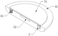
Preferably, telescopic rods are fixedly mounted on the upper surfaces of the sealing covers through grooves, weighing plates are fixedly mounted at the upper ends of the telescopic rods, pressure sensors are fixedly mounted on the upper surfaces of the sealing covers, pressure springs are fixedly mounted on the outer surfaces of the two telescopic rods, and the other ends of the pressure springs are fixedly mounted on the lower surfaces of the weighing plates;
through above-mentioned technical scheme, can bear the gravity of the waste material piece in the collection basket through weighing plate, transmit to pressure sensor, after gravity reachd the threshold value that pressure sensor set for, control the rotating electrical machines rotation, change and collect the basket.
Preferably, the crushing device comprises a connecting frame, the connecting frame is arranged below the turntable, a crusher shell is fixedly arranged on the outer surface of the connecting frame, a feed hopper is fixedly arranged on the upper surface of the crusher shell, a discharge conveying pipe is fixedly arranged on the lower surface of the crusher shell through a through hole, crushing rollers are rotatably connected to the inner wall of the crusher shell, two ends of the two crushing rollers penetrate through the outer surface of the crusher shell and then are fixedly arranged on the inner surface of the connecting frame through bearings, a driving motor is fixedly arranged on the outer surface of the connecting frame through a supporting plate, and the driving motor drives the two crushing rollers to synchronously rotate in opposite directions through a gear set;
through the technical scheme, the feed hopper is located below the collecting basket on one side, after the sealing cover of the collecting basket is opened, the waste material block can be conveyed into the feed hopper, the waste material block is crushed through the reverse rotation of the two crushing rollers, and the waste material block is output through the discharge conveying pipe.
Preferably, a limiting groove is formed in the crusher shell, sealing arc plates are inserted into two sides of the inner wall of the limiting groove in a sliding mode, rotary connecting plates are fixedly mounted at two ends of each sealing arc plate, and one end of each rotary connecting plate at one side is fixedly mounted on the outer surface of the crusher shell through a bearing;
through above-mentioned technical scheme, seal the junction of feeder hopper and breaker casing through rotatory even board, prevent that the dust that produces when the breakage from wafting to the air in to the workman in workshop cause the influence.
Preferably, one end of one of the rotary connecting plates is rotatably connected with the outer side surface of the crusher shell through a bearing, one end of the other rotary connecting plate is fixedly installed on the inner surface of one end of the connecting frame through a bearing, a toothed ring is fixedly installed on one end of the rotary connecting plate on the other side, a connecting seat is fixedly installed on the outer surface of one end of the connecting frame, two sides of the connecting seat are rotatably connected with transmission gears through bearings, the outer surfaces of the two transmission gears are meshed, the outer surfaces of the two transmission gears are respectively meshed with the inner walls of the two toothed rings, a control motor is fixedly installed on the outer surface of the connecting frame, and an output shaft of the control motor is fixedly installed on the outer surface of one toothed ring;
through above-mentioned technical scheme, the ring gear through control motor drive one side rotates, and the rotation of ring gear is through the transmission back of transmission gear, can drive another ring gear and carry out reverse rotation with fast for two sealed arc boards carry out relative or opposite slide at the spacing inslot, realize the work of opening and shutting, reach sealed effect.
Preferably, S1: after plastic shoe waste blocks to be treated are poured into a feeding hopper, the plastic shoe waste blocks fall onto a conveying belt through a discharge groove of the feeding hopper, the conveying belt is started, the conveying belt drives the stacked waste blocks to enter a guide plate, the splayed guide plate conveys the stacked waste blocks one by one, after the colors of the waste blocks are identified through an identification camera, a corresponding material pushing hydraulic cylinder is controlled to be started, a push plate is driven to push the waste blocks forwards, the waste blocks are located on one side of the upper surface of the conveying belt, the conveying belt is divided into two conveying areas by a sorting plate, and the waste blocks with different colors respectively enter two sides of the sorting plate;
s2: the waste material block enters the corresponding discharging hopper through the rotation of the conveying belt, and after entering the collecting basket through the discharging hopper, the waste material block is positioned on the weighing plate on the sealing cover, the pressure spring is compressed when the weighing plate is stressed, and after the telescopic rod is contracted, the weighing plate can press the lower pressure sensor;
s3: after the gravity of the materials in the collecting basket reaches a set threshold value, a rotating motor on the supporting seat is started to drive a half gear to rotate, the rotation of the half gear can drive the rotating gear to rotate 180 degrees, so that the collecting basket filled with the waste material blocks leaves the lower part of the conveying belt, another empty collecting basket is rotated to the lower part of the conveying belt, a roller of an empty collecting basket sealing cover is pressed by the lower surface of the concave ring after leaving the concave part of the concave ring, the sealing cover deflects to cover the lower part of the collecting basket, meanwhile, the roller of the sealing cover can rotate on the lower surface of the concave ring, after meeting the concave part of the lower surface of the concave ring, the sealing cover is reset under the action of a torsion spring to open the waste material blocks in the collecting basket, and the waste material blocks enter a feeding hopper below;
s4: control motor starts, drive the ring gear rotation of fixing with it, the ring gear is through the transmission back of two transmission gears, drive another ring gear and carry out reverse rotation, it takes place to deflect to drive rotatory even board, rotatory even board drives two sealed arc boards of spacing inslot and takes place relative movement, seal the junction of feeder hopper and breaker casing, driving motor on the link passes through two crushing roller rotations of gear train drive, smash the material in the breaker casing, the waste material piece after smashing passes through ejection of compact conveyer pipe output.
The beneficial effects of the invention are as follows:
1. through setting up sorting unit, can realize automatic separation, the mixed waste piece that will have two kinds of different colours is categorised, after discerning the colour through the discernment camera, control pushes away the material pneumatic cylinder and pushes the waste piece of different colours to corresponding one side, the sorting plate divides the conveyer belt into two conveying area territories, the waste piece of different colours is located the both sides of sorting plate respectively, thereby realize the classification to the waste piece, do not need the manual work to classify, it needs the manual work to classify to have solved current waste piece for the plastics shoes production and handle, work efficiency's technical problem has been reduced.
2. Through setting up conveyor, can carry out the ration to the waste material piece and carry smashing, when preventing that the crushing volume is too much, cause the load of rubbing crusher, be located the below of conveyer belt through collecting the basket, the waste material piece in the collection basket is through pressing down of symmetrical heavy plate, the gravity of the waste material piece in the weighing plate passes through the pressure sensor detection collection basket, after gravity reachs the threshold value of settlement, the carousel can rotate, drive the collection basket and rotate, the sealed lid of collecting the basket simultaneously can be opened and close automatically, reduce artificial input, thereby reduce the load to rubbing crusher, the life of rubbing crusher has been increased, it needs artifical adding in grades to have solved current waste material piece processing for the plastics shoes production, the technical problem of workman's work load has been increased.
3. Through setting up breaker, can carry out shredding to the waste material piece automatically, smash the in-process simultaneously and prevent that the dust from wafting out, under the start-up of control motor, two sealed arc boards carry out relative movement in the cooperation of ring gear and transmission gear, can seal the junction of feeder hopper and breaker casing, thereby can realize reducing the showy of dust, the floating dust that produces when having solved current waste material piece for plastics shoes production and handling crushing causes the influence to workman's health, cause the technical problem of pollution to the environment easily simultaneously.
Drawings
FIG. 1 is a schematic view of a waste block treating apparatus for plastic shoe production and a treating method thereof according to the present invention;
FIG. 2 is a perspective view of a conveyer belt structure of a waste block processing device for plastic shoe production and a processing method thereof according to the present invention;
FIG. 3 is a perspective view of a sorting plate structure of the apparatus and method for processing waste material blocks for plastic shoe production according to the present invention;
FIG. 4 is a perspective view of a supporting seat structure of the apparatus and method for processing waste material blocks for plastic shoe production according to the present invention;
FIG. 5 is a perspective view of a rotary gear structure of the apparatus and method for processing waste material blocks for plastic shoe production according to the present invention;
FIG. 6 is a perspective view of a half-gear structure of a waste block processing apparatus for plastic shoe production and a processing method thereof according to the present invention;
FIG. 7 is a perspective view of a collecting basket structure of the apparatus and method for processing waste material blocks for plastic shoe production according to the present invention;
FIG. 8 is a perspective view showing a sealing cap structure of a waste block treating apparatus for plastic shoe production and a method for treating the same according to the present invention;
FIG. 9 is a perspective view showing the structure of a pressure sensor of the apparatus for treating waste material blocks for plastic shoe production and the method for treating the same according to the present invention;
FIG. 10 is a perspective view of a telescopic rod structure of the apparatus and method for processing waste material blocks for plastic shoe production according to the present invention;
FIG. 11 is a perspective view of the structure of the crusher housing of the apparatus and the method for processing the waste material blocks for plastic shoe production according to the present invention;
FIG. 12 is a perspective view of a crushing roller structure of the apparatus for treating waste material blocks for plastic shoe production and the method thereof according to the present invention;
FIG. 13 is a perspective view of the structure of the discharging and conveying pipe of the apparatus and method for processing waste material blocks for plastic shoe production according to the present invention;
FIG. 14 is a perspective view of a sealing arc plate structure of a waste block processing device for plastic shoe production and a processing method thereof according to the present invention;
fig. 15 is a perspective view of a toothed ring structure of a waste block processing device for plastic shoe production and a processing method thereof according to the present invention.
In the figure: 1. a frame; 11. feeding a hopper; 2. a conveyor belt; 21. a baffle; 22. identifying a camera; 23. a material pushing hydraulic cylinder; 24. pushing the plate; 25. a sorting plate; 3. a supporting seat; 31. a support bar; 32. a turntable; 33. a rotating electric machine; 34. a half gear; 35. a limiting ring; 36. a rotating gear; 37. a limiting plate; 4. a collection basket; 41. a feeding hopper; 42. a sealing cover; 43. a torsion spring; 44. a roller; 45. a concave ring; 5. a telescopic rod; 51. a weighing plate; 52. a pressure sensor; 53. a pressure spring; 6. a connecting frame; 61. a crusher shell; 62. a feed hopper; 63. a discharge conveying pipe; 64. a crushing roller; 65. a drive motor; 7. a limiting groove; 71. sealing the arc plate; 72. rotating the connecting plate; 73. a toothed ring; 74. a connecting seat; 75. a transfer gear; 76. and controlling the motor.
Detailed Description
The technical solutions in the embodiments of the present invention will be clearly and completely described below with reference to the drawings in the embodiments of the present invention, and it is obvious that the described embodiments are only a part of the embodiments of the present invention, and not all of the embodiments.
Referring to fig. 1 to 15, a waste material block processing device for plastic shoe production and a processing method thereof include a frame 1 and a feeding hopper 11, wherein the feeding hopper 11 is fixedly installed on the outer surface of the frame 1, and further includes a sorting device, a conveying device and a crushing device installed on one side of the frame 1.
As shown in fig. 2-3, a sorting device is arranged at one side of the frame 1, and the sorting device sorts the waste material blocks to be processed and then transmits the waste material blocks to the conveying device;
the sorting device is arranged on one side of the frame 1, a conveying belt 2 is arranged on one side of the frame 1 for automatically conveying waste blocks, flow guide plates 21 are fixedly arranged on the outer surfaces of the racks on two sides of the conveying belt 2 for shunting, the two flow guide plates 21 are symmetrically distributed and then enclosed into a splayed shape, and a discharge chute of the feeding hopper 11 is positioned above one end of the conveying belt 2;
further, in order to identify the color of the waste material block, an identification camera 22 is fixedly installed on the outer surface of the rack of the conveyor belt 2 through a support frame, a color identification module is arranged on the identification camera 22, in order to automatically push the material, pushing hydraulic cylinders 23 are fixedly installed on two sides of the outer surface of the rack of the conveyor belt 2 through support plates, push plates 24 are fixedly installed at one ends of piston rods of the two pushing hydraulic cylinders 23, and in order to carry out classified conveying, a sorting plate 25 is fixedly installed at the other end of the conveyor belt 2 through a support frame.
As shown in fig. 4-10, the conveying device is located at one side of the sorting device, and conveys the waste material blocks sorted by the sorting device into the crushing device;
the conveying device is provided with two groups, the conveying device is arranged at one end of the conveying belt 2, the conveying device comprises a supporting seat 3, the supporting seat 3 is arranged at one side of the conveying belt 2, the supporting seat 3 consists of a base and a vertical column arranged on the upper surface of the base, a supporting rod 31 is fixedly arranged on the upper surface of the base of the supporting seat 3 through a bearing, a rotary table 32 is fixedly arranged at one end of the supporting rod 31 after penetrating through the interior of the supporting seat 3, the lower surface of the rotary table 32 and the upper surface of the vertical column of the supporting seat 3 are fixedly arranged through a bearing, a rotary motor 33 is fixedly arranged on the upper surface of the base of the supporting seat 3 in order to automatically drive the supporting rod 31 to rotate, a half gear 34 is fixedly arranged at one end of a conveying shaft of the rotary motor 33 in order to drive the rotary table 32 to rotate in an equal division manner, then a rotary gear 36 is fixedly arranged on the outer surface of the supporting rod 31, and the outer surface of the half gear 34 is meshed with the outer surface of the rotary gear 36, the number of teeth of the half gear 34 is equal to one half of the number of teeth of the rotary gear 36, in order to limit the support rod 31, a limit ring 35 is fixedly installed on the lower surface of the half gear 34, a limit plate 37 is fixedly installed on the lower surface of the rotary gear 36, and then both ends of the limit plate 37 are in sliding connection with the outer surface of the limit ring 35;
further, in order to collect waste material blocks, collecting baskets 4 are fixedly installed on two sides of the upper surface of the rotary table 32 through holes, in order to facilitate the waste material blocks to enter the collecting baskets 4, blanking hoppers 41 are fixedly installed on the upper surface of the collecting baskets 4, in order to facilitate the waste material blocks to enter and exit, a sealing cover 42 is hinged to one side of the lower surface of the collecting baskets 4 through a pin shaft, in order to facilitate the automatic resetting of the sealing cover 42, a torsion spring 43 is arranged at the hinged position of the sealing cover 42 and the collecting baskets 4, the upper surface of one end of the sealing cover 42 is rotatably connected with a roller 44 through a fixing frame, a concave ring 45 is fixedly installed on the outer surface of a stand column of the supporting seat 3, and then the outer surface of the roller 44 is rotatably connected with the outer surface of the concave ring 45 to control the sealing cover 42 to automatically open and close;
further, the telescopic rods 5 are fixedly installed on the upper surface of the sealing cover 42 through the grooves, the weighing plate 51 is fixedly installed at the upper end of the telescopic rods 5, the telescopic rods 5 limit the position of the weighing plate 51, in order to detect the weight of waste blocks in the collecting basket 4, the pressure sensor 52 is fixedly installed on the upper surface of the sealing cover 42, in order to facilitate the resetting of the weighing plate 51, the pressure springs 53 are fixedly installed on the outer surfaces of the two telescopic rods 5, and then the other ends of the pressure springs 53 are fixedly installed with the lower surface of the weighing plate 51.
As shown in fig. 11-15, the crushing device is located at one side of the sorting device, and the crushing device performs crushing work on the waste material blocks conveyed by the sorting device;
the crushing device is arranged on one side of the conveyor belt 2 and comprises a connecting frame 6, the connecting frame 6 is arranged below the turntable 32, a crushing shell 61 is fixedly arranged on the outer surface of the connecting frame 6, a feed hopper 62 is fixedly arranged on the upper surface of the crushing shell 61 for facilitating feeding, a discharge conveying pipe 63 is fixedly arranged on the lower surface of the crushing shell 61 through a through hole for facilitating discharging, crushing rollers 64 are rotatably connected to the inner wall of the crushing shell 61 for facilitating crushing, two ends of each of the two crushing rollers 64 penetrate through the outer surface of the crushing shell 61 and then are fixedly arranged on the inner surface of the connecting frame 6 through bearings for driving the crushing rollers 64 to rotate, a driving motor 65 is fixedly arranged on the outer surface of the connecting frame 6 through a supporting plate, one end of an output shaft of the driving motor 65 is fixedly arranged on one end of one crushing roller 64, and the driving motor 65 drives the two crushing rollers 64 to synchronously rotate in opposite directions through a gear set, the gear set comprises two meshed gears which are respectively and fixedly arranged at one end of the two crushing rollers 64;
furthermore, in order to seal the joint between the damaged shell and the feed hopper 62, a limit groove 7 is formed in the crusher shell 61, two sides of the inner wall of the limit groove 7 are slidably inserted with sealing arc plates 71, in order to drive the sealing arc plates 71 to move, rotary connecting plates 72 are fixedly mounted at two ends of the two sealing arc plates 71, and one end of each rotary connecting plate 72 close to one side of the driving motor 65 is fixedly mounted with a connecting shaft on the outer surface of the crusher shell 61 through a bearing;
further, one end of one rotary connecting plate 72 far away from the driving motor 65 is rotatably connected with the outer side surface of the crusher shell 61 through a bearing, one end of the other rotary connecting plate 72 is fixedly installed with the inner surface of one end of the connecting frame 6 through a bearing, in order to drive the two sealing arc plates 71 to rotate, a toothed ring 73 is fixedly arranged at one end of the rotary connecting plate 72 at the other side, a connecting seat 74 is fixedly arranged on the outer surface of one end of the connecting frame 6, in order to enable the two toothed rings 73 to rotate reversely at the same speed, on both sides of the connecting base 74, a transfer gear 75 is rotatably connected by a bearing, outer surfaces of the two transfer gears 75 are engaged, then, the outer surfaces of the two transfer gears 75 are engaged with the inner walls of the two ring gears 73, respectively, and, in order to drive the ring gears 73 to rotate automatically, a control motor 76 is fixedly arranged on the outer surface of the connecting frame 6, and an output shaft of the control motor 76 is fixedly arranged on the outer surface of one gear ring 73;
s1: after a plastic shoe waste block to be treated is poured into the feeding hopper 11, the waste block falls onto the conveying belt 2 through a discharging groove of the feeding hopper 11, the conveying belt 2 is started, the conveying belt 2 drives the accumulated waste block to enter the guide plate 21, the splayed guide plate 21 conveys the accumulated waste block one by one, after the color of the waste block is identified through the identification camera 22, the corresponding pushing hydraulic cylinder 23 is controlled to be started, the pushing plate 24 is driven to push the waste block forwards, the waste block is positioned on one side of the upper surface of the conveying belt 2, the conveying belt 2 is divided into two conveying areas by the sorting plate 25, and the waste blocks with different colors respectively enter two sides of the sorting plate 25;
s2: through the rotation of the conveyor belt 2, the waste material block enters the corresponding lower hopper 41, after entering the collection basket 4 through the lower hopper 41, the waste material block is positioned on the weighing plate 51 on the sealing cover 42, the pressure spring 53 is compressed when the weighing plate 51 is under pressure, and after the telescopic rod 5 is contracted, the weighing plate 51 can press the pressure sensor 52 below;
s3: after the gravity of the materials in the collecting basket 4 reaches a set threshold value, the rotating motor 33 on the supporting seat 3 is started to drive the half gear 34 to rotate, the rotation of the half gear 34 can drive the rotating gear 36 to rotate 180 degrees, so that the collecting basket 4 filled with waste materials leaves the lower part of the conveyor belt 2, another vacant collecting basket 4 is rotated to the lower part of the conveyor belt 2, the roller 44 of the vacant collecting basket 4 sealing cover 42 is pressed by the lower surface of the concave ring 45 after leaving the concave part of the concave ring 45, the sealing cover 42 deflects to cover the lower part of the collecting basket 4, the roller 44 of the sealing cover 42 can rotate on the lower surface of the concave ring 45, after meeting the concave part of the lower surface of the concave ring 45, the sealing cover 42 is reset under the action of the torsion spring 43 to open the waste materials in the collecting basket 4, and the waste materials enter the feeding hopper 62 below;
s4: the control motor 76 is started to drive the gear ring 73 fixed with the control motor to rotate, after the gear ring 73 is transmitted through the two transmission gears 75, the gear ring 73 drives the other gear ring 73 to rotate reversely, the rotary connecting plate 72 is driven to deflect, the rotary connecting plate 72 drives the two sealing arc plates 71 in the limiting groove 7 to move relatively, the connecting part of the feed hopper 62 and the crusher shell 61 is sealed, the driving motor 65 on the connecting frame 6 drives the two crushing rollers 64 to rotate through the gear set, materials in the crusher shell 61 are crushed, and the crushed waste materials are output through the discharge conveying pipe 63.
The working principle is as follows: after a plastic shoe waste block to be treated is poured into the feeding hopper 11, the plastic shoe waste block falls onto the conveying belt 2 through the discharging groove of the feeding hopper 11, the conveying belt 2 is started, the conveying belt 2 drives the accumulated waste block to enter the guide plate 21, the guide plate 21 in the shape of a Chinese character 'ba' carries out one-by-one conveying on the accumulated waste block, after the color of the waste block is identified through the identification camera 22, the corresponding material pushing hydraulic cylinder 23 is controlled to be started, the push plate 24 is driven to push the waste block forwards, the waste block is positioned on one side of the upper surface of the conveying belt 2, the conveying belt 2 is separated into two conveying areas by the sorting plate 25, and waste blocks with different colors respectively enter two sides of the sorting plate 25;
through the rotation of the conveyor belt 2, the waste material block enters the corresponding lower hopper 41, after entering the collection basket 4 through the lower hopper 41, the waste material block is positioned on the weighing plate 51 on the sealing cover 42, the pressure spring 53 is compressed when the weighing plate 51 is under pressure, and after the telescopic rod 5 is contracted, the weighing plate 51 can press the pressure sensor 52 below;
after the gravity of the material in the collecting basket 4 reaches a set threshold value, the rotating motor 33 on the supporting seat 3 is started to drive the half gear 34 to rotate, after the rotation of the half gear 34 can drive the rotating gear 36 to rotate 180 degrees, the limiting ring 35 rotates on the outer surface of the limiting plate 37, the supporting rod 31 drives the rotating disc 32 to rotate, so that after the collecting basket 4 filled with the waste material blocks leaves the lower part of the conveyor belt 2, the other empty collecting basket 4 is rotated to the lower part of the conveyor belt 2, the roller 44 of the sealing cover 42 on the empty collecting basket 4 leaves the concave part of the concave ring 45 and is pressed by the lower surface of the concave ring 45, the sealing cover 42 covers the lower part of the collecting basket 4 after deflecting, meanwhile, the roller 44 of the sealing cover 42 can rotate on the lower surface of the concave ring 45, after encountering the concave part of the lower surface of the concave ring 45, the sealing cover 42 resets and opens the waste material blocks in the collecting basket 4 under the action force of the torsion spring 43, the waste material block enters a feed hopper 62 below;
the control motor 76 is started to drive the gear ring 73 fixed with the control motor to rotate on the connecting frame 6, the gear ring 73 drives the transmission gear 75 meshed with the gear ring 73 to rotate, the transmission gear 75 drives the other transmission gear 75 meshed with the transmission gear to rotate on the connecting seat 74, so that the gear ring 73 meshed with the transmission gear rotates, after the transmission of the two transmission gears 75, the other gear ring 73 is driven to reversely rotate, the rotary connecting plate 72 deflects, the rotary connecting plate 72 drives the two sealing arc plates 71 in the limiting groove 7 to relatively move, the connecting part of the feed hopper 62 and the crusher shell 61 is sealed, the driving motor 65 on the connecting frame 6 drives the two crushing rollers 64 to reversely rotate through the gear set, waste blocks in the crusher shell 61 are crushed, and the crushed waste blocks are output through the discharge conveying pipe 63.
The above description is only for the preferred embodiment of the present invention, but the scope of the present invention is not limited thereto, and any person skilled in the art should be considered to be within the technical scope of the present invention, and the technical solutions and the inventive concepts thereof according to the present invention should be equivalent or changed within the scope of the present invention.
Claims (10)
1. The utility model provides a waste material piece processing apparatus is used in plastics shoes production, includes frame (1) and feeding funnel (11), feeding funnel (11) fixed mounting is in the surface of frame (1), its characterized in that: the device also comprises a sorting device, a conveying device and a crushing device which are arranged on one side of the frame (1);
the sorting device is positioned on one side of the frame (1), and the sorting device sorts waste blocks to be processed and then transmits the waste blocks to the conveying device;
the conveying device is positioned at one side of the sorting device and conveys the waste blocks classified by the sorting device into the crushing device;
the crushing device is positioned on one side of the sorting device and is used for crushing the waste blocks conveyed by the sorting device.
2. The apparatus for processing waste blocks for plastic shoe production as claimed in claim 1, wherein: sorting unit includes conveyer belt (2), conveyer belt (2) set up one side of frame (1), the both sides frame external fixed surface of conveyer belt (2) installs guide plate (21), two guide plate (21) enclose into eight characters shape after being the symmetric distribution, the blown down tank of feeding funnel (11) is located the one end top of conveyer belt (2).
3. The apparatus for processing waste blocks for plastic shoe production as claimed in claim 2, wherein: the frame surface of conveyer belt (2) has discernment camera (22) through support frame fixed mounting, the frame surface both sides of conveyer belt (2) all have through backup pad fixed mounting and push away material pneumatic cylinder (23), two the equal fixed mounting of piston rod one end that pushes away material pneumatic cylinder (23) has push pedal (24), the other end of conveyer belt (2) has sorting plate (25) through support frame fixed mounting.
4. The apparatus for processing waste blocks for plastic shoe production as claimed in claim 2, wherein: the conveying device is provided with two groups, the conveying device comprises a supporting seat (3), the supporting seat (3) is installed on one side of the conveying belt (2), a supporting rod (31) is fixedly installed on the upper surface of a base of the supporting seat (3) through a bearing, a turntable (32) is fixedly installed on the inner rear portion of the supporting seat (3) in a penetrating mode at one end of the supporting rod (31), the lower surface of the turntable (32) is fixedly installed on the upper surface of a stand column of the supporting seat (3) through the bearing, a rotating motor (33) is fixedly installed on the upper surface of the base of the supporting seat (3), a half gear (34) is fixedly installed at one end of a conveying shaft of the rotating motor (33), a limiting ring (35) is fixedly installed on the lower surface of the half gear (34), a rotating gear (36) is fixedly installed on the outer surface of the supporting rod (31), and the outer surface of the half gear (34) is meshed with the outer surface of the rotating gear (36), the lower surface fixed mounting of rotatory gear (36) has limiting plate (37), the both ends of limiting plate (37) all with the surface sliding connection of spacing ring (35).
5. The apparatus for processing waste blocks for plastic shoe production according to claim 4, wherein: the utility model discloses a material collecting device, including carousel (32), collection basket (4), hopper (41) under the last fixed surface of collection basket (4) installs, the lower surface one side of collection basket (4) articulates through the round pin axle has sealed lid (42), sealed lid (42) with the articulated department of collection basket (4) is provided with torsional spring (43), the one end upper surface of sealed lid (42) is connected with gyro wheel (44) through the mount rotation, the stand fixed surface of supporting seat (3) installs concave ring (45), the surface of gyro wheel (44) with the surface rotation of concave ring (45) is connected.
6. The apparatus for processing waste blocks for plastic shoe production according to claim 5, wherein: the upper surface of sealed lid (42) has telescopic link (5) through recess fixed mounting, the upper end fixed mounting of telescopic link (5) has weighing plate (51), the last fixed surface of sealed lid (42) installs pressure sensor (52), two the fixed surface of telescopic link (5) installs pressure spring (53), the other end of pressure spring (53) with the lower fixed surface installation of weighing plate (51).
7. The apparatus for processing waste blocks for plastic shoe production according to claim 4, wherein: the crushing device comprises a connecting frame (6), the connecting frame (6) is arranged below the rotary disc (32), a crusher shell (61) is fixedly arranged on the outer surface of the connecting frame (6), a feed hopper (62) is fixedly arranged on the upper surface of the crusher shell (61), a discharging conveying pipe (63) is fixedly arranged on the lower surface of the crusher shell (61) through a through hole, the inner wall of the crusher shell (61) is rotatably connected with crushing rollers (64), two ends of the two crushing rollers (64) penetrate through the outer surface of the crusher shell (61) and then are fixedly arranged with the inner surface of the connecting frame (6) through bearings, the outer surface of the connecting frame (6) is fixedly provided with a driving motor (65) through a supporting plate, the driving motor (65) drives the two crushing rollers (64) to synchronously rotate in opposite directions through a gear set.
8. The apparatus for processing waste blocks for plastic shoe production as claimed in claim 7, wherein: limiting grooves (7) are formed in the crusher shell (61), sealing arc plates (71) are inserted into two sides of the inner wall of each limiting groove (7) in a sliding mode, rotary connecting plates (72) are fixedly mounted at two ends of each sealing arc plate (71), and one end of each rotary connecting plate (72) is fixedly mounted on the outer surface of the crusher shell (61) through a bearing.
9. The apparatus for processing waste blocks for plastic shoe production as claimed in claim 8, wherein: one end of one rotary connecting plate (72) is rotatably connected with the outer side surface of the crusher shell (61) through a bearing, one end of the other rotary connecting plate (72) is fixedly arranged with the inner surface of one end of the connecting frame (6) through a bearing, one end of the other rotary connecting plate (72) is fixedly arranged with a toothed ring (73), a connecting seat (74) is fixedly arranged on the outer surface of one end of the connecting frame (6), two sides of the connecting seat (74) are rotatably connected with transfer gears (75) through bearings, the outer surfaces of the two transfer gears (75) are meshed, the outer surfaces of the two transfer gears (75) are respectively meshed with the inner walls of the two toothed rings (73), a control motor (76) is fixedly arranged on the outer surface of the connecting frame (6), an output shaft of the control motor (76) is fixedly arranged on the outer surface of one gear ring (73).
10. The processing method of the waste block processing apparatus for plastic shoe production according to any one of claims 1 to 9, comprising the steps of:
s1: after plastic shoe waste blocks to be treated are poured into a feeding hopper (11), the plastic shoe waste blocks fall onto a conveying belt (2) through a discharging groove of the feeding hopper (11), the conveying belt (2) is started, the conveying belt (2) drives the stacked waste blocks to enter a guide plate (21), the guide plate (21) in the shape of a Chinese character 'ba' conveys the stacked waste blocks one by one, after the colors of the waste blocks are identified through an identification camera (22), a corresponding material pushing hydraulic cylinder (23) is controlled to be started, a push plate (24) is driven to push the waste blocks forwards, the waste blocks are positioned on one side of the upper surface of the conveying belt (2), the conveying belt (2) is divided into two conveying areas by a sorting plate (25), and waste blocks with different colors respectively enter two sides of the sorting plate (25);
s2: the waste material blocks enter the corresponding discharging hoppers (41) through the rotation of the conveying belt (2), after entering the collecting basket (4) through the discharging hoppers (41), the waste material blocks are positioned on the weighing plates (51) on the sealing covers (42), the weighing plates (51) compress the pressure springs (53) when being pressed, and after the telescopic rods (5) are contracted, the weighing plates (51) can press the pressure sensors (52) below;
s3: after the gravity of the materials in the collecting basket (4) reaches a set threshold value, a rotating motor (33) on a supporting seat (3) is started to drive a half gear (34) to rotate, the rotation of the half gear (34) can drive a rotating gear (36) to rotate 180 degrees, so that the collecting basket (4) filled with waste materials leaves the lower part of a conveyor belt (2), another empty collecting basket (4) is rotated to the lower part of the conveyor belt (2), a roller (44) of a sealing cover (42) of the empty collecting basket (4) is pressed by the lower surface of a concave ring (45) after leaving the concave part of the concave ring (45), the sealing cover (42) covers the lower part of the collecting basket (4) after deflecting, the roller (44) of the sealing cover (42) can rotate on the lower surface of the concave ring (45), and after meeting the concave part of the lower surface of the concave ring (45), the sealing cover (42) is reset under the action force of a torsion spring (43) to open the waste materials in the collecting basket (4), the waste material block enters a feed hopper (62) below;
s4: control motor (76) starts, drive ring gear (73) fixed with it and rotate, ring gear (73) are through the transmission back of two transmission gears (75), drive another ring gear (73) and carry out reverse rotation, it deflects to drive rotatory even board (72), rotatory even board (72) drive two sealed arc boards (71) in spacing groove (7) and take place relative movement, seal the junction of feeder hopper (62) and breaker casing (61), driving motor (65) on link (6) drive two crushing roller (64) through the gear train and rotate, smash the material in breaker casing (61), the waste material piece after smashing exports through ejection of compact conveyer pipe (63).
Priority Applications (1)
| Application Number | Priority Date | Filing Date | Title |
|---|---|---|---|
| CN202210194084.1A CN114603751A (en) | 2022-03-01 | 2022-03-01 | Waste material block treatment device for plastic shoe production and treatment method thereof |
Applications Claiming Priority (1)
| Application Number | Priority Date | Filing Date | Title |
|---|---|---|---|
| CN202210194084.1A CN114603751A (en) | 2022-03-01 | 2022-03-01 | Waste material block treatment device for plastic shoe production and treatment method thereof |
Publications (1)
| Publication Number | Publication Date |
|---|---|
| CN114603751A true CN114603751A (en) | 2022-06-10 |
Family
ID=81860832
Family Applications (1)
| Application Number | Title | Priority Date | Filing Date |
|---|---|---|---|
| CN202210194084.1A Pending CN114603751A (en) | 2022-03-01 | 2022-03-01 | Waste material block treatment device for plastic shoe production and treatment method thereof |
Country Status (1)
| Country | Link |
|---|---|
| CN (1) | CN114603751A (en) |
Citations (5)
| Publication number | Priority date | Publication date | Assignee | Title |
|---|---|---|---|---|
| CN104890143A (en) * | 2015-06-10 | 2015-09-09 | 河北吉悦再生物资回收有限公司 | Production technology capable of utilizing PET waste plastics for producing bottle purifying pieces for fibrous raw materials |
| CN105312255A (en) * | 2015-11-26 | 2016-02-10 | 森蓝环保(上海)有限公司 | Automatic separation equipment of waste mixed plastics and method thereof |
| CN105643833A (en) * | 2014-11-14 | 2016-06-08 | 镇江凯天工艺品有限公司 | Plastic recovery process for waste plastic toys |
| CN106426643A (en) * | 2016-08-29 | 2017-02-22 | 上海交通大学 | Method for sorting broken plastics in waste household appliances through near infrared absorption spectroscopy analysis device |
| CN112079004A (en) * | 2020-07-17 | 2020-12-15 | 兰州理工大学 | Automatic beverage bottle recycling machine |
-
2022
- 2022-03-01 CN CN202210194084.1A patent/CN114603751A/en active Pending
Patent Citations (5)
| Publication number | Priority date | Publication date | Assignee | Title |
|---|---|---|---|---|
| CN105643833A (en) * | 2014-11-14 | 2016-06-08 | 镇江凯天工艺品有限公司 | Plastic recovery process for waste plastic toys |
| CN104890143A (en) * | 2015-06-10 | 2015-09-09 | 河北吉悦再生物资回收有限公司 | Production technology capable of utilizing PET waste plastics for producing bottle purifying pieces for fibrous raw materials |
| CN105312255A (en) * | 2015-11-26 | 2016-02-10 | 森蓝环保(上海)有限公司 | Automatic separation equipment of waste mixed plastics and method thereof |
| CN106426643A (en) * | 2016-08-29 | 2017-02-22 | 上海交通大学 | Method for sorting broken plastics in waste household appliances through near infrared absorption spectroscopy analysis device |
| CN112079004A (en) * | 2020-07-17 | 2020-12-15 | 兰州理工大学 | Automatic beverage bottle recycling machine |
Similar Documents
| Publication | Publication Date | Title |
|---|---|---|
| CN201337987Y (en) | Fresh and dried fruit grader | |
| CN111112120A (en) | Asparagus grader | |
| CN201046439Y (en) | Rotary feeding-discharging measuring device | |
| CN113443238B (en) | Agricultural product packaging machine | |
| CN110884810A (en) | Garbage recycling automatic classification, compression, storage and transfer equipment | |
| CN112371698A (en) | Civil engineering classification device | |
| CN213103313U (en) | Storage box equipment | |
| CN113356169B (en) | River garbage collection treatment facility is used in municipal administration | |
| CN104998830B (en) | A kind of rubbish conveys sorting equipment | |
| CN114603751A (en) | Waste material block treatment device for plastic shoe production and treatment method thereof | |
| CN212041539U (en) | Asparagus grader | |
| CN211363613U (en) | Electric automatization industrial waste material baling equipment | |
| CN211100234U (en) | Precision image acquisition and sorting equipment | |
| CN216880502U (en) | Grinding machine self-detection material-distributing and waste-discharging mechanism | |
| JPH05177397A (en) | Method and device for automatically compressing empty can | |
| CN111085327A (en) | Biomass pellet fuel production line | |
| CN210850946U (en) | System is got rid of to slice class environmental protection regeneration polyethylene plastics impurity | |
| CN107103687A (en) | Waste product automated transaction machine | |
| KR102123420B1 (en) | Shredding and Drying Integrated Type Solid Fuel Manufacturing Equipment Using Recycled Waste | |
| CN219468866U (en) | Light matter quick packing equipment for solid waste screening | |
| CN111375471A (en) | Centralized treatment method for printing wastes | |
| CN220514800U (en) | Feeding device of color sorter | |
| CN212023135U (en) | Collection device of heavy calcium carbonate powder | |
| CN117129298B (en) | Plant quarantine equipment for efficiently dehydrating samples | |
| CN218610467U (en) | Salt look selection machine |
Legal Events
| Date | Code | Title | Description |
|---|---|---|---|
| PB01 | Publication | ||
| PB01 | Publication | ||
| SE01 | Entry into force of request for substantive examination | ||
| SE01 | Entry into force of request for substantive examination |