CN114570648A - Agricultural seeder with seed screening and removing structure and using method thereof - Google Patents
Agricultural seeder with seed screening and removing structure and using method thereof Download PDFInfo
- Publication number
- CN114570648A CN114570648A CN202210197893.8A CN202210197893A CN114570648A CN 114570648 A CN114570648 A CN 114570648A CN 202210197893 A CN202210197893 A CN 202210197893A CN 114570648 A CN114570648 A CN 114570648A
- Authority
- CN
- China
- Prior art keywords
- fertilizer
- screening
- box
- discharging
- plate
- Prior art date
- Legal status (The legal status is an assumption and is not a legal conclusion. Google has not performed a legal analysis and makes no representation as to the accuracy of the status listed.)
- Pending
Links
- 238000012216 screening Methods 0.000 title claims abstract description 58
- 238000000034 method Methods 0.000 title claims abstract description 24
- 239000003337 fertilizer Substances 0.000 claims abstract description 63
- 239000000463 material Substances 0.000 claims abstract description 59
- 238000007599 discharging Methods 0.000 claims abstract description 39
- 238000010899 nucleation Methods 0.000 claims description 9
- 238000007664 blowing Methods 0.000 claims description 6
- 238000013016 damping Methods 0.000 claims description 5
- 230000002787 reinforcement Effects 0.000 claims description 3
- 210000001503 joint Anatomy 0.000 claims description 2
- 235000017166 Bambusa arundinacea Nutrition 0.000 claims 3
- 235000017491 Bambusa tulda Nutrition 0.000 claims 3
- 241001330002 Bambuseae Species 0.000 claims 3
- 235000015334 Phyllostachys viridis Nutrition 0.000 claims 3
- 239000011425 bamboo Substances 0.000 claims 3
- 230000000712 assembly Effects 0.000 claims 2
- 238000000429 assembly Methods 0.000 claims 2
- 238000009434 installation Methods 0.000 claims 1
- 238000005096 rolling process Methods 0.000 description 4
- 230000000694 effects Effects 0.000 description 3
- 238000010586 diagram Methods 0.000 description 2
- 230000003014 reinforcing effect Effects 0.000 description 2
- 244000025254 Cannabis sativa Species 0.000 description 1
- 229920000742 Cotton Polymers 0.000 description 1
- 240000008042 Zea mays Species 0.000 description 1
- 235000005824 Zea mays ssp. parviglumis Nutrition 0.000 description 1
- 235000002017 Zea mays subsp mays Nutrition 0.000 description 1
- 230000009286 beneficial effect Effects 0.000 description 1
- 235000005822 corn Nutrition 0.000 description 1
- 238000005516 engineering process Methods 0.000 description 1
- 238000012986 modification Methods 0.000 description 1
- 230000004048 modification Effects 0.000 description 1
- 238000009331 sowing Methods 0.000 description 1
Images


Classifications
-
- B—PERFORMING OPERATIONS; TRANSPORTING
- B07—SEPARATING SOLIDS FROM SOLIDS; SORTING
- B07B—SEPARATING SOLIDS FROM SOLIDS BY SIEVING, SCREENING, SIFTING OR BY USING GAS CURRENTS; SEPARATING BY OTHER DRY METHODS APPLICABLE TO BULK MATERIAL, e.g. LOOSE ARTICLES FIT TO BE HANDLED LIKE BULK MATERIAL
- B07B9/00—Combinations of apparatus for screening or sifting or for separating solids from solids using gas currents; General arrangement of plant, e.g. flow sheets
-
- A—HUMAN NECESSITIES
- A01—AGRICULTURE; FORESTRY; ANIMAL HUSBANDRY; HUNTING; TRAPPING; FISHING
- A01C—PLANTING; SOWING; FERTILISING
- A01C15/00—Fertiliser distributors
- A01C15/12—Fertiliser distributors with movable parts of the receptacle
-
- B—PERFORMING OPERATIONS; TRANSPORTING
- B07—SEPARATING SOLIDS FROM SOLIDS; SORTING
- B07B—SEPARATING SOLIDS FROM SOLIDS BY SIEVING, SCREENING, SIFTING OR BY USING GAS CURRENTS; SEPARATING BY OTHER DRY METHODS APPLICABLE TO BULK MATERIAL, e.g. LOOSE ARTICLES FIT TO BE HANDLED LIKE BULK MATERIAL
- B07B1/00—Sieving, screening, sifting, or sorting solid materials using networks, gratings, grids, or the like
- B07B1/28—Moving screens not otherwise provided for, e.g. swinging, reciprocating, rocking, tilting or wobbling screens
- B07B1/34—Moving screens not otherwise provided for, e.g. swinging, reciprocating, rocking, tilting or wobbling screens jigging or moving to-and-fro perpendicularly or approximately perpendiculary to the plane of the screen
- B07B1/343—Moving screens not otherwise provided for, e.g. swinging, reciprocating, rocking, tilting or wobbling screens jigging or moving to-and-fro perpendicularly or approximately perpendiculary to the plane of the screen with mechanical drive elements other than electromagnets
-
- B—PERFORMING OPERATIONS; TRANSPORTING
- B07—SEPARATING SOLIDS FROM SOLIDS; SORTING
- B07B—SEPARATING SOLIDS FROM SOLIDS BY SIEVING, SCREENING, SIFTING OR BY USING GAS CURRENTS; SEPARATING BY OTHER DRY METHODS APPLICABLE TO BULK MATERIAL, e.g. LOOSE ARTICLES FIT TO BE HANDLED LIKE BULK MATERIAL
- B07B1/00—Sieving, screening, sifting, or sorting solid materials using networks, gratings, grids, or the like
- B07B1/42—Drive mechanisms, regulating or controlling devices, or balancing devices, specially adapted for screens
-
- B—PERFORMING OPERATIONS; TRANSPORTING
- B07—SEPARATING SOLIDS FROM SOLIDS; SORTING
- B07B—SEPARATING SOLIDS FROM SOLIDS BY SIEVING, SCREENING, SIFTING OR BY USING GAS CURRENTS; SEPARATING BY OTHER DRY METHODS APPLICABLE TO BULK MATERIAL, e.g. LOOSE ARTICLES FIT TO BE HANDLED LIKE BULK MATERIAL
- B07B1/00—Sieving, screening, sifting, or sorting solid materials using networks, gratings, grids, or the like
- B07B1/46—Constructional details of screens in general; Cleaning or heating of screens
-
- B—PERFORMING OPERATIONS; TRANSPORTING
- B07—SEPARATING SOLIDS FROM SOLIDS; SORTING
- B07B—SEPARATING SOLIDS FROM SOLIDS BY SIEVING, SCREENING, SIFTING OR BY USING GAS CURRENTS; SEPARATING BY OTHER DRY METHODS APPLICABLE TO BULK MATERIAL, e.g. LOOSE ARTICLES FIT TO BE HANDLED LIKE BULK MATERIAL
- B07B4/00—Separating solids from solids by subjecting their mixture to gas currents
- B07B4/08—Separating solids from solids by subjecting their mixture to gas currents while the mixtures are supported by sieves, screens, or like mechanical elements
-
- Y—GENERAL TAGGING OF NEW TECHNOLOGICAL DEVELOPMENTS; GENERAL TAGGING OF CROSS-SECTIONAL TECHNOLOGIES SPANNING OVER SEVERAL SECTIONS OF THE IPC; TECHNICAL SUBJECTS COVERED BY FORMER USPC CROSS-REFERENCE ART COLLECTIONS [XRACs] AND DIGESTS
- Y02—TECHNOLOGIES OR APPLICATIONS FOR MITIGATION OR ADAPTATION AGAINST CLIMATE CHANGE
- Y02P—CLIMATE CHANGE MITIGATION TECHNOLOGIES IN THE PRODUCTION OR PROCESSING OF GOODS
- Y02P60/00—Technologies relating to agriculture, livestock or agroalimentary industries
- Y02P60/20—Reduction of greenhouse gas [GHG] emissions in agriculture, e.g. CO2
Abstract
The invention discloses an agricultural seeder with a seed screening and removing structure and a using method thereof. According to the agricultural seeder with the seed screening and rejecting structure and the using method of the agricultural seeder, screened fertilizer is discharged into an inner cavity of a material box through a discharging box, the fertilizer is discharged through a discharging connecting seat arranged at the position of a built-in inclined plate, the discharged fertilizer enters a disc distributor through the discharging connecting seat, the rotating shaft is controlled to rotate at the moment, the fertilizer at the position of the disc distributor is scattered, and the scattered and discharged fertilizer is discharged to the ground through a material guide pipe II.
Description
Technical Field
The invention relates to the field of seeders, in particular to an agricultural seeder with a seed screening and removing structure and a use method thereof.
Background
A planting machine for a planter uses crop seeds as planting objects. The seeder for a certain kind or a certain crop is often named by the crop kind, such as a grain drill, a corn hill planter, a cotton seeder, a grass seeder, etc.
However, in the prior art, seeds need to be screened in the seeding process of the seeds, qualified seeds are screened out and sowed, and the conventional operation method is to perform split operation on the sowed seeds and the screened seeds, so that the time consumption of seed carrying is consumed in a certain sense, the structure is not optimized, and the design is not reasonable enough.
Disclosure of Invention
The invention aims to provide an agricultural seeder with a seed screening and removing structure and a use method thereof, and aims to solve the problems in the background technology.
In order to achieve the purpose, the invention provides the following technical scheme:
an agricultural seeder with a seed screening and rejecting structure and a using method thereof comprise a feed box, wherein a sorter is installed at the top end of the feed box, supporting blocks are installed on the left side and the right side of the feed box respectively, a frame assembly is welded on the lower surface of each supporting block, a roller is installed at the power end of the frame assembly, a wave wheel is arranged behind the roller, clamping pieces are fixedly connected to the left side and the right side of the back surface of a cross beam of the frame assembly respectively, a supporting column is installed at one end of the roller, a material pressing disc is installed on one side of the bottom end of the supporting column, a supporting table is fixedly connected to the top end of the supporting column, a material discharging connecting seat is installed at the material discharging end of the feed box, a disc distributor is fixedly connected to one end of the material discharging connecting seat, a material guide pipe II is installed at the bottom end of the disc distributor, a material guide pipe I is arranged on one side of the material guide pipe II, and a rotating shaft center part of the disc distributor is provided with a rotating shaft, the table top of the support table is provided with a motor, the driving end of the motor is fixedly arranged at one end of the rotating shaft, and the front end of the frame assembly is provided with a connecting piece.
As a still further scheme of the invention: the bottom fixedly connected with reinforcement seat of workbin, the position is installed with built-in swash plate about the inner chamber of workbin, the position has been seted up to the perforation in the subsurface of built-in swash plate, and to the through-hole butt joint of perforation and ejection of compact connecting seat, the bottom fixedly connected with reinforcement seat of workbin.
As a still further scheme of the invention: the back of the material guide pipe II is provided with a damping spring, and the middle part of the frame is provided with a damping spring.
As a still further scheme of the invention: the upper parts of the left side and the right side of the inner cavity of the material box are respectively provided with a material distributing rod, one end of each material distributing rod is provided with a connecting shaft, and the connecting shafts are rotatably connected with the axes of the wave wheels.
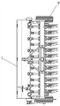
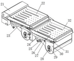
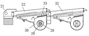
As a still further scheme of the invention: the material outlet box is installed at the discharge end of the sorting machine, the first screening plate is installed at the feed end of the material outlet box, the second screening plate is arranged on one side of the first screening plate, and shaft rods are fixedly connected to the upper surfaces of the first screening plate and the second screening plate.
As a still further scheme of the invention: the lower part of the first screening plate is provided with a side plate, a leaf cylinder is installed at the lower surface of the side plate close to the rear part, a positioning block is installed at the axis position of the leaf cylinder, a rotating shaft is installed at the axis position of the positioning block, and a through hole plate is installed at the air blowing end of the upper surface of the leaf cylinder.
As a still further scheme of the invention: the left and right sides of the lower surfaces of the two screening plates are welded with brackets, shaft rods are installed on the outer walls of the brackets, connecting rods are installed at one ends of the shaft rods, shaft rings are fixedly connected to the bottom ends of the connecting rods, supporting legs are arranged behind the shaft rings, and one ends of the supporting legs are fixedly installed on the outer walls of the brackets through connecting shafts.
As a still further scheme of the invention: the device comprises the following steps:
s1: fertilizer is added through the position on the sorter, and the control shaft circle rotates this moment, and the axostylus axostyle that the connecting rod of connection in shaft circle one end and connecting rod top are connected will rotate, and two screening boards that axostylus axostyle one end is connected play undulant effect from top to bottom to the realization is screened the fertilizer on the second screening board.
And S2, connecting the vane cylinder at one end of the separator with the positioning block, connecting the positioning block, and connecting the rotating shaft connected with the center part of the positioning block with the motor for rotation, thereby realizing the rotation of the rotating shaft, and simultaneously, the vanes connected with the middle part of the outer wall of the rotating shaft can roll the gas.
And S3, discharging the gas from the through hole plate part, blowing out the low-quality fertilizer in the fertilizer of the second screening plate, discharging the screened fertilizer through the discharge box, and feeding the fertilizer discharged from the discharge box to the upper part of the feed box to rotate by the operation of the impeller so as to realize the rolling input of the fertilizer at the feeding part of the feed box into the inner cavity of the feed box.
And S4, discharging the sieved fertilizer into an inner cavity of a material box through a discharge box, discharging the fertilizer through a discharge connecting seat arranged at the position of a built-in inclined plate, feeding the discharged fertilizer into a disc distributor through the discharge connecting seat, controlling the rotating shaft to rotate at the moment, distributing the fertilizer at the position of the disc distributor, and discharging the distributed fertilizer onto the ground through a material guide pipe II.
Compared with the prior art, the invention has the beneficial effects that:
in the invention, fertilizer is added through the upper part of the sorting machine, the shaft ring is controlled to rotate at the moment, the connecting rod connected with one end of the shaft ring and the shaft rod connected with the top end of the connecting rod rotate, the screening plate II connected with one end of the shaft rod plays a role of fluctuating up and down, so that the fertilizer on the screening plate II is screened, then the blade cylinder connected with one end of the sorting machine is matched with the upper positioning block for connecting the positioning block, meanwhile, the rotating shaft connected with the central part of the positioning block is matched with the upper motor to rotate, so that the rotating shaft is rotated, simultaneously, the blades connected with the middle part of the outer wall of the rotating shaft roll the gas, so that the gas is discharged from the through hole plate part and blows off the low quality of the fertilizer in the screening plate II, the screened fertilizer is discharged through the discharging box, and the fertilizer discharged from the discharging box to the upper part of the feed box is operated by the impeller, will reach and divide the material pole to rotate to realize rolling input the workbin inner chamber with workbin feeding position fertilizer, its structure is optimized more, the design is more reasonable.
According to the invention, the screened fertilizer is discharged into the inner cavity of the material box through the discharge box, the fertilizer is discharged from the discharge connecting seat arranged at the position of the built-in inclined plate, the discharged fertilizer enters the disc distributor through the discharge connecting seat, the rotating shaft is controlled to rotate at the moment, the fertilizer at the position of the disc distributor is scattered, and the scattered fertilizer is discharged to the ground through the material guide pipe II.
Drawings
FIG. 1 is a schematic structural diagram of an agricultural seeder with a seed screening and removing structure and a use method thereof.
FIG. 2 is a rear view of a material box in an agricultural seeder with a seed screening and removing structure and a use method thereof.
FIG. 3 is a side view of a bin and a sorter in an agricultural planter with seed culling structure and method of use.
Fig. 4 is a top plan view of an agricultural planter with seed screening and removal features and method of use thereof.
Fig. 5 is a structural diagram of a seed screening and removing structure of an agricultural seeding machine and a separator in the using method thereof.
Fig. 6 is a sectional view of a seed sowing machine with a seed screening and removing structure and a separator in a using method thereof.
In the figure: the material box comprises a material box 1, a sorting machine 2, a discharge connecting seat 3, a disc distributor 4, a rotating shaft 5, a supporting table 6, a supporting column 7, a clamping piece 8, a frame assembly 9, a first material guide pipe 10, a roller 11, an impeller 12, a connecting piece 13, a built-in inclined plate 14, a second material guide pipe 15, a damping spring 16, a material pressing disc 17, a supporting frame 18, a reinforcing seat 19, a material distributing rod 20, a material discharging box 21, a first screening plate 22, a side plate 23, supporting legs 24, a shaft ring 25, a connecting rod 26, a shaft rod 27, a rotating shaft 28, a positioning block 29, a blade cylinder 30, a supporting frame 31, a second screening plate 32 and a through hole plate 33.
Detailed Description
The technical solutions in the embodiments of the present invention will be clearly and completely described below with reference to the drawings in the embodiments of the present invention, and it is obvious that the described embodiments are only a part of the embodiments of the present invention, and not all of the embodiments. All other embodiments, which can be derived by a person skilled in the art from the embodiments given herein without making any creative effort, shall fall within the protection scope of the present invention.
Referring to fig. 1 to 6, in the embodiment of the invention, an agricultural seeder with a seed screening and rejecting structure and a using method thereof comprise a feed box 1, a sorting machine 2 is installed at the top end of the feed box 1, supporting blocks are installed on the left side and the right side of the feed box 1, a frame assembly 9 is welded on the lower surface of each supporting block, a roller 11 is installed at the power end of each frame assembly 9, a wave wheel 12 is arranged behind each roller 11, clamping members 8 are fixedly connected on the left side and the right side of the back surface of a cross beam of each frame assembly 9, a supporting column 7 is installed at one end of each roller 11, a material pressing disc 17 is installed at one side of the bottom end of each supporting column 7, a supporting table 6 is fixedly connected at the top end of each supporting column 7, a material discharging connecting seat 3 is installed at the discharging end of the feed box 1, a distributor 4 is fixedly connected at one end of each material distributing device 4, a material guiding pipe 15 is installed at one side of each material guiding pipe 10, a rotating shaft 5 is arranged at the axis part of the disc separator 4, a motor is arranged on the table top of the supporting table 6, the driving end of the motor is fixedly arranged with one end of the rotating shaft 5, a connecting piece 13 is arranged at the front end of a frame assembly 9, a built-in inclined plate 14 is arranged at the lower part of the left side and the right side of the inner cavity of the material box 1, the lower part of the surface of the built-in inclined plate 14 is provided with a through hole which is butted with a through hole of the discharging connecting seat 3, a reinforcing seat 19 is fixedly connected with the bottom end of the material box 1, a 34 is arranged on the back surface of a material guide pipe II 15, a damping spring 16 is arranged at the middle part of a frame of the 34, a material distributing rod 20 is arranged at the upper part of the left side and the right side of the inner cavity of the material box 1, a connecting shaft is arranged at one end of the material distributing rod 20 and is rotatably connected with the axis of a wave wheel 12, a material discharging box 21 is arranged at the discharging end of the material discharging box 21, a first screening plate 22 is arranged at the feeding end of the first screening plate 22, shaft rods 27 are fixedly connected to the upper surfaces of the first screening plate 22 and the second screening plate 32, a side plate 23 is arranged below the first screening plate 22, a leaf cylinder 30 is arranged at the position, close to the rear, of the lower surface of the side plate 23, a positioning block 29 is arranged at the shaft center of the leaf cylinder 30, a rotating shaft 28 is arranged at the shaft center of the positioning block 29, a through hole plate 33 is arranged at the air blowing end of the upper surface of the leaf cylinder 30, brackets 31 are welded to the left side and the right side of the lower surface of the second screening plate 32, the shaft rods 27 are arranged on the outer wall of the brackets 31, a connecting rod 26 is arranged at one end of each shaft rod 27, a shaft ring 25 is fixedly connected to the bottom end of each connecting rod 26, supporting legs 24 are arranged behind the shaft ring 25, and one ends of the supporting legs 24 are fixedly connected with the outer walls of the brackets 31 through connecting shafts;
the device comprises the following steps:
s1: the position is added on fertilizer passes through sorter 2, and control shaft collar 25 rotated this moment, and the axostylus axostyle 27 that the connecting rod 26 and the connecting rod 26 top of connecting at shaft collar 25 one end are connected will rotate, and two 32 screening boards that axostylus axostyle 27 one end is connected play undulant effect from top to bottom to the realization is screened the fertilizer on two 32 screening boards.
S2, the vane cylinder 30 connected to one end of the separator 2 is matched with the positioning block 29 to connect the positioning block 29, and the rotating shaft 28 connected to the central part of the positioning block 29 is matched with the motor to rotate, so that the rotating shaft 28 rotates, and the vanes connected to the middle part of the outer wall of the rotating shaft 28 roll the gas.
S3, discharging the air from the through hole plate 33 and blowing out the low-quality fertilizer in the fertilizer of the second screening plate 32, discharging the screened fertilizer through the discharge box 21, and rotating the fertilizer discharged from the discharge box 21 to the upper part of the feed box 1 by the operation of the impeller 12 until the fertilizer reaches the material distributing rod 20 and is input into the inner cavity of the feed box 1 in a rolling manner at the feeding part of the feed box 1.
S4, discharging the sieved fertilizer into an inner cavity of the feed box 1 through the discharge box 21, discharging the fertilizer through the discharge connecting seat 3 arranged at the position of the built-in inclined plate 14, feeding the discharged fertilizer into the disc distributor 4 through the discharge connecting seat 3, controlling the rotating shaft 5 to rotate at the moment, distributing the fertilizer at the position of the disc distributor 4, and discharging the distributed fertilizer onto the ground through the material guide pipe II 15.
The working principle of the invention is as follows: fertilizer is added through the upper part of the separator 2, the control shaft ring 25 rotates at the moment, the connecting rod 26 connected to one end of the shaft ring 25 and the shaft rod 27 connected to the top end of the connecting rod 26 rotate, the screening plate II 32 connected to one end of the shaft rod 27 has the effect of fluctuating up and down, so that the fertilizer on the screening plate II 32 is screened, then the vane cylinder 30 connected to one end of the separator 2 is matched with the positioning block 29 for connecting the positioning block 29, meanwhile, the rotating shaft 28 connected to the central part of the positioning block 29 is matched with the motor for rotating, so that the rotating shaft 28 rotates, meanwhile, the vane connected to the middle part of the outer wall of the rotating shaft 28 rolls the gas, so that the gas can be discharged from the through-hole plate 33 part and blows out the low quality fertilizer in the screening plate II 32, the screened fertilizer can be discharged through the discharging box 21, the fertilizer discharged from the discharging box 21 to the upper part of the feed box 1 can reach the material distributing rod 20 to rotate under the operation of the impeller 12, and the fertilizer at the feeding part of the feed box 1 is input into the inner cavity of the feed box 1 in a rolling manner;
the sieved fertilizer is discharged into the inner cavity of the material box 1 through the material discharging box 21, the fertilizer is discharged from the material discharging connecting seat 3 arranged at the position of the built-in inclined plate 14, the discharged fertilizer enters the disc distributor 4 through the material discharging connecting seat 3, the rotating shaft 5 is controlled to rotate at the moment, the fertilizer at the position of the disc distributor 4 is scattered, and the scattered and discharged fertilizer is discharged to the ground through the material guide pipe II 15.
Although the present invention has been described in detail with reference to the foregoing embodiments, it will be apparent to those skilled in the art that modifications may be made to the embodiments described in the foregoing embodiments, or equivalents may be substituted for elements thereof.
Claims (8)
1. The utility model provides an agricultural seeder and application method with seed screening rejects structure, includes workbin (1), its characterized in that: the sorting machine is characterized in that the sorting machine (2) is installed at the top end of the material box (1), supporting blocks are installed on the left side and the right side of the material box (1), frame assemblies (9) are welded on the lower surfaces of the supporting blocks, idler wheels (11) are installed at power ends of the frame assemblies (9) concerned, impellers (12) are arranged at the rear sides of the idler wheels (11), clamping pieces (8) are fixedly connected to the left side and the right side of the back of a beam of each frame assembly (9), supporting columns (7) are installed at one ends of the idler wheels (11), material pressing discs (17) are installed on one sides of the bottoms of the supporting columns (7), supporting tables (6) are fixedly connected to the top ends of the supporting columns (7), discharge connecting seats (3) are installed at the discharge ends of the material box (1), plate dividers (4) are fixedly connected to one ends of the discharge connecting seats (3), and guide pipes (15) are installed at the bottoms of the plate dividers (4), one side of the second material guide pipe (15) is provided with a first material guide pipe (10), a rotating shaft (5) is installed at the shaft center part of the plate distributor (4), a motor is installed on the table top of the supporting table (6), the driving end of the motor is fixedly installed with one end of the rotating shaft (5), and a connecting piece (13) is installed at the front end of the frame assembly (9).
2. The agricultural seeding machine with the seed screening and removing structure and the use method thereof as claimed in claim 1, characterized in that: the utility model discloses a workbin, including workbin (1), the inner chamber of workbin (1) is controlled the side lower part and is installed built-in swash plate (14), the subsurface position of built-in swash plate (14) has been seted up to the perforation, and to the through-hole butt joint of perforation and ejection of compact connecting seat (3), the bottom fixedly connected with reinforcement seat (19) of workbin (1).
3. The agricultural seeding machine with the seed screening and removing structure and the use method thereof as claimed in claim 1, characterized in that: a damping spring (16) is arranged in the middle of the frame of the feeding pipe II (34).
4. The agricultural seeding machine with the seed screening and removing structure and the use method thereof as claimed in claim 1, characterized in that: the upper parts of the left side and the right side of the inner cavity of the feed box (1) are respectively provided with a material distributing rod (20), one end of each material distributing rod (20) is provided with a connecting shaft, and the connecting shafts are rotatably connected with the axes of the wave wheels (12).
5. The agricultural seeding machine with the seed screening and removing structure and the use method thereof as claimed in claim 1, characterized in that: the discharging box (21) is installed to the discharge end of sorter (2), screening board (22) is installed to the feed end of discharging box (21), one side of screening board (22) is provided with screening board two (32), the equal fixedly connected with axostylus axostyle (27) of upper surface of screening board one (22) and screening board two (32).
6. The agricultural seeding machine with the seed screening and removing structure and the use method thereof as claimed in claim 5, characterized in that: the below of screening board (22) is provided with sideboard (23), leaf section of thick bamboo (30) are installed by the back position to the lower surface of sideboard (23), locating piece (29) are installed at the axle center position of leaf section of thick bamboo (30), pivot (28) are installed at the axle center position of locating piece (29), through-hole board (33) are installed to the upper surface air-blowing end of leaf section of thick bamboo (30).
7. The agricultural seeding machine with the seed screening and removing structure and the use method thereof as claimed in claim 5, characterized in that: strut (31) have all been welded to the screening board two (32) lower surface left and right sides, install axostylus axostyle (27) on the outer wall of strut (31), connecting rod (26) are installed to the one end of axostylus axostyle (27), the bottom fixedly connected with axle ring (25) of connecting rod (26), the rear of axle ring (25) is provided with supporting leg (24), the one end of supporting leg (24) is fixed through the outer wall installation of even axle and strut (31).
8. The agricultural seeding machine with the seed screening and removing structure and the use method thereof according to the claims 1 to 7, characterized in that: the device comprises the following steps:
s1: the fertilizer is added through the upper part of the sorting machine (2), the shaft ring (25) is controlled to rotate at the moment, the connecting rod (26) connected to one end of the shaft ring (25) and the shaft lever (27) connected to the top end of the connecting rod (26) rotate, and the screening plate II (32) connected to one end of the shaft lever (27) plays a role of fluctuating up and down, so that the fertilizer on the screening plate II (32) is screened;
s2, a blade cylinder (30) connected to one end of the separator (2) is matched with an upper positioning block (29) to connect the positioning block (29), and a rotating shaft (28) connected to the central part of the positioning block (29) is matched with an upper motor to rotate, so that the rotating shaft (28) rotates, and simultaneously, a blade connected to the middle part of the outer wall of the rotating shaft (28) rolls gas;
s3, discharging gas from the through hole plate (33) and blowing out the low-quality fertilizer in the fertilizer of the screening plate II (32), discharging the screened fertilizer through the discharging box (21), and discharging the fertilizer discharged from the discharging box (21) to the upper part of the feed box (1) to rotate the material distributing rod (20) under the operation of the impeller (12) and realize that the fertilizer at the feeding part of the feed box (1) is rolled and input into the inner cavity of the feed box (1);
s4, discharging the sieved fertilizer into an inner cavity of a feed box (1) through a discharge box (21), discharging the fertilizer through a discharge connecting seat (3) arranged at the position of a built-in inclined plate (14), wherein the discharged fertilizer enters a disc distributor (4) through the discharge connecting seat (3), and at the moment, controlling a rotating shaft (5) to rotate, so that the fertilizer at the position of the disc distributor (4) is scattered, and the scattered and discharged fertilizer is discharged to the ground through a material guide pipe II (15).
Priority Applications (1)
| Application Number | Priority Date | Filing Date | Title |
|---|---|---|---|
| CN202210197893.8A CN114570648A (en) | 2022-03-02 | 2022-03-02 | Agricultural seeder with seed screening and removing structure and using method thereof |
Applications Claiming Priority (1)
| Application Number | Priority Date | Filing Date | Title |
|---|---|---|---|
| CN202210197893.8A CN114570648A (en) | 2022-03-02 | 2022-03-02 | Agricultural seeder with seed screening and removing structure and using method thereof |
Publications (1)
| Publication Number | Publication Date |
|---|---|
| CN114570648A true CN114570648A (en) | 2022-06-03 |
Family
ID=81772028
Family Applications (1)
| Application Number | Title | Priority Date | Filing Date |
|---|---|---|---|
| CN202210197893.8A Pending CN114570648A (en) | 2022-03-02 | 2022-03-02 | Agricultural seeder with seed screening and removing structure and using method thereof |
Country Status (1)
| Country | Link |
|---|---|
| CN (1) | CN114570648A (en) |
Citations (10)
| Publication number | Priority date | Publication date | Assignee | Title |
|---|---|---|---|---|
| FR2141757A1 (en) * | 1971-06-04 | 1973-01-26 | Egil Oyjord | |
| CN201919315U (en) * | 2011-01-19 | 2011-08-10 | 王俊义 | Multifunctional corn single grain seeder |
| CN105075466A (en) * | 2015-08-28 | 2015-11-25 | 重庆港乾机械有限公司 | Work method of small corn sowing machine |
| CN107371504A (en) * | 2017-08-29 | 2017-11-24 | 广州京海科技有限公司 | A kind of peanut planting device |
| CN207543568U (en) * | 2017-11-12 | 2018-06-29 | 青州市万佳机械科技股份有限公司 | A kind of portable rice seeding device |
| CN108738485A (en) * | 2018-07-20 | 2018-11-06 | 吉林大学 | A kind of garlic kind band processing system |
| CN109005797A (en) * | 2018-06-21 | 2018-12-18 | 深圳市创颉科技有限公司 | A kind of agricultural tillage automatic seeding device |
| CN109601077A (en) * | 2018-12-24 | 2019-04-12 | 山东省农业技术推广总站 | A kind of Wheat wide seeding machinery device with anti-blockage function at hopper blanking |
| CN209156420U (en) * | 2018-09-26 | 2019-07-26 | 四川鑫万发种子科技有限公司 | Corn seed winnowing machine |
| CN213991637U (en) * | 2020-11-04 | 2021-08-20 | 云南省农业科学院热带亚热带经济作物研究所 | Mango seed disseminator |
-
2022
- 2022-03-02 CN CN202210197893.8A patent/CN114570648A/en active Pending
Patent Citations (10)
| Publication number | Priority date | Publication date | Assignee | Title |
|---|---|---|---|---|
| FR2141757A1 (en) * | 1971-06-04 | 1973-01-26 | Egil Oyjord | |
| CN201919315U (en) * | 2011-01-19 | 2011-08-10 | 王俊义 | Multifunctional corn single grain seeder |
| CN105075466A (en) * | 2015-08-28 | 2015-11-25 | 重庆港乾机械有限公司 | Work method of small corn sowing machine |
| CN107371504A (en) * | 2017-08-29 | 2017-11-24 | 广州京海科技有限公司 | A kind of peanut planting device |
| CN207543568U (en) * | 2017-11-12 | 2018-06-29 | 青州市万佳机械科技股份有限公司 | A kind of portable rice seeding device |
| CN109005797A (en) * | 2018-06-21 | 2018-12-18 | 深圳市创颉科技有限公司 | A kind of agricultural tillage automatic seeding device |
| CN108738485A (en) * | 2018-07-20 | 2018-11-06 | 吉林大学 | A kind of garlic kind band processing system |
| CN209156420U (en) * | 2018-09-26 | 2019-07-26 | 四川鑫万发种子科技有限公司 | Corn seed winnowing machine |
| CN109601077A (en) * | 2018-12-24 | 2019-04-12 | 山东省农业技术推广总站 | A kind of Wheat wide seeding machinery device with anti-blockage function at hopper blanking |
| CN213991637U (en) * | 2020-11-04 | 2021-08-20 | 云南省农业科学院热带亚热带经济作物研究所 | Mango seed disseminator |
Similar Documents
| Publication | Publication Date | Title |
|---|---|---|
| CN107716031A (en) | A kind of organic fertilizer for preventing material wall built-up dries granulation device | |
| CN105659994B (en) | A kind of Pneumatic type precision corn amount no-tillage seeding machine | |
| CN106211827B (en) | It is a kind of can overlay film multifunctional vegetable seeder | |
| CN106304872B (en) | Pneumatic conveying type is no-tillage subsoiling combined seed and fertilizer drill | |
| CN109644632A (en) | A kind of seeding wheel apparatus and its site preparation arc ridge mulch film spreading and seeding machine | |
| CN106134554B (en) | A kind of multifunctional vegetable seeder for being laid with drip irrigation zone | |
| CN114570648A (en) | Agricultural seeder with seed screening and removing structure and using method thereof | |
| CN105917816B (en) | A kind of extending type seeder | |
| CN208624083U (en) | A kind of millet seeding machine for small amount | |
| CN209968665U (en) | Agricultural seed sieving mechanism | |
| CN110506589A (en) | A method of using nutrition improvement soil rice cultivation | |
| CN111279845A (en) | Agricultural seeder | |
| CN218902588U (en) | Seed impurity removing device | |
| CN109874422A (en) | The small malt extract amount of roll-type seeding is even to broadcast machine | |
| CN207235409U (en) | One kind sows uniform agricultural seeding machine | |
| CN210406174U (en) | Potato planter with fertilizer injection unit | |
| CN112602425B (en) | Environment-friendly organic fertilizer is with even throwing device | |
| CN209594227U (en) | The small malt extract amount of roll-type seeding is even to broadcast machine | |
| CN214545425U (en) | Soybean screening and sowing all-in-one machine | |
| CN105612861B (en) | Millet liquid suspension and defective ejaculation quantity of fluid seeding apparatus | |
| CN110583245B (en) | Self-sorting and non-damage sunflower seed harvesting device | |
| CN208850140U (en) | A kind of rotary tillage fertilizer | |
| CN207410734U (en) | A kind of precise seeding machine of corn | |
| CN207185157U (en) | A kind of efficient sowing machine | |
| CN111788890A (en) | Double-shaft rotary tillage fertilizing and seeding machine |
Legal Events
| Date | Code | Title | Description |
|---|---|---|---|
| PB01 | Publication | ||
| PB01 | Publication | ||
| SE01 | Entry into force of request for substantive examination | ||
| SE01 | Entry into force of request for substantive examination | ||
| RJ01 | Rejection of invention patent application after publication |
Application publication date: 20220603 |
|
| RJ01 | Rejection of invention patent application after publication |