CN114545041A - Detection apparatus for electrical automation equipment - Google Patents
Detection apparatus for electrical automation equipment Download PDFInfo
- Publication number
- CN114545041A CN114545041A CN202210043373.1A CN202210043373A CN114545041A CN 114545041 A CN114545041 A CN 114545041A CN 202210043373 A CN202210043373 A CN 202210043373A CN 114545041 A CN114545041 A CN 114545041A
- Authority
- CN
- China
- Prior art keywords
- adjusting
- box
- push rod
- supporting plate
- detection
- Prior art date
- Legal status (The legal status is an assumption and is not a legal conclusion. Google has not performed a legal analysis and makes no representation as to the accuracy of the status listed.)
- Withdrawn
Links
- 238000001514 detection method Methods 0.000 title claims abstract description 60
- 239000000523 sample Substances 0.000 claims abstract description 19
- 230000007246 mechanism Effects 0.000 claims abstract description 17
- 230000005540 biological transmission Effects 0.000 abstract 1
- 238000005516 engineering process Methods 0.000 description 4
- 238000011161 development Methods 0.000 description 3
- 238000004519 manufacturing process Methods 0.000 description 3
- 230000009471 action Effects 0.000 description 1
- 230000007123 defense Effects 0.000 description 1
- 238000004870 electrical engineering Methods 0.000 description 1
- 230000002349 favourable effect Effects 0.000 description 1
- 238000009776 industrial production Methods 0.000 description 1
- 230000010365 information processing Effects 0.000 description 1
- 238000012986 modification Methods 0.000 description 1
- 230000004048 modification Effects 0.000 description 1
- 238000012360 testing method Methods 0.000 description 1
Images


Classifications
-
- G—PHYSICS
- G01—MEASURING; TESTING
- G01R—MEASURING ELECTRIC VARIABLES; MEASURING MAGNETIC VARIABLES
- G01R1/00—Details of instruments or arrangements of the types included in groups G01R5/00 - G01R13/00 and G01R31/00
- G01R1/02—General constructional details
- G01R1/06—Measuring leads; Measuring probes
- G01R1/067—Measuring probes
-
- G—PHYSICS
- G01—MEASURING; TESTING
- G01R—MEASURING ELECTRIC VARIABLES; MEASURING MAGNETIC VARIABLES
- G01R31/00—Arrangements for testing electric properties; Arrangements for locating electric faults; Arrangements for electrical testing characterised by what is being tested not provided for elsewhere
-
- Y—GENERAL TAGGING OF NEW TECHNOLOGICAL DEVELOPMENTS; GENERAL TAGGING OF CROSS-SECTIONAL TECHNOLOGIES SPANNING OVER SEVERAL SECTIONS OF THE IPC; TECHNICAL SUBJECTS COVERED BY FORMER USPC CROSS-REFERENCE ART COLLECTIONS [XRACs] AND DIGESTS
- Y02—TECHNOLOGIES OR APPLICATIONS FOR MITIGATION OR ADAPTATION AGAINST CLIMATE CHANGE
- Y02P—CLIMATE CHANGE MITIGATION TECHNOLOGIES IN THE PRODUCTION OR PROCESSING OF GOODS
- Y02P90/00—Enabling technologies with a potential contribution to greenhouse gas [GHG] emissions mitigation
- Y02P90/02—Total factory control, e.g. smart factories, flexible manufacturing systems [FMS] or integrated manufacturing systems [IMS]
Abstract
The invention discloses a detection device of electrical automation equipment. The electric push rod drives the detection probe to move up and down; the fixed box comprises a box structure with an opening on the upper surface, a supporting plate, a clamping plate structure, an adjusting block and an adjusting turntable; the bottom surface of the box-type structure is provided with a supporting plate, and the inner cavity of the box-type structure on the upper surface of the supporting plate is internally provided with four clamping plates and four adjusting blocks for driving the corresponding clamping plates to move; a spring telescopic rod is arranged between the outer end of the clamping plate and the side wall of the box-type structure along the moving direction of the clamping plate; the lower part of the supporting plate is provided with an adjusting turntable; the rotation of the adjusting turntable transmits transmission to the adjusting block to reciprocate along the adjusting hole. The surface of the workbench is also provided with a fixed box horizontal moving mechanism which can horizontally move the fixed box to the bottom of the detection probe under the detection frame. The invention can automatically detect the equipment, and has higher detection efficiency and shorter time consumption.
Description
Technical Field
The invention relates to the technical field of electrical automation equipment, in particular to a detection device of electrical automation equipment.
Background
The electric automation is a branch of the electric information field, but is closely related to daily life of people, industrial production, agriculture, national defense and the like, so the electric automation develops very rapidly. The development of the electrical automation industry in China is very rapid, and a plurality of industries start to make automation into an important equipment technology in production to become a favorable guarantee for the expansion of productivity; among them, the electrical automation equipment is widely used in the fields of system operation, automatic control, power electronic technology, information processing, test technology, development and development, economic management, and electronic and computer technology application related to electrical engineering, and plays an increasingly important role in national economy.
In the production process of the electric automation equipment, a plurality of aspects such as related short circuit, open circuit, circuit lines and the like need to be checked, and the conventional detection device of the electric automation equipment is usually a manual handheld detector for detecting the performance of the electric automation equipment, so that the detection efficiency is low, the mass production is less, and the time consumption is long. The existing detection device of the electrical automation equipment usually adopts a manual handheld detector to detect the performance of the electrical automation equipment, and has low detection efficiency and long time consumption.
The prior art application number is: CN201922199731.4 discloses detection device of electric automation equipment, the right side fixed mounting through base, base top has backup pad, the left carousel of backup pad to realize continuously detecting the part through the detection device body, has improved work efficiency. There is also the problem that the adjustment of the mobile device is not sufficiently automated.
Disclosure of Invention
1. The technical problem to be solved is as follows:
in order to solve the technical problems, the invention provides a detection device of electrical automation equipment, which fixes equipment to be detected through a clamping plate structure, can realize the adjustment of a detection probe in the X-axis direction through a horizontal moving mechanism, can realize the adjustment of a detection probe in the Y-axis direction through an electric push rod, and has higher detection efficiency and shorter time consumption.
2. The technical scheme is as follows:
the utility model provides an electric automation equipment's detection device, includes the workstation, its characterized in that: and the left end and the right end of the surface of the workbench are respectively provided with a fixing box and a detection frame.
The detection frame comprises a frame, a detection probe, an electric push rod and a horizontal moving mechanism; the electric push rod can be fixed on the frame in a vertically telescopic manner; the upper end of the detection probe is connected to the output end of the electric push rod and can move along with the up-and-down stretching of the electric push rod; the electric push rod is connected with the horizontal moving mechanism to realize horizontal movement in the front-back direction.
The fixed box comprises a box structure with an opening on the upper surface, a supporting plate, a clamping plate structure, an adjusting block and an adjusting turntable; the bottom surface of the box-type structure is provided with a supporting plate, and the inner cavity of the box-type structure on the upper surface of the supporting plate is internally provided with four clamping plates and four adjusting blocks for driving the corresponding clamping plates to move; when the four clamping plates are loosened, a closed rectangular clamping plate structure can be formed on the surface of the supporting plate; each adjusting block is fixed at the bottom of the corresponding clamping plate to drive the clamping plate to move; a spring telescopic rod is arranged between the outer end of each clamping plate and the side wall of the box-type structure along the moving direction of the clamping plates; the supporting plate is provided with an adjusting hole for the sliding of the adjusting block at the moving position of the adjusting block; the lower part of the supporting plate is provided with an adjusting turntable; four adjusting rods parallel to the surface where the adjusting turnplate is located are arranged on the upper surface of the adjusting turnplate; the bottom of the adjusting block is rotatably connected to the outer end of the adjusting rod, and the inner end of the adjusting rod is hinged with the upper end of the eccentric shaft; the lower end of the eccentric shaft is hinged to the upper surface of the adjusting disc; the rotation direction of the eccentric shaft is the horizontal direction; when the adjusting turntable rotates horizontally, the eccentric shaft is driven to rotate horizontally, and the eccentric shaft rotates horizontally to drive the adjusting rod to move, so that the adjusting block is driven to reciprocate along the adjusting hole.
The surface of the workbench is also provided with a fixing box horizontal moving mechanism which can horizontally move the fixing box to the bottom of the detection probe under the detection frame.
Further, the horizontal moving mechanism comprises an adjusting box arranged at the upper end of the frame and extending along the front-back direction; a hollow first sliding hole is formed in the adjusting box; the first sliding hole is a square through hole extending along the front-back direction; a first screw rod is arranged in the first through hole along the extension direction of the first through hole; the outer surface of the first screw rod is in threaded connection with a first sliding block; the lower surface of the first sliding block is connected with the upper end of the electric push rod; and a driving motor of the first screw rod, namely a first motor, is arranged at one end of the first sliding hole and is connected with the first screw rod.
Furthermore, the fixed box horizontal moving mechanism comprises a horizontally long-strip-shaped moving cavity which is arranged on the upper surface of the workbench and is connected with the left end and the right end; a second screw rod extending horizontally is arranged in the cavity of the moving cavity; the second sliding block is sleeved on the surface of the second screw rod and can horizontally move in the moving cavity and a second sliding hole at the upper end of the workbench along with the rotation of the second screw rod; the upper surface of the second sliding block is fixedly connected with a fixed box; and a driving motor of the second screw rod, namely a second motor, is arranged at one end of the moving cavity.
Furthermore, the driving device of the adjusting turntable comprises a gear, a rack, a push rod and a guide sleeve which are fixedly connected to the center of the bottom of the adjusting turntable; the rack is meshed with the gear; the outer end of the rack is connected to the inner end of the push rod; the push rod extends outwards to the outer side of the fixed box through a guide sleeve arranged on the surface of the working platform.
Furthermore, the four eccentric shafts are respectively and uniformly distributed in an annular array along the circle center of the adjusting turntable.
Furthermore, one side of the electric push rod is fixedly connected with the laser range finder.
Further, the box-type structure is quadrilateral; each clamping plate is parallel to the side of the corresponding box-type structure; two spring telescopic rods are arranged between each clamping plate and the corresponding edge of the box-shaped structure.
3. Has the advantages that:
(1) according to the detection device of the electric automation equipment, the detection probe arranged on the detection frame can move in the Z-axis direction and the Y-axis direction, and the equipment to be detected clamped on the fixed box can move in the X-axis direction, so that the automatic detection of the equipment to be detected is realized.
(2) According to the invention, the device to be detected is fixed between the clamping plates in the fixing box and then automatically moves to the detection probe between the detection frames, so that the fixing and the detection are separated, and the working efficiency is greatly improved, so that the purposes of convenience in use, better part fixing and higher detection efficiency are achieved.
(3) The clamping plate structure drives the adjusting plate to rotate through the driving device of the adjusting rotary plate, the adjusting plate rotates to drive the adjusting block to reciprocate in the sliding hole of the adjusting block to drive the clamping plate to extend outwards, so that the equipment to be detected in the overtime structure is fixed, the adjusting mode is safe, simple and easy to realize, and the clamping plate structure can be suitable for detection of equipment in different shapes.
Drawings
FIG. 1 is a top view of the present invention;
FIG. 2 is a side sectional view of the present invention;
FIG. 3 is an enlarged view of the driving device of the adjustment dial of the present invention;
fig. 4 is a schematic view of the structure of the driving device for the adjustment dial in the present invention.
Detailed Description
The present invention will be described in detail with reference to the accompanying drawings.
As shown in fig. 1 to 4, a detection device for an electrical automation apparatus includes a table 1, and is characterized in that: and the left end and the right end of the surface of the workbench are respectively provided with a fixing box and a detection frame.
The detection frame comprises a frame 21, a detection probe 22, an electric push rod 23 and a horizontal moving mechanism; the electric push rod can be fixed on the frame in a vertically telescopic manner; the upper end of the detection probe is connected to the output end of the electric push rod and can move along with the up-and-down stretching of the electric push rod; the electric push rod is connected with the horizontal moving mechanism to realize horizontal movement in the front-back direction.
The fixed box comprises a box structure 31 with an opening on the upper surface, a supporting plate 32, a clamping plate structure, an adjusting block 34 and an adjusting turntable 35; the bottom surface of the box-type structure is provided with a supporting plate, and the inner cavity of the box-type structure on the upper surface of the supporting plate is internally provided with four clamping plates 33 and four adjusting blocks for driving the corresponding clamping plates to move; when the four clamping plates are loosened, a closed rectangular clamping plate structure can be formed on the surface of the supporting plate; each adjusting block is fixed at the bottom of the corresponding clamping plate to drive the clamping plate to move; a spring telescopic rod 36 is arranged between the outer end of each clamping plate and the side wall of the box-type structure along the moving direction of the clamping plates; the supporting plate is provided with an adjusting hole 341 for sliding the adjusting block at the moving direction of the adjusting block; the lower part of the supporting plate is provided with an adjusting turntable; four adjusting rods 37 parallel to the surface where the adjusting turnplate is located are arranged on the upper surface of the adjusting turnplate; the bottom of the adjusting block is rotatably connected to the outer end of the adjusting rod, and the inner end of the adjusting rod is hinged with the upper end of the eccentric shaft 38; the lower end of the eccentric shaft is hinged to the upper surface of the adjusting disc; the rotation direction of the eccentric shaft is the horizontal direction; when the adjusting turntable rotates horizontally, the eccentric shaft is driven to rotate horizontally, and the eccentric shaft rotates horizontally to drive the adjusting rod to move, so that the adjusting block is driven to reciprocate along the adjusting hole.
The surface of the workbench is also provided with a fixing box horizontal moving mechanism which can horizontally move the fixing box to the bottom of the detection probe under the detection frame.
Further, the horizontal movement mechanism includes an adjustment box 24 provided at an upper end of the frame to extend in the front-rear direction; a hollow first sliding hole 25 is formed in the adjusting box; the first sliding hole is a square through hole extending along the front-back direction; a first screw 26 is arranged in the first through hole along the extension direction; the outer surface of the first screw is in threaded connection with a first sliding block 27; the lower surface of the first sliding block is connected with the upper end of the electric push rod; the driving motor of the first screw rod, i.e. the first motor 28, is mounted at one end of the first slide hole and connected with the first screw rod.
Further, the fixed box horizontal moving mechanism comprises a horizontally long moving cavity 41 which is arranged on the upper surface of the workbench and is connected with the left end and the right end; a second screw 42 extending horizontally is arranged in the cavity of the moving cavity; the second sliding block 43 is sleeved on the surface of the second screw rod and can horizontally move in the moving cavity and a second sliding hole 45 at the upper end of the workbench along with the rotation of the second screw rod; the upper surface of the second sliding block is fixedly connected with a fixed box; the driving motor of the second screw, i.e., the second motor 44, is installed at one end of the moving chamber.
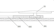
Further, the driving device of the adjusting dial comprises a gear 391, a rack 392, a push rod 393 and a guide sleeve 394 fixedly connected to the bottom center position of the adjusting dial; the rack is meshed with the gear; the outer end of the rack is connected to the inner end of the push rod; the push rod extends outwards to the outer side of the fixed box through a guide sleeve arranged on the surface of the working platform.
Furthermore, the four eccentric shafts are respectively and uniformly distributed in an annular array along the circle center of the adjusting turntable.
Further, one side of the electric push rod is fixedly connected with a laser range finder 5.
Further, the box-type structure is quadrilateral; each clamping plate is parallel to the side of the corresponding box-type structure; two spring telescopic rods are arranged between each clamping plate and the corresponding edge of the box-shaped structure.
The specific embodiment is as follows:
when the eccentric shaft adjusting device is used, the push rod is pushed, slides along the guide sleeve, drives the gear to move inwards, the rack drives the gear to rotate, the gear drives the adjusting turntable to rotate, and the adjusting turntable drives the four eccentric shafts to rotate clockwise; four eccentric shafts push four corresponding adjusting rods to slide clockwise, the four adjusting rods push four adjusting blocks to slide along adjusting holes to enable four clamping plates to be away from each other, a spring telescopic rod is extruded to be compressed and deformed, equipment to be detected is placed on a supporting plate between the four clamping plates, a push rod is loosened to push the four clamping plates to be close to each other under the action of restoring elasticity of the spring telescopic rod, the equipment to be detected is clamped and fixed and is placed in the center of the supporting plate, a detection probe is convenient to position, a second motor is started to drive a second screw rod to rotate, the second screw rod drives a fixing box to slide to a detection frame along a second sliding hole through a second sliding block, the fixing box drives the equipment to move below the detection probe, a first motor is started to drive a first screw rod to rotate, the first screw rod drives a first sliding block to slide left and right along the inner wall of the adjusting box, the first sliding block drives an electric push rod to move left and right through the first sliding hole, realized adjusting to the X axle direction, through the distance of laser range finder detection probe apart from the equipment check point, start electric putter and realized connecting the regulation in Y axle opposite direction, accomplish the location back, start electric putter drive detection probe downstream detect can, can detect equipment automatically, detection efficiency is higher, consuming time is shorter.
Although the present invention has been described with reference to the preferred embodiments, it should be understood that various changes and modifications can be made therein by those skilled in the art without departing from the spirit and scope of the invention as defined by the appended claims.
Claims (7)
1. The utility model provides an electric automation equipment's detection device, includes the workstation, its characterized in that: the left end and the right end of the surface of the workbench are respectively provided with a fixed box and a detection frame;
the detection frame comprises a frame, a detection probe, an electric push rod and a horizontal moving mechanism; the electric push rod can be fixed on the frame in a vertically telescopic manner; the upper end of the detection probe is connected to the output end of the electric push rod and can move along with the up-and-down stretching of the electric push rod; the electric push rod is connected with the horizontal moving mechanism to realize horizontal movement in the front-back direction;
the fixed box comprises a box structure with an opening on the upper surface, a supporting plate, a clamping plate structure, an adjusting block and an adjusting turntable; the bottom surface of the box-type structure is provided with a supporting plate, and the inner cavity of the box-type structure on the upper surface of the supporting plate is internally provided with four clamping plates and four adjusting blocks for driving the corresponding clamping plates to move; when the four clamping plates are loosened, a closed rectangular clamping plate structure can be formed on the surface of the supporting plate; each adjusting block is fixed at the bottom of the corresponding clamping plate to drive the clamping plate to move; a spring telescopic rod is arranged between the outer end of each clamping plate and the side wall of the box-type structure along the moving direction of the clamping plates; the supporting plate is provided with an adjusting hole for the sliding of the adjusting block at the moving position of the adjusting block; the lower part of the supporting plate is provided with an adjusting turntable; four adjusting rods parallel to the surface where the adjusting turnplate is located are arranged on the upper surface of the adjusting turnplate; the bottom of the adjusting block is rotatably connected to the outer end of the adjusting rod, and the inner end of the adjusting rod is hinged to the upper end of the eccentric shaft; the lower end of the eccentric shaft is hinged to the upper surface of the adjusting disc; the rotation direction of the eccentric shaft is the horizontal direction; when the adjusting turntable rotates horizontally, the eccentric shaft is driven to rotate horizontally, and the eccentric shaft rotates horizontally to drive the adjusting rod to move so as to drive the adjusting block to reciprocate along the adjusting hole;
the surface of the workbench is also provided with a fixing box horizontal moving mechanism which can horizontally move the fixing box to the bottom of the detection probe under the detection frame.
2. The detection device of an electrical automation apparatus as set forth in claim 1, wherein: the horizontal moving mechanism comprises an adjusting box arranged at the upper end of the frame and extending along the front-back direction; a hollow first sliding hole is formed in the adjusting box; the first sliding hole is a square through hole extending along the front-back direction; a first screw rod is arranged in the first through hole along the extension direction of the first through hole; the outer surface of the first screw rod is in threaded connection with a first sliding block; the lower surface of the first sliding block is connected with the upper end of the electric push rod; and a driving motor of the first screw rod, namely a first motor, is arranged at one end of the first sliding hole and is connected with the first screw rod.
3. The detection device of an electrical automation apparatus as set forth in claim 1, wherein: the fixed box horizontal moving mechanism comprises a horizontally long-strip moving cavity which is arranged on the upper surface of the workbench and is connected with the left end and the right end; a second screw rod which extends horizontally is arranged in a cavity of the moving cavity; the second sliding block is sleeved on the surface of the second screw rod and can horizontally move in the moving cavity and a second sliding hole at the upper end of the workbench along with the rotation of the second screw rod; the upper surface of the second sliding block is fixedly connected with a fixed box; and a driving motor of the second screw rod, namely a second motor, is arranged at one end of the moving cavity.
4. The detection device of an electrical automation apparatus as set forth in claim 1, wherein: the driving device of the adjusting turntable comprises a gear, a rack, a push rod and a guide sleeve which are fixedly connected to the center of the bottom of the adjusting turntable; the rack is meshed with the gear; the outer end of the rack is connected to the inner end of the push rod; the push rod extends outwards to the outer side of the fixed box through a guide sleeve arranged on the surface of the working platform.
5. The detection device of an electrical automation apparatus as set forth in claim 1, wherein: the four eccentric shafts are respectively and uniformly distributed in an annular array along the circle center of the adjusting turntable.
6. The detection device of an electrical automation apparatus as set forth in claim 1, wherein: and one side of the electric push rod is fixedly connected with the laser range finder.
7. The detection device of an electrical automation apparatus as set forth in claim 1, wherein: the box-type structure is quadrilateral; each clamping plate is parallel to the side of the corresponding box-type structure; two spring telescopic rods are arranged between each clamping plate and the corresponding edge of the box-shaped structure.
Priority Applications (1)
| Application Number | Priority Date | Filing Date | Title |
|---|---|---|---|
| CN202210043373.1A CN114545041A (en) | 2022-01-14 | 2022-01-14 | Detection apparatus for electrical automation equipment |
Applications Claiming Priority (1)
| Application Number | Priority Date | Filing Date | Title |
|---|---|---|---|
| CN202210043373.1A CN114545041A (en) | 2022-01-14 | 2022-01-14 | Detection apparatus for electrical automation equipment |
Publications (1)
| Publication Number | Publication Date |
|---|---|
| CN114545041A true CN114545041A (en) | 2022-05-27 |
Family
ID=81671910
Family Applications (1)
| Application Number | Title | Priority Date | Filing Date |
|---|---|---|---|
| CN202210043373.1A Withdrawn CN114545041A (en) | 2022-01-14 | 2022-01-14 | Detection apparatus for electrical automation equipment |
Country Status (1)
| Country | Link |
|---|---|
| CN (1) | CN114545041A (en) |
Cited By (1)
| Publication number | Priority date | Publication date | Assignee | Title |
|---|---|---|---|---|
| CN115508680A (en) * | 2022-11-09 | 2022-12-23 | 溧阳市明之盛科技有限公司 | Method and device for detecting insulation of pole of automobile power battery |
-
2022
- 2022-01-14 CN CN202210043373.1A patent/CN114545041A/en not_active Withdrawn
Cited By (1)
| Publication number | Priority date | Publication date | Assignee | Title |
|---|---|---|---|---|
| CN115508680A (en) * | 2022-11-09 | 2022-12-23 | 溧阳市明之盛科技有限公司 | Method and device for detecting insulation of pole of automobile power battery |
Similar Documents
| Publication | Publication Date | Title |
|---|---|---|
| CN208299940U (en) | A kind of detection device of double-station camera module | |
| CN114545041A (en) | Detection apparatus for electrical automation equipment | |
| CN216052059U (en) | Automatic tester for digital chips | |
| CN115201029A (en) | Circuit board distortion testing machine with detect structure | |
| CN220040653U (en) | Probe pcba test fixture | |
| CN217941002U (en) | Circuit board electrical performance test analysis device | |
| CN115945401A (en) | Screw torsion check out test set | |
| CN209363056U (en) | A kind of console mode character machining machine | |
| CN209197616U (en) | Inspection tool for automobile instrument panel support | |
| CN114002059A (en) | Automatic chemical engineering clamp for testing performance of flexible circuit board and use method thereof | |
| CN208044010U (en) | Circuit board detecting guide tool | |
| CN112798602A (en) | Bookmark detection device based on industry vision | |
| CN216526117U (en) | Detection device for electric automation equipment | |
| CN214375662U (en) | Production of no frame liquid crystal module panel is with check out test set of being convenient for location | |
| CN220623346U (en) | Motion image measuring distance measuring device | |
| CN220584336U (en) | Circuit board testing machine | |
| CN220019415U (en) | Visual circulation detection device for screw cap | |
| CN216310184U (en) | High-precision test equipment for IGBT power module | |
| CN215180315U (en) | Circuit board flying probe test equipment | |
| CN217272961U (en) | High-precision image full-inspection automatic equipment | |
| CN111496147B (en) | Bending device for probe | |
| CN213600054U (en) | Roughness detection device is used in cell phone stand production | |
| CN219434982U (en) | Chip detection equipment with automatic position adjustment function | |
| CN210374986U (en) | Novel display device measuring instrument for automatic control system | |
| CN215768064U (en) | Bellows fatigue life testing machine for vacuum switch tube |
Legal Events
| Date | Code | Title | Description |
|---|---|---|---|
| PB01 | Publication | ||
| PB01 | Publication | ||
| SE01 | Entry into force of request for substantive examination | ||
| SE01 | Entry into force of request for substantive examination | ||
| WW01 | Invention patent application withdrawn after publication |
Application publication date: 20220527 |
|
| WW01 | Invention patent application withdrawn after publication |