CN114475903A - Transmission mechanism and bicycle without dead points - Google Patents
Transmission mechanism and bicycle without dead points Download PDFInfo
- Publication number
- CN114475903A CN114475903A CN202210171817.XA CN202210171817A CN114475903A CN 114475903 A CN114475903 A CN 114475903A CN 202210171817 A CN202210171817 A CN 202210171817A CN 114475903 A CN114475903 A CN 114475903A
- Authority
- CN
- China
- Prior art keywords
- wheel
- bicycle
- driven wheel
- transmission mechanism
- transmission
- Prior art date
- Legal status (The legal status is an assumption and is not a legal conclusion. Google has not performed a legal analysis and makes no representation as to the accuracy of the status listed.)
- Pending
Links
- 230000005540 biological transmission Effects 0.000 title claims abstract description 104
- 230000007246 mechanism Effects 0.000 title claims abstract description 69
- 238000000034 method Methods 0.000 claims abstract description 16
- 230000001105 regulatory effect Effects 0.000 claims description 16
- 230000001681 protective effect Effects 0.000 claims description 11
- 230000008569 process Effects 0.000 abstract description 11
- 230000007547 defect Effects 0.000 abstract description 7
- 238000009434 installation Methods 0.000 description 11
- 229910000831 Steel Inorganic materials 0.000 description 4
- 238000010791 quenching Methods 0.000 description 4
- 230000000171 quenching effect Effects 0.000 description 4
- 239000010959 steel Substances 0.000 description 4
- 238000005496 tempering Methods 0.000 description 4
- 230000009471 action Effects 0.000 description 2
- 239000000428 dust Substances 0.000 description 2
- 230000035790 physiological processes and functions Effects 0.000 description 2
- 239000006096 absorbing agent Substances 0.000 description 1
- 230000009286 beneficial effect Effects 0.000 description 1
- 230000008859 change Effects 0.000 description 1
- 230000000694 effects Effects 0.000 description 1
- 238000004519 manufacturing process Methods 0.000 description 1
- 230000004048 modification Effects 0.000 description 1
- 238000012986 modification Methods 0.000 description 1
- 230000035939 shock Effects 0.000 description 1
Images


Classifications
-
- B—PERFORMING OPERATIONS; TRANSPORTING
- B62—LAND VEHICLES FOR TRAVELLING OTHERWISE THAN ON RAILS
- B62M—RIDER PROPULSION OF WHEELED VEHICLES OR SLEDGES; POWERED PROPULSION OF SLEDGES OR SINGLE-TRACK CYCLES; TRANSMISSIONS SPECIALLY ADAPTED FOR SUCH VEHICLES
- B62M23/00—Transmissions characterised by use of other elements; Other transmissions
-
- B—PERFORMING OPERATIONS; TRANSPORTING
- B62—LAND VEHICLES FOR TRAVELLING OTHERWISE THAN ON RAILS
- B62M—RIDER PROPULSION OF WHEELED VEHICLES OR SLEDGES; POWERED PROPULSION OF SLEDGES OR SINGLE-TRACK CYCLES; TRANSMISSIONS SPECIALLY ADAPTED FOR SUCH VEHICLES
- B62M11/00—Transmissions characterised by the use of interengaging toothed wheels or frictionally-engaging wheels
- B62M11/04—Transmissions characterised by the use of interengaging toothed wheels or frictionally-engaging wheels of changeable ratio
- B62M11/06—Transmissions characterised by the use of interengaging toothed wheels or frictionally-engaging wheels of changeable ratio with spur gear wheels
-
- B—PERFORMING OPERATIONS; TRANSPORTING
- B62—LAND VEHICLES FOR TRAVELLING OTHERWISE THAN ON RAILS
- B62M—RIDER PROPULSION OF WHEELED VEHICLES OR SLEDGES; POWERED PROPULSION OF SLEDGES OR SINGLE-TRACK CYCLES; TRANSMISSIONS SPECIALLY ADAPTED FOR SUCH VEHICLES
- B62M15/00—Transmissions characterised by use of crank shafts and coupling rods
Landscapes
- Engineering & Computer Science (AREA)
- Chemical & Material Sciences (AREA)
- Combustion & Propulsion (AREA)
- Transportation (AREA)
- Mechanical Engineering (AREA)
- Automatic Cycles, And Cycles In General (AREA)
Abstract
The invention discloses a transmission mechanism and a dead-point-free bicycle, and belongs to the technical field of vehicles. The transmission mechanism includes: a drive wheel for inputting power; the driven wheel is arranged beside the driving wheel, is positioned at the same height position with the driving wheel and is used for outputting power; the connecting rod is in transmission connection with the driving wheel and the driven wheel respectively; three mounting positions I are uniformly distributed at the edge of the end face of the driving wheel; three mounting positions II are uniformly distributed at positions corresponding to the edge of the end face of the driven wheel; the number of the connecting rods is three, two ends of each connecting rod are respectively and rotatably connected with the corresponding first mounting position and the second mounting position, and the three connecting rods are parallel to each other. According to the dead-point-free bicycle, by applying the transmission mechanism disclosed by the invention, when the bicycle is ridden, the pedal crank and the pedal input power, a dead point position cannot occur in the process, the riding experience is improved, the power input is optimized, the bicycle is easier to ride, and the defects that a chain is not required to be used, the chain is not dropped and the like cannot occur.
Description
Technical Field
The invention belongs to the technical field of vehicles, and particularly relates to a transmission mechanism and a dead-point-free bicycle.
Background
The transmission part of the traditional bicycle consists of pedals, a crank, a chain wheel, a middle shaft, a chain and a flywheel, wherein a large chain disc is arranged at the middle shaft of the pedals, the flywheel is arranged at the rear shaft, the chain is arranged on the two chain discs, the pedals are treaded by two feet of a rider during the motion process of the bicycle to drive the crank to do rotary motion, and power is transmitted to the flywheel on the rear shaft through the chain wheel to drive wheels to rotate to go forward.
The magnitude and direction of the acting force of the soles on the pedals are changed along with the position of the cranks in the process of driving the cranks to rotate, each crank passes through the position vertical to the ground 2 times in the process of one cycle of the cranks, the position is equivalent to a 'dead point' of a mechanism, and a rider generally applies extra acting force to bypass the 'dead point' by means of inertia or a side body in the process of rotating the cranks in order to smoothly pass through the position, and particularly when the rider drives on a rugged road or climbs a slope, the rider often feels more labored.
Through retrieval, the Chinese patent publication number: CN 106428405A; the publication date is as follows: 22 months 2 in 2017; disclosed is a dead-point-free driving bottom bracket for a bicycle, comprising: a drive arrangement and a driven arrangement, the drive arrangement comprising: first crank, rotation install first footboard, the second crank that first crank rotation was held and rotation install the second footboard of second crank rotation end, its characterized in that, drive arrangement still includes: the first middle shaft is fixedly connected to the fixed end of the first crank, the second middle shaft is fixedly connected to the fixed end of the second crank, a first gear is fixedly connected to one end, far away from the first crank, of the first middle shaft, a second gear is fixedly connected to one end, far away from the second crank, of the second middle shaft, an intermediate shaft, a first driven gear fixed to one end of the intermediate shaft and meshed with the first gear, and a second driven gear fixed to the other end of the intermediate shaft and meshed with the second gear; the driven device comprises a chain wheel fixedly arranged on the first middle shaft or the second middle shaft; or the driven device comprises bevel teeth fixedly arranged at one end of the intermediate shaft; the included angle between the first crank and the second crank is changed, and when any one of the first crank and the second crank rotates to be vertical to the ground, the other crank is not vertical to the ground. This application improves through the drive disk assembly to the bicycle for first crank and second crank contained angle at the operation in-process change, can not appear exerting oneself the dead point position simultaneously, and then overcome the dead point defect, but the structural design of this application needs to carry out great institutional advancement in bicycle crank pedal position department, need occupy great space on the one hand, and the defect that the chain dropped is difficult to solve to this structure of on the other hand.
In addition, for example, chinese patent publication no: CN 211001695U; the publication date is as follows: 14 days 7 month 2020; the utility model discloses a bicycle does not have dead point pedal device, including the driven pole that controls the phase difference and be 180 degrees, the running-board, the frame still includes two rearmounted axles, two intermediate levers, two main driving poles, the direction of intermediate lever and main driving pole is unanimous, the inner fixed connection of intermediate lever and axle, main driving pole and the outer end fixed connection of axle, rearmounted axle and frame swivelling joint, be equipped with the track groove on the intermediate lever, be equipped with the gyro wheel on the driven pole, the gyro wheel rolls along the track groove, main driving pole and running-board swivelling joint. The structure of this application, the running-board of its one side is when being stepped on to the lowest position, and the main drive pole of opposite side slopes forward an angle to make and trample no dead point, though overcome the dead point defect, in the actual in-process of riding, it is not good to ride that driving foot portion is exerted oneself power and the pedal is experienced, is difficult to popularize and apply.
Disclosure of Invention
In order to solve at least one of the above-mentioned technical problems, according to an aspect of the present invention, there is provided a transmission mechanism including,
a drive wheel for inputting power;
the driven wheel is arranged beside the driving wheel, is positioned at the same height position with the driving wheel and is used for outputting power;
the connecting rod is in transmission connection with the driving wheel and the driven wheel respectively;
three mounting positions I are uniformly distributed at the edge of the end face of the driving wheel;
three mounting positions II are uniformly distributed at positions corresponding to the edge of the end face of the driven wheel;
the number of the connecting rods is three, two ends of each connecting rod are respectively and rotatably connected with the corresponding first mounting position and the second mounting position, and the three connecting rods are parallel to each other.
According to the transmission mechanism of the embodiment of the invention, optionally, the driving wheel and the driven wheel are arranged on different sides of the connecting rod.
According to an aspect of the present invention, there is provided a dead-center-free bicycle including:
the transmission mechanism is the transmission mechanism of the invention;
the transmission mechanism is arranged at the rear lower fork and the lower pipe of the frame main body;
a front wheel mounted below the front end of the frame body;
the rear wheel is arranged below the rear end of the frame main body, and a driven wheel of the transmission mechanism is in transmission connection with the rear wheel;
and the crank pedal is in transmission connection with a driving wheel of the transmission mechanism and is used for inputting power.
According to the dead-center-free bicycle provided by the embodiment of the invention, optionally, two transmission mechanisms are arranged on two sides of the frame main body respectively.
According to the bicycle without the dead point, optionally, a transmission position is axially arranged at the axis of the driving wheel of the transmission mechanism, and the crank pedal inputs power to the driving wheel through the transmission position.
According to the dead-center-free bicycle provided by the embodiment of the invention, optionally, the driven wheel of the transmission mechanism is a gear.
The dead-point-free bicycle according to the embodiment of the invention optionally further comprises a speed regulating mechanism, which is in transmission connection with the driven wheel and the rear wheel and is used for regulating the transmission ratio of the driven wheel and the rear wheel.
According to the bicycle without dead point in the embodiment of the present invention, optionally, the speed adjusting mechanism includes:
the idle wheel is arranged on the rear lower fork and meshed with the driven wheel;
the axle center of the pinion is in transmission connection with the axle center of the rear wheel, and the pinion is meshed with the idler wheel.
According to the dead-center-free bicycle of the embodiment of the present invention, optionally,
the pinion is arranged between the driven wheel and the rear lower fork;
the idler thickness is greater than the sum of the driven wheel and the pinion thickness.
According to the bicycle without dead point of the embodiment of the invention, optionally, the bicycle further comprises:
and the protective shell is covered on the outer sides of the driven wheel and the speed regulating mechanism and is fixedly connected with the frame main body.
Advantageous effects
Compared with the prior art, the invention at least has the following beneficial effects:
(1) the transmission mechanism can effectively overcome the dead point position in the rotation process of the driving wheel, effectively utilizes the force application of the human body, exerts the maximum physiological function of the human body, replaces chain transmission, avoids the occurrence of chain dropping phenomenon, and is more suitable for being applied to the field of bicycle transmission;
(2) according to the dead-point-free bicycle, when the bicycle is ridden, the pedal crank and the pedal input power, no dead point position occurs in the process, the riding experience is improved, the power input is optimized, the bicycle is ridden more easily, and the dead-point-free bicycle does not need a chain, and cannot have the defects of chain falling and the like;
(3) according to the dead-point-free bicycle, the two transmission mechanisms are respectively arranged on the left side and the right side of the frame main body and are matched with the two crank pedals to input power simultaneously, so that the design of riding actions of a human body is more met, and the power input is also improved;
(4) the dead-point-free bicycle is provided with the speed regulating mechanism, so that the driving wheel and the rear wheel can be conveniently controlled to have a proper transmission ratio according to the riding requirement, and the riding is convenient;
(5) the dead-point-free bicycle adopts the speed regulating mechanism consisting of the idle wheel and the pinion, has simple structure and small occupied installation space, and is convenient for bicycle manufacture and installation design of other parts;
(6) the dead-point-free bicycle is provided with the protective shell, has a protective effect on parts of a gear structure, prevents dust and sundries, and avoids influencing gear transmission.
Drawings
In order to more clearly illustrate the technical solutions of the embodiments of the present invention, the drawings of the embodiments will be briefly described below, and it is apparent that the drawings in the following description only relate to some embodiments of the present invention and are not limiting on the present invention.
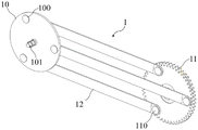
FIG. 1 shows a schematic of the transmission of the present invention;
FIG. 2 shows a schematic view of another perspective of the transmission of the present invention;
FIG. 3 shows a schematic view of the dead-center-free bicycle of the present invention;
FIG. 4 is a schematic view of the position of the transmission mechanism in the dead-center-free bicycle of the present invention;
FIG. 5 is a schematic view of another perspective of the position of the transmission mechanism in the bicycle without dead center according to the present invention;
FIG. 6 illustrates a half cross-sectional view of the dead-center-free bicycle of the present invention;
FIG. 7 shows an enlarged view at A in FIG. 6;
FIG. 8 is a schematic view of a dead-center-free bicycle of embodiment 9;
reference numerals:
1. a transmission mechanism; 10. a driving wheel; 100. a first mounting position; 101. a transmission position; 11. a driven wheel; 110. a second mounting position; 111. installing a shaft; 12. a connecting rod;
2. a frame main body; 20. a rear upper fork; 21. a rear lower fork; 22. a lower pipe; 23. a U-shaped frame; 24. a mounting frame;
3. a front wheel;
4. a rear wheel;
5. crank pedal;
6. a speed regulating mechanism; 60. an idler pulley; 61. a pinion gear;
7. and (4) a protective shell.
Detailed Description
In order to make the objects, technical solutions and advantages of the embodiments of the present invention clearer, the technical solutions of the embodiments of the present invention will be clearly and completely described below with reference to the drawings of the embodiments of the present invention. It is to be understood that the embodiments described are only a few embodiments of the present invention, and not all embodiments.
Unless defined otherwise, technical or scientific terms used herein shall have the ordinary meaning as understood by one of ordinary skill in the art to which this invention belongs. The use of "first," "second," and similar terms in the description and in the claims of the present application does not denote any order, quantity, or importance, but rather the terms are used to distinguish one element from another. Also, the use of the terms "a" or "an" and the like do not denote a limitation of quantity, but rather denote the presence of at least one.
The invention provides a transmission mechanism and a dead-point-free bicycle, aiming at the defects that the prior bicycle has a dead point position of exerting force in the riding process, a rider needs to exert extra acting force to bypass the dead point position, particularly, the rider can feel more labored to ride when the bicycle runs on a rugged road or climbs, and the chain is easy to shake in the process so as to drop.
Example 1
The transmission mechanism of the embodiment comprises a transmission mechanism,
a drive wheel 10 for inputting power;
a driven wheel 11 disposed beside the driving wheel 10 at the same height position as the driving wheel 10 for outputting power;
the connecting rod 12 is respectively in transmission connection with the driving wheel 10 and the driven wheel 11;
the method is characterized in that:
three mounting positions I100 are uniformly distributed at the edge of the end face of the driving wheel 10;
the corresponding positions of the edge of the end face of the driven wheel 11 are uniformly provided with a second three mounting positions 110;
the number of the connecting rods 12 is three, two ends of each connecting rod 12 are respectively and rotatably connected with the corresponding first mounting position 100 and the second mounting position 110, and the three connecting rods 12 are parallel to each other.
As shown in fig. 1 and fig. 2, in the transmission mechanism of the present embodiment, three first installation positions 100 are uniformly distributed at the edge of the end surface of the driving wheel 10, the central angles of the first two adjacent installation positions 100 are both 120 °, similarly, three second installation positions 110 are also uniformly distributed at the edge of the end surface of the driven wheel 11, the central angles of the second two adjacent installation positions 110 are also both 120 °, the height positions of the driving wheel 10 and the driven wheel 11 are the same, and the initial height positions of the first installation positions 100 and the second installation positions 110 are in one-to-one correspondence, two ends of the connecting rods 12 are rotatably connected with the driving wheel 10 and the driven wheel 11 through corresponding installation positions, for example, the ends are rotatably connected with the corresponding installation positions through rotating shafts, after the three connecting rods 12 are connected with the corresponding installation positions, the three connecting rods 12 are in a horizontal state, further, assuming that the end surfaces of the driving wheel 10 and the driven wheel 11 are both vertically arranged, and after the three connecting rods 12 are installed and connected, they are in different vertical surface positions, when the driving wheel 10 and the driven wheel 11 rotate, the three connecting rods 12 do not interfere with each other.
The embodiment utilizes the transmission mechanism with three connecting rods, can effectively overcome the dead point position in the rotating process of the driving wheel 10, effectively utilizes the force applied by the human body, exerts the maximum physiological function of the human body, replaces chain transmission, avoids the phenomenon of chain dropping, and is more suitable for being applied to the field of bicycle transmission.
Example 2
The transmission mechanism of the present embodiment is further improved on the basis of embodiment 1, and the driving wheel 10 and the driven wheel 11 are disposed on different sides of the connecting rod 12.
As shown in fig. 1 and 2, in the present embodiment, one end of the connecting rod 12 is rotatably connected to the right end face of the driving wheel 10, and the other end of the connecting rod 12 is rotatably connected to the left end face of the driven wheel 11, so that the power input structure and the power output structure at the driving wheel 10 and the driven wheel 11 can be further conveniently arranged, interference between the structures and the connecting rod 12 is avoided, and normal transmission operation is ensured.
Example 3
The no dead point bicycle of this embodiment includes:
a transmission mechanism 1 which is the transmission mechanism of embodiment 2;
the transmission mechanism 1 is arranged at a rear lower fork 21 and a lower pipe 22 of the frame main body 2;
a front wheel 3 mounted below the front end of the frame body 2;
the rear wheel 4 is arranged below the rear end of the frame main body 2, and a driven wheel 11 of the transmission mechanism 1 is in transmission connection with the rear wheel 4;
and the crank pedal 5 is in transmission connection with a driving wheel 10 of the transmission mechanism 1 and is used for inputting power.
As shown in fig. 3, the frame body 2 includes the necessary structures of a conventional bicycle body, such as a front portion, a seat and a frame, the front portion includes a handlebar, a head tube, a shock absorber, a front brake, a front fork, etc., the seat includes a cushion, a seat pillar, etc., the frame includes an upper tube, a lower tube 22, a vertical tube, a rear upper fork 20 and a rear lower fork 21, and the frame body 2 is a common structure of a conventional bicycle and is not repeated herein.
In this embodiment, the transmission mechanism 1 is installed at the positions of the rear bottom fork 21 and the lower tube 22 of the frame main body 2, that is, the driving wheel 10 is fixed at the position of the lower tube 22, and the driven wheel 11 is fixed at the position of the rear bottom fork 21, further, the front wheels 3 are installed below the front end of the frame main body 2 and at the positions of the front forks, the rear wheel 4 is installed below the rear end of the frame main body 2, that is, at the position of the rear bottom fork 21, the driven wheel 11 of the transmission mechanism 1 is in transmission connection with the rear wheel 4 for outputting the power, and the crank pedals 5 are in transmission connection with the driving wheel 10 of the transmission mechanism 1 for inputting the power, thereby forming the bicycle structure of this embodiment.
The dead-point-free bicycle of the embodiment utilizes the transmission mechanism of the invention, when the bicycle is ridden, the pedal crank and pedal 5 inputs power, no dead point position occurs in the process, the riding experience is improved, the power input is optimized, the bicycle is ridden more easily, and the dead-point-free bicycle of the embodiment does not need to use a chain, and the defects of chain falling and the like do not occur.
Example 4
The dead-point-free bicycle of the embodiment is further improved on the basis of the embodiment 3, and the two transmission mechanisms 1 are respectively arranged on two sides of the frame main body 2.
As shown in fig. 3, two transmission mechanisms 1 are respectively arranged at the left side and the right side of the frame main body 2, and are matched with two crank pedals 5 to simultaneously input power, so that the bicycle is more suitable for the design of human body riding action, and the power input is also improved.
Further, in this embodiment, the driving wheels 10 of the two transmission mechanisms 1 are fixed to the lower tube 22 through the U-shaped frame 23, specifically, the two driving wheels 10 are symmetrically arranged at two sides of the bottom end of the lower tube 22, the axes of the two driving wheels are collinear, an axis body is formed at the outer side of the axis of each driving wheel 10 along the axial direction, the axis body protrudes from the end surface of the driving wheel 10, which is not connected with the connecting rod 12, the middle of the U-shaped frame 23 is welded and fixed to the bottom end of the lower tube 22, and two ends of the U-shaped frame 23 are respectively sleeved at two ends of the axis body, so as to fix the two driving wheels 10.
Example 5
The dead-point-free bicycle of the embodiment is further improved on the basis of the embodiment 4, a transmission position 101 is axially arranged at the axis of a driving wheel 10 of the transmission mechanism 1, and the crank pedals 5 input power to the driving wheel 10 through the transmission position 101.
As shown in fig. 4, in this embodiment, the position of the driving wheel 10 where power is input is the axis, and the crank pedals 5 are in transmission connection with the transmission position 101 at the axis of the driving wheel 10, so as to input power to the driving wheel 10 through the pedal to rotate the driving wheel.
More specifically, in this embodiment, the transmission position 101 is a shaft body passing through the axis of the driving wheel 10, and one end of the shaft body is fixedly connected with the axis of the driving wheel 10 through a key, and the other end is also fixedly connected with the crank pedal 5 through a key.
Example 6
The dead-point-free bicycle of the embodiment is further improved on the basis of the embodiment 5, and the driven wheel 11 of the transmission mechanism 1 is a gear;
the speed regulating device also comprises a speed regulating mechanism 6 which is in transmission connection with the driven wheel 11 and the rear wheel 4 and is used for regulating the transmission ratio of the driven wheel 11 and the rear wheel 4.
The driven wheel 11 of the present embodiment is a gear, and outputs power to the rear wheel 4 through gear transmission.
Further, because the transmission mechanism 1 adopted in the embodiment has the transmission ratio of 1: 1 between the driving wheel 10 and the driven wheel 11, when the transmission mechanism 1 of the embodiment is directly used for replacing a chain transmission mechanism, a person only needs to run a circle of the bicycle when pedaling the bicycle for one circle, which is relatively labor-consuming, so that the transmission ratio needs to be increased, and therefore, the speed regulating mechanism 6 is designed, and further, the proper transmission ratio between the driven wheel 11 and the rear wheel 4 can be conveniently controlled according to the riding requirement, and the riding is convenient.
Example 7
The dead-point-free bicycle of the embodiment is further improved on the basis of the embodiment 6, and the speed regulating mechanism 6 comprises:
an idle gear 60 mounted on the rear lower fork 21, the idle gear 60 meshing with the driven gear 11;
and the axis of the pinion 61 is in transmission connection with the axis of the rear wheel 4, and the pinion 61 is meshed with the idle wheel 60.
As shown in fig. 4 and 5, the idle gear 60 cooperates with the pinion 61 to form the speed adjusting mechanism 6 of the present embodiment, wherein the gear ratio of the driven wheel 11 and the pinion 61 is a transmission ratio, and the idle gear 60 is designed to adjust the rotation direction, so that the final rotation direction is opposite by only the engagement transmission of the pinion 61 and the driven wheel 11, i.e. the human foot is pedaled forward but the bicycle is driven backward, and therefore, the direction of rotation needs to be changed by the idle gear 60.
Example 8
The dead-center-free bicycle of the present embodiment is further improved over embodiment 7 in that the pinion 61 is disposed between the driven wheel 11 and the rear lower fork 21;
the idler 60 has a thickness greater than the sum of the thicknesses of the driven wheel 11 and the pinion 61.
As shown in fig. 6 and 7, in the present embodiment, the pinion 61 is located between the driven wheel 11 and the rear bottom fork 21, the axle center of the pinion 11 is in transmission connection with the axle center of the rear wheel 4 through the axle body, and the idle wheel 60 is disposed behind the driven wheel 11 and is engaged with the driven wheel 11 and the pinion 61 at the same time.
Example 9
The dead-point-free bicycle of the embodiment is further improved on the basis of the embodiment 8, and further comprises:
and the protective shell 7 is covered on the outer sides of the driven wheel 11 and the speed regulating mechanism 6, and the protective shell 7 is fixedly connected with the frame main body 2.
As shown in fig. 7 and 8, in the embodiment, the mounting frame 24 is vertically welded at the tail end of the rear lower fork 21, the protective shell 7 covers the outer side of each gear structure and is fixed with the mounting frame 24, and the protective shell can be welded and fixed or can be detachably fixed, so that the protective shell plays a role in protecting the gear structures, prevents dust and sundries, and avoids influencing gear transmission.
Example 10
The embodiment shows a specific parameter design of a dead-center-free bicycle.
In the embodiment, the transmission ratio i of the driven wheel 11 to the rear wheel 4 is designed to be 2.5, the modulus m is selected to be 3 according to a standard modulus series list specified in China, the driven wheel 11, the idle wheel 60 and the pinion 61 are subjected to quenching and tempering treatment by 45 steel in consideration of low power of a bicycle, the hardness of tooth surfaces of the driven wheel 11, the idle wheel 60 and the pinion 61 are 220HBS, 260HBS and 260HBS in sequence, the soft tooth surface closed type transmission is adopted, the load is stable, 7-level precision is primarily selected, and the tooth number Z of the pinion 61 is designed120, idler gear 60 teeth count Z 220, large gear tooth number Z3=i*Z2=2.5×20=50。
Further, regarding the structural dimensions of the driven wheel 11:
reference circle diameter d1=3×50=150mm;
Tooth crest height ha1=ha *m=1×3=3mm(ha *=1);
Height of tooth root
Full height h of teeth1=ha1+hf1=3+3.75=6.75mm;
Diameter d of addendum circlea1=d1+2ha1=150+2×3=156mm;
Root diameter df1=d1-2hf1=150-2×3.75=142.5mm;
Pressure angle alpha1=20°;
Width of tooth b1=10mm。
For the structural dimensions of the idler 60:
reference circle diameter d2=3×20=60mm;
Tooth crest height ha2=ha *m=1×3=3mm(ha *=1);
Height of tooth root
Full height h of teeth2=ha2+hf2=3+3.75=6.75mm;
Diameter d of addendum circlea2=d2+2ha2=60+2×3=66mm;
Root diameter df2=d2-2hf2=60-2×3.75=52.5mm;
Pressure angle alpha2=20°;
Width of tooth b2=5mm。
For the structural dimensions of the pinion 61:
reference circle diameter d3=3×20=60mm;
Tooth crest height ha3=ha *m=1×3=3mm(ha *=1);
Height of tooth root
Full height h of teeth3=ha3+hf3=3+3.75=6.75mm;
Diameter d of addendum circlea3=d3+2ha3=60+2×3=66mm;
Root diameter df3=d-2hf3=60-2×3.75=52.5mm;
Pressure angle alpha3=20°;
Width of tooth b3=5mm。
For the structural size of the driving wheel 10:
diameter d4=150mm;
Disc thickness b4=5mm。
The rod thickness of the connecting rod 12 is 3 mm.
Further, the wheel shaft at the driven wheel 11 is subjected to quenching and tempering by 45 steel, a deep groove ball bearing is adopted, one end of a shaft system is fixed in a one-way mode by adopting a flange type bearing cover, the right end of the bearing is positioned and fixed by a shaft shoulder, the left end of the bearing is fixed with a shaft end retainer ring by a countersunk head screw, and the tail end of the shaft is screwed into the rear lower fork 21 by threads; more specifically, a deep groove ball bearing with the inner diameter of 10mm, the outer diameter of 26mm and the width of 5mm is selected, the height of a positioning shaft shoulder is 2mm, the tail end of a shaft is screwed into the rear lower fork 21, a tool withdrawal groove is reserved, the diameter of the shaft at the tool withdrawal groove is 12mm, the head end of the shaft is fixed by a countersunk screw and a shaft end check ring, and the countersunk screw of M3 is selected; the length of the shaft section matched with the bearing is equal to the width of the bearing, so the shaft section is 5mm, the whole shaft length is determined by the widths of the rear lower fork 21, the pinion 61 and the idle wheel 60, the whole shaft length is 32mm, the length of the thread at the tail end of the shaft is determined by the thickness of the rear lower fork 21, the length of the thread section is 12mm, and the shaft length of the middle section is 13 mm.
Further, the wheel shaft at the position of the idle wheel 60 is subjected to quenching and tempering by 45 steel, deep groove ball bearings of the same type as the driven wheel 11 are adopted, the thickness of the idle wheel is 20mm, two deep groove ball bearings are required to be added, the bearings are fixed by a shaft sleeve, a flange type bearing cover is adopted to realize one-way fixation of one end of a shaft system, the right end of one bearing is fixed by a shaft shoulder, the left end of the other bearing is fixed by a countersunk head screw and a shaft end retainer ring, and the tail end of the shaft is screwed into the rear lower fork 21 by threads; more specifically, the size of the bearing is the same as the size of the bearing employed for the driven wheel 11; the axial dimension of the wheel axle at the position of the idle wheel 60 is 5mm, the length of the shaft sleeve is 15mm, the whole shaft length is determined by the widths of the rear lower fork 21 and the driven wheel 11, the whole shaft length is 32mm, the length of the thread at the tail end of the shaft is determined by the thickness of the rear lower fork 21, the length of the thread at the tail end of the shaft is 11mm, and the shaft length of the middle section is 4 mm.
Further, a wheel shaft at the position of a pinion 61 is subjected to quenching and tempering by 45 steel, the shaft at the position of the pinion 61 is a shaft at the position of a rear wheel 4, the left end and the right end are symmetrical, the left end and the right end are respectively connected with the pinion 61 by an A-type common flat key to rotate, two ends of the shaft are positioned by a countersunk screw and a shaft end check ring, a bearing is required to be arranged at the connection position of the shaft and the rear lower fork 21, a deep groove ball bearing with the same model is selected in the same way, the position between the pinion 61 and the bearing is positioned by a shaft sleeve, and the other end of the bearing is positioned by a shaft shoulder; more specifically, the size of the bearing is the same as the size of the bearing employed for the driven wheel 11; selecting an M3 countersunk head screw at the diameter of the shaft end, and checking that the size of a flat key is 3 multiplied by 3 and the length of the key is 8 mm; the length of the shaft section matched with the bearing is equal to the sum of the width of the pinion 51, the length of the shaft sleeve and the width of the bearing, the length of the shaft sleeve is 7mm, the lengths of the shaft sections at the left end and the right end are 17mm, the whole shaft length is determined by the width of the rear wheel 4, the tire width of the rear wheel 4 is 40mm, the whole shaft length is 97mm, and the shaft length of the middle section is 63 mm.
The rest structural dimensions of the bicycle refer to the structural dimensions of the conventional bicycle, and no special design is provided.
The dead point-free bicycle of this embodiment rides and experiences the in-process, compares in traditional chain bicycle, and is more laborsaving, and the fault rate is lower.
The examples described herein are merely illustrative of the preferred embodiments of the present invention and do not limit the spirit and scope of the present invention, and various modifications and improvements made to the technical solutions of the present invention by those skilled in the art without departing from the design concept of the present invention shall fall within the protection scope of the present invention.
Claims (10)
1. A transmission mechanism comprises a transmission mechanism body and a transmission mechanism body,
a drive wheel (10) for inputting power;
a driven wheel (11) which is arranged beside the driving wheel (10), is positioned at the same height position with the driving wheel (10) and is used for outputting power;
the connecting rod (12) is respectively in transmission connection with the driving wheel (10) and the driven wheel (11);
the method is characterized in that:
three mounting positions I (100) are uniformly distributed at the edge of the end face of the driving wheel (10);
three mounting positions II (110) are uniformly distributed at positions corresponding to the edge of the end face of the driven wheel (11);
the number of the connecting rods (12) is three, two ends of each connecting rod (12) are respectively rotatably connected with the corresponding mounting position I (100) and the mounting position II (110), and the three connecting rods (12) are parallel to each other.
2. A transmission mechanism as claimed in claim 1, wherein: the driving wheel (10) and the driven wheel (11) are arranged on two different sides of the connecting rod (12).
3. A dead-center-free bicycle, comprising:
a transmission mechanism (1) according to any one of claims 1 to 2;
the transmission mechanism (1) is arranged at a rear lower fork (21) and a lower pipe (22) of the frame main body (2);
a front wheel (3) mounted below the front end of the frame body (2);
the rear wheel (4) is arranged below the rear end of the frame main body (2), and a driven wheel (11) of the transmission mechanism (1) is in transmission connection with the rear wheel (4);
the crank pedal (5) is in transmission connection with a driving wheel (10) of the transmission mechanism (1) and is used for inputting power.
4. A dead-center-free bicycle according to claim 3, wherein: the two transmission mechanisms (1) are respectively arranged on two sides of the frame main body (2).
5. The bicycle of claim 4, wherein: the crank pedal (5) inputs power to the driving wheel (10) through the transmission position (101).
6. The bicycle of claim 5, wherein: the driven wheel (11) of the transmission mechanism (1) is a gear.
7. The bicycle of claim 6, wherein: the speed regulating device also comprises a speed regulating mechanism (6) which is in transmission connection with the driven wheel (11) and the rear wheel (4) and is used for regulating the transmission ratio of the driven wheel (11) and the rear wheel (4).
8. A bicycle without dead spots according to claim 7, characterised in that the governor mechanism (6) comprises:
an idle wheel (60) mounted on the rear lower fork (21), the idle wheel (60) meshing with the driven wheel (11);
and the axis of the pinion (61) is in transmission connection with the axis of the rear wheel (4), and the pinion (61) is meshed with the idle wheel (60).
9. The dead-center-free bicycle according to claim 8, wherein:
the pinion (61) is arranged between the driven wheel (11) and the rear lower fork (21);
the thickness of the idle wheel (60) is larger than the sum of the thicknesses of the driven wheel (11) and the pinion (61).
10. The bicycle of claim 9, further comprising:
and the protective shell (7) is covered on the outer sides of the driven wheel (11) and the speed regulating mechanism (6), and the protective shell (7) is fixedly connected with the frame main body (2).
Priority Applications (1)
| Application Number | Priority Date | Filing Date | Title |
|---|---|---|---|
| CN202210171817.XA CN114475903A (en) | 2022-02-24 | 2022-02-24 | Transmission mechanism and bicycle without dead points |
Applications Claiming Priority (1)
| Application Number | Priority Date | Filing Date | Title |
|---|---|---|---|
| CN202210171817.XA CN114475903A (en) | 2022-02-24 | 2022-02-24 | Transmission mechanism and bicycle without dead points |
Publications (1)
| Publication Number | Publication Date |
|---|---|
| CN114475903A true CN114475903A (en) | 2022-05-13 |
Family
ID=81483620
Family Applications (1)
| Application Number | Title | Priority Date | Filing Date |
|---|---|---|---|
| CN202210171817.XA Pending CN114475903A (en) | 2022-02-24 | 2022-02-24 | Transmission mechanism and bicycle without dead points |
Country Status (1)
| Country | Link |
|---|---|
| CN (1) | CN114475903A (en) |
Citations (9)
| Publication number | Priority date | Publication date | Assignee | Title |
|---|---|---|---|---|
| GB314102A (en) * | 1928-02-20 | 1929-06-20 | Walter Gordon Wilson | An improved driving transmission for oil driven locomotives |
| GB372486A (en) * | 1931-03-19 | 1932-05-12 | Luigi Febbraro | Improvements in power-transmission linkages |
| CN201619661U (en) * | 2009-12-04 | 2010-11-03 | 黄鑑淼 | Speed-increase transmission device of bicycle |
| CN203601519U (en) * | 2013-12-13 | 2014-05-21 | 李辉 | Bicycle driven by crank rocker |
| CN106428405A (en) * | 2016-10-13 | 2017-02-22 | 李晓成 | Bicycle driving middle shaft with no dead point |
| CN107128435A (en) * | 2017-05-05 | 2017-09-05 | 河海大学常州校区 | Rear wheel drive part, back wheel driving gear and application its without chain bicycle with pedal |
| CN111003101A (en) * | 2019-12-26 | 2020-04-14 | 温州职业技术学院 | Novel transmission device of bicycle |
| CN211001695U (en) * | 2019-09-12 | 2020-07-14 | 王相军 | Dead-point-free pedal device of bicycle |
| CN211766098U (en) * | 2020-03-31 | 2020-10-27 | 晏勇 | High-speed labor-saving bicycle |
-
2022
- 2022-02-24 CN CN202210171817.XA patent/CN114475903A/en active Pending
Patent Citations (9)
| Publication number | Priority date | Publication date | Assignee | Title |
|---|---|---|---|---|
| GB314102A (en) * | 1928-02-20 | 1929-06-20 | Walter Gordon Wilson | An improved driving transmission for oil driven locomotives |
| GB372486A (en) * | 1931-03-19 | 1932-05-12 | Luigi Febbraro | Improvements in power-transmission linkages |
| CN201619661U (en) * | 2009-12-04 | 2010-11-03 | 黄鑑淼 | Speed-increase transmission device of bicycle |
| CN203601519U (en) * | 2013-12-13 | 2014-05-21 | 李辉 | Bicycle driven by crank rocker |
| CN106428405A (en) * | 2016-10-13 | 2017-02-22 | 李晓成 | Bicycle driving middle shaft with no dead point |
| CN107128435A (en) * | 2017-05-05 | 2017-09-05 | 河海大学常州校区 | Rear wheel drive part, back wheel driving gear and application its without chain bicycle with pedal |
| CN211001695U (en) * | 2019-09-12 | 2020-07-14 | 王相军 | Dead-point-free pedal device of bicycle |
| CN111003101A (en) * | 2019-12-26 | 2020-04-14 | 温州职业技术学院 | Novel transmission device of bicycle |
| CN211766098U (en) * | 2020-03-31 | 2020-10-27 | 晏勇 | High-speed labor-saving bicycle |
Non-Patent Citations (1)
| Title |
|---|
| 卜云峰;王文志;侯志伟;左晓明;: "自行车驱动机构的创新设计与分析", 机床与液压, no. 02 * |
Similar Documents
| Publication | Publication Date | Title |
|---|---|---|
| US6182991B1 (en) | Two wheel drive bicycle with a shock-absorbing front fork | |
| EP0895503B1 (en) | Two-wheel drive bicycle | |
| US5577749A (en) | Twin gear drive assembly for a bicycle | |
| CN114475903A (en) | Transmission mechanism and bicycle without dead points | |
| DE102008046180A1 (en) | Muscle-power-driven vehicle i.e. bicycle, has foot pedals equipped with elongated grooves, and rollers supported on bolts and grooves, where rollers are supported at joint bearings and are equipped with wheel flanges | |
| DE102013016510B4 (en) | Bicycle with arm crank drive | |
| CN102001404A (en) | Bicycle | |
| CN201501499U (en) | Bicycle | |
| CN2571670Y (en) | Sports bicycle | |
| CN1749092A (en) | Sitting type light tricycle and its frame | |
| CN206501968U (en) | A kind of connecting rod differential gear train combined type dual drive tricycle | |
| KR20110123851A (en) | Accelerator for bicycle for driving speed elevation | |
| DE19736266A1 (en) | Prone bicycle with front wheel propulsion and front wheel steering | |
| CN207617889U (en) | A kind of three-wheel scooter | |
| US7938420B1 (en) | Bicycle drive mechanism with pedal leverage arm | |
| CN215436783U (en) | Novel bicycle | |
| Malppan et al. | A Review on Design Developments in Bicycle | |
| DE10205547A1 (en) | Shaft drive with a drive axle for scooters (bicycles) | |
| US20210371046A1 (en) | Pedal assembly for a gear driven cycle | |
| CN202593777U (en) | Hand and foot dual-drive chainless bicycle | |
| JP2009119990A (en) | Chainless bicycle | |
| CN202508234U (en) | Front wheel drive bicycle | |
| KR101981668B1 (en) | Won bicycle | |
| KR101145358B1 (en) | Bicycle | |
| CN109808816A (en) | A kind of three-wheel scooter |
Legal Events
| Date | Code | Title | Description |
|---|---|---|---|
| PB01 | Publication | ||
| PB01 | Publication | ||
| SE01 | Entry into force of request for substantive examination | ||
| SE01 | Entry into force of request for substantive examination |