CN114459044B - System and method for deeply recycling flue gas waste heat based on flue gas pressurization - Google Patents
System and method for deeply recycling flue gas waste heat based on flue gas pressurization Download PDFInfo
- Publication number
- CN114459044B CN114459044B CN202210386886.2A CN202210386886A CN114459044B CN 114459044 B CN114459044 B CN 114459044B CN 202210386886 A CN202210386886 A CN 202210386886A CN 114459044 B CN114459044 B CN 114459044B
- Authority
- CN
- China
- Prior art keywords
- flue gas
- spray tower
- pressure
- inlet
- compressor
- Prior art date
- Legal status (The legal status is an assumption and is not a legal conclusion. Google has not performed a legal analysis and makes no representation as to the accuracy of the status listed.)
- Active
Links
Images


Classifications
-
- F—MECHANICAL ENGINEERING; LIGHTING; HEATING; WEAPONS; BLASTING
- F23—COMBUSTION APPARATUS; COMBUSTION PROCESSES
- F23J—REMOVAL OR TREATMENT OF COMBUSTION PRODUCTS OR COMBUSTION RESIDUES; FLUES
- F23J15/00—Arrangements of devices for treating smoke or fumes
- F23J15/003—Arrangements of devices for treating smoke or fumes for supplying chemicals to fumes, e.g. using injection devices
-
- F—MECHANICAL ENGINEERING; LIGHTING; HEATING; WEAPONS; BLASTING
- F22—STEAM GENERATION
- F22B—METHODS OF STEAM GENERATION; STEAM BOILERS
- F22B3/00—Other methods of steam generation; Steam boilers not provided for in other groups of this subclass
- F22B3/04—Other methods of steam generation; Steam boilers not provided for in other groups of this subclass by drop in pressure of high-pressure hot water within pressure- reducing chambers, e.g. in accumulators
-
- F—MECHANICAL ENGINEERING; LIGHTING; HEATING; WEAPONS; BLASTING
- F23—COMBUSTION APPARATUS; COMBUSTION PROCESSES
- F23J—REMOVAL OR TREATMENT OF COMBUSTION PRODUCTS OR COMBUSTION RESIDUES; FLUES
- F23J15/00—Arrangements of devices for treating smoke or fumes
- F23J15/02—Arrangements of devices for treating smoke or fumes of purifiers, e.g. for removing noxious material
- F23J15/04—Arrangements of devices for treating smoke or fumes of purifiers, e.g. for removing noxious material using washing fluids
-
- F—MECHANICAL ENGINEERING; LIGHTING; HEATING; WEAPONS; BLASTING
- F23—COMBUSTION APPARATUS; COMBUSTION PROCESSES
- F23J—REMOVAL OR TREATMENT OF COMBUSTION PRODUCTS OR COMBUSTION RESIDUES; FLUES
- F23J15/00—Arrangements of devices for treating smoke or fumes
- F23J15/06—Arrangements of devices for treating smoke or fumes of coolers
-
- Y—GENERAL TAGGING OF NEW TECHNOLOGICAL DEVELOPMENTS; GENERAL TAGGING OF CROSS-SECTIONAL TECHNOLOGIES SPANNING OVER SEVERAL SECTIONS OF THE IPC; TECHNICAL SUBJECTS COVERED BY FORMER USPC CROSS-REFERENCE ART COLLECTIONS [XRACs] AND DIGESTS
- Y02—TECHNOLOGIES OR APPLICATIONS FOR MITIGATION OR ADAPTATION AGAINST CLIMATE CHANGE
- Y02E—REDUCTION OF GREENHOUSE GAS [GHG] EMISSIONS, RELATED TO ENERGY GENERATION, TRANSMISSION OR DISTRIBUTION
- Y02E20/00—Combustion technologies with mitigation potential
- Y02E20/30—Technologies for a more efficient combustion or heat usage
Landscapes
- Engineering & Computer Science (AREA)
- Mechanical Engineering (AREA)
- General Engineering & Computer Science (AREA)
- Physics & Mathematics (AREA)
- Thermal Sciences (AREA)
- Chemical & Material Sciences (AREA)
- Chemical Kinetics & Catalysis (AREA)
- General Chemical & Material Sciences (AREA)
- Treating Waste Gases (AREA)
Abstract
The invention discloses a deep flue gas waste heat recovery system and method based on flue gas pressurization, which comprises a normal pressure spray tower, a flue gas compressor, a high pressure spray tower, a hydrocyclone, an expander, a chimney, a flash tank, a first pressure reducing valve, a first circulating pump, a second pressure reducing valve, a third circulating pump and a steam compressor, wherein the high pressure spray tower is connected with the first pressure reducing valve; the invention realizes the deep recovery of sensible heat and latent heat of the flue gas through multi-stage variable pressure spraying; the invention combines desulfurization and denitrification and flue gas sensible heat recovery into a whole, and the flue gas recovered heat is flashed and compressed to prepare high-pressure steam, and the flue gas compression work is recovered through an expansion machine; the system has the characteristics of high heat recovery efficiency, no acid dew point corrosion, no flue blockage, low cooling water consumption, no white smoke in tail gas and the like.
Description
Technical Field
The invention relates to a flue gas waste heat recovery system, in particular to a system and a method for deeply recovering flue gas waste heat to prepare steam based on flue gas pressurization, and belongs to the technical field of flue gas waste heat recovery and utilization.
Background
At present, the exhaust gas temperature of an industrial boiler is generally 200-500 ℃, and the waste heat of the exhaust gas comprises a large amount of latent heat of superheated state water vapor besides sensible heat of high-temperature exhaust gas. The sensible heat in the flue gas, especially the latent heat of the water vapor in the flue gas (accounting for 50-70% of the total amount of the flue gas waste heat) is effectively recovered, and the method has important significance for improving the overall system energy efficiency of various industrial boilers.
As shown in FIG. 1, the conventional technology generally adopts a dividing wall type heat exchanger to recover the waste heat of the flue gas, and the waste heat of the flue gas is generally used for preheating air or preparing high temperatureHot water, in order to avoid the acid dew point corrosion problem, the system generally only partially recovers the high-temperature sensible heat in the flue gas, the exhaust gas temperature still reaches hundreds of degrees centigrade, and in order to avoid the damage of the high-temperature flue gas to equipment such as dust removal, the flue gas is often mixed with a large amount of cold air or cooled by cooling water spraying and then discharged to the environment. Patent CN109883209A discloses a heating furnace flue gas waste heat recovery method and device, which adopts a dividing wall type heat exchanger as flue gas heat recovery equipment, because the heat transfer coefficient of the flue gas side is lower, the required area is larger, the equipment investment is higher, more importantly, the problems that flue gas dust blocks a flue and acid dew corrodes heat exchange equipment exist in the using process of the dividing wall type heat recovery equipment, the service life of the device is shorter, and the equipment maintenance workload is larger. The spray water is adopted to directly recover the flue gas waste heat, so that various problems of the dividing wall type heat recovery equipment can be avoided, such as patents CN103851926A and CN 205065764U, but the spray water recovery flue gas waste heat is a strong heat and mass exchange process, the spray water waste heat is simultaneously accompanied with the heat release of flue gas to the spray water and the heat absorption of flue gas humidification to the heated spray water, and after the heat and mass exchange between the spray water and the flue gas is balanced, the temperature of the spray water is finally stabilized at the heat insulation saturated cooling temperatureT s ", adiabatic saturated cooling temperature and flue gas temperaturet i And moisture content of flue gasH i (the mass of water vapor carried by each kg of dry flue gas, the unit is g water/kg dry flue gas); limited by adiabatic saturated cooling temperature, the conventional spraying method for recovering the flue gas waste heat cannot provide the temperature higher than the adiabatic saturated cooling temperatureT s The heat source of (2) is generally only 50-85 ℃, and the temperature of overhigh spraying water is highert o (i.e., the heating source temperature) will result in its corresponding flue gas moisture contentH o Increasing when the moisture content of the smoke is larger than the moisture content of the smoke in the mouth, namelyH o >H i In time, the system cannot recover the latent heat of the water vapor of the flue gas, but the humidification of the flue gas consumes a large amount of heat recovered by the sensible heat of the flue gas, so that the heat recovery rate of the flue gas is greatly reduced.
Through the analysis, the latent heat of the water vapor in the flue gas is realizedRecovery and waste heat recovery system needs to reduce moisture content of discharged smoke as much as possibleH o In the system for recovering the waste heat of the flue gas by spraying water, the moisture content of the discharged flue gasH o =0.622P s /(P z -P s ) WhereinP s Is the saturated vapor pressure of water at the exhaust temperature,P s as a function of flue gas temperature only;P z is the total pressure of the flue gas. It can be seen that the moisture content of the exhaust smoke is constant under the condition of certain exhaust smoke temperatureH o Is a function of the total pressure of the smoke, the moisture content of the smoke and the total pressure of the smoke are in inverse proportion, and the moisture content of the smoke in the mouth can be obviously reduced by increasing the total pressure of the smokeH o . The invention provides a system and a method for realizing deep recovery of sensible heat of flue gas and latent heat of water vapor based on flue gas pressurization.
Disclosure of Invention
The invention aims to provide a system and a method for deeply recovering flue gas waste heat based on flue gas pressurization aiming at the defects in the prior art. The method is used for solving the problems of low utilization rate of the waste heat of the flue gas, easy blockage of a flue, corrosion of an acid dew point of equipment, emission of white smoke and the like in the conventional technology.
The utility model provides a degree of depth retrieves flue gas waste heat system based on flue gas pressure boost, its characterized in that, the system includes ordinary pressure spray column, flue gas compressor, high pressure spray column, hydrocyclone, expander, chimney, flash tank, first relief pressure valve, first circulating pump, second relief pressure valve, third circulating pump, steam compressor.
The atmospheric spray tower is of a closed tank structure, the side wall of the atmospheric spray tower is provided with a flue gas inlet, a spray water inlet, a water replenishing port and a medicament adding port, the top of the atmospheric spray tower is provided with a wet flue gas outlet, and the bottom of the atmospheric spray tower is provided with a spray water outlet; the high-pressure spray tower is of a closed tank structure, the side wall of the high-pressure spray tower is provided with a wet flue gas inlet and a spray water inlet, the top of the high-pressure spray tower is provided with a flue gas outlet, and the bottom of the high-pressure spray tower is provided with a spray water outlet; the side wall of the hydrocyclone separator is provided with a liquid inlet, the top of the hydrocyclone separator is provided with an exhaust port, and the bottom of the hydrocyclone separator is provided with a liquid outlet; the side wall of the flash tank is provided with a liquid inlet, the top of the flash tank is provided with a flash steam outlet, and the bottom of the flash tank is provided with a liquid outlet.
The flue gas inlet pipe is connected with a flue gas inlet on the side wall of the normal pressure spray tower, a wet flue gas outlet at the top of the normal pressure spray tower is connected with an inlet of the flue gas compressor, an outlet of the flue gas compressor is connected with a wet flue gas inlet on the side wall of the high pressure spray tower, and a spray water outlet at the bottom of the normal pressure spray tower is connected with an inlet of the third circulating pump;
a flue gas outlet at the top of the high-pressure spray tower is connected with an inlet of the expansion machine, an outlet of the expansion machine is connected with an air inlet of the chimney, and a condensate discharge port is arranged on a connecting pipeline;
a spray water outlet at the bottom of the high-pressure spray tower is connected with an inlet of the second circulating pump, and an outlet of the second circulating pump is respectively connected with an inlet of the second pressure reducing valve, a spray water inlet on the side wall of the high-pressure spray tower and a liquid inlet on the side wall of the hydrocyclone separator; a top exhaust port of the hydrocyclone separator is connected with an inlet of the expansion machine, and a bottom liquid outlet of the hydrocyclone separator is connected with an inlet of the first pressure reducing valve;
an outlet of the first pressure reducing valve is connected with a liquid inlet on the side wall of the flash tank, a flash steam outlet at the top of the flash tank is connected with an inlet of the steam compressor, and a liquid outlet at the bottom of the flash tank is connected with an inlet of the first circulating pump; the outlet of the first circulating pump is connected with the spray water inlet on the side wall of the high-pressure spray tower; the outlet of the second reducing valve is connected with the inlet of a third circulating pump; the outlet of the third circulating pump is connected with the spray water inlet on the side wall of the normal pressure spray tower, and a liquid outlet is arranged on the connecting pipeline.
Preferably, the atmospheric spray tower is internally provided with an atmospheric spray tower demister, an atmospheric spray tower spray head and an atmospheric spray tower filler, and the atmospheric spray tower spray head is connected with a spray water inlet on the side wall of the atmospheric spray tower; the normal pressure spray tower demister adopts a wire mesh demister or a baffle plate type demister.
Preferably, a high-pressure spray tower demister, a high-pressure spray tower spray header and high-pressure spray tower packing are arranged in the high-pressure spray tower, and the high-pressure spray tower spray header is connected with a spray water inlet in the side wall of the high-pressure spray tower; the high-pressure spray tower demister adopts a wire mesh demister or a baffle plate type demister.
Preferably, the normal-pressure spray tower packing and the high-pressure spray tower packing adopt corrosion-resistant random packing or regular packing, and the packing is made of metal, ceramic or plastic;
preferably, a flash tank demister is arranged in the flash tank, and the flash tank demister can be a wire mesh demister or a baffle type demister;
preferably, the flue gas compressor adopts a single-stage or multi-stage compression mode, and the compressor is in the form of a piston compressor, a roots compressor, a screw compressor or a centrifugal compressor;
preferably, the vapor compressor adopts a single-stage or multi-stage compression mode, and the compressor is in the form of a piston compressor, a roots compressor, a screw compressor or a centrifugal compressor;
preferably, the expander is coaxially installed with the flue gas compressor or the vapor compressor, and recovers high-pressure flue gas expansion work to drive the flue gas compressor or the vapor compressor to operate.
The invention also provides a working method of the deep flue gas waste heat recovery system based on flue gas pressurization, which comprises the following steps:
the high-temperature flue gas enters an atmospheric pressure spray tower to carry out heat-moisture exchange with spray water, the high-temperature sensible heat of the flue gas is recovered and humidified, and the temperature of the spray water is balanced at the adiabatic saturated cooling temperatureT s And discharge temperature ofT s Saturated wet flue gas and saturated wet air enter the high-pressure spray tower after passing through a flue gas compressor, the moisture content of the flue gas is reduced after the pressure is increased, moisture is separated out from the wet flue gas, and latent heat is released from condensate to heat circulating water in the high-pressure spray tower; spraying water in the high-pressure spraying tower returns to the normal-pressure spraying tower through a part of a second circulating pump, the other part of spraying water enters a hydrocyclone separator to be separated from entrained flue gas, the spraying water is decompressed by a first pressure reducing valve and enters a flash tank to be flashed and cooled, secondary water vapor obtained by flashing is compressed and pressurized by a vapor compressor and then is externally supplied with high-pressure vapor; the circulating water after being subjected to flash evaporation and temperature reduction in the flash evaporation tank returns to the high-pressure spray tower again through the first circulating pump to absorb heat and raise the temperature; the flue gas discharged from the high-pressure spray tower and the flue gas separated from the hydrocyclone separator both enter an expansion machine, and the flue gas returnsThe received expansion work is used for driving a flue gas compressor or a steam compressor; after the high-pressure flue gas does work outwards through the expansion machine, the temperature is reduced, and part of water is separated out and changed into unsaturated flue gas, and then the unsaturated flue gas is discharged to the atmosphere through a chimney; and (4) supplementing water to the system at the normal-pressure spray tower, supplementing various desulfurization agents, and periodically discharging the flue gas desulfurization byproduct concentrated solution out of the system through a liquid outlet.
Compared with the prior art, the invention has the beneficial effects that:
(1) the sensible heat of the flue gas is recovered in a normal-pressure spraying mode, the high-temperature saturated wet flue gas is prepared, the moisture content of the flue gas is reduced in a saturated wet flue gas compression pressurization mode, and the latent heat of the wet flue gas is recovered by spraying water in a high-pressure spraying tower; the system realizes the deep recovery of sensible heat and latent heat of the flue gas by a method of humidifying the flue gas at normal pressure and reducing humidity at high pressure, and has higher heat recovery efficiency;
(2) the invention adopts a spraying mode to recover the waste heat of the flue gas, the spraying water directly contacts the flue gas for heat exchange, the heat transfer process is efficient and rapid, and no partition wall type heat exchange equipment is used in the heat exchange process, thereby avoiding the problems of dust blockage of an air duct and acid dew point corrosion of the equipment which are easily caused by the heat exchange equipment in the conventional technology;
(3) the high-temperature spray water is obtained by recovering the waste heat of the flue gas, the high-pressure steam is finally prepared by flash evaporation and compression of the spray water, and the obtained steam has no flue gas dust and non-condensable gas and can be used for various heat load equipment. Compared with the scheme of preparing hot water by recovering the waste heat of the flue gas in the conventional technology, the steam has higher energy density and better heat transfer and mass transfer thermal performance;
(4) the expansion work of the high-pressure flue gas is recovered through the expansion machine, and the recovered expansion work is applied to flue gas compression or flash evaporation steam compression, so that the compression power consumption of a system is reduced; in addition, after the expansion work of the high-pressure flue gas is recovered by the expansion machine, the temperature of the flue gas is reduced, the separated water is changed into low-temperature unsaturated flue gas, and the phenomenon of 'white smoke' does not exist when the low-temperature unsaturated flue gas is discharged to the environment from a chimney;
(5) according to the invention, the flue gas is desulfurized by alkaline spray water while sensible heat of the flue gas is recovered by the normal-pressure spray tower to prepare high-temperature saturated wet flue gas; the invention organically combines the flue gas desulfurization and the waste heat recovery, thereby reducing the overall investment of system equipment.
Drawings
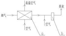
FIG. 1 is a schematic diagram of a flue gas waste heat recovery system for preheating combustion air of a boiler by using conventional flue gas waste heat
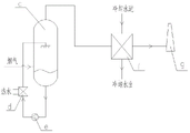
FIG. 2 is a schematic diagram of a flue gas waste heat recovery system for producing hot water by using conventional flue gas waste heat
FIG. 3 is a schematic diagram of a flue gas waste heat deep recovery system based on flue gas pressurization
FIG. 4 is a schematic diagram of a system according to a second embodiment of the present invention
In the figure, 1 is a normal pressure spray tower, 2 is a flue gas compressor, 3 is a high pressure spray tower, 4 is a hydrocyclone, 5 is an expander, 6 is a chimney, 7 is a flash tank, 8 is a first pressure reducing valve, 9 is a first circulating pump, 10 is a second circulating pump, 11 is a second pressure reducing valve, 12 is a third circulating pump, and 13 is a steam compressor; 1a is an atmospheric spray tower demister, 1b is an atmospheric spray tower spray header, 1c is atmospheric spray tower packing, 3a is a high-pressure spray tower demister, 3b is a high-pressure spray tower spray header, 3c is high-pressure spray tower packing, and 7a is a flash tank demister;
a is a preheater, b is a bag-type dust collector, c is a spray tower, d is a hot water heat exchanger, e is a spray pump, f is a cooler, and g is a chimney.
Detailed Description
The invention will be described in further detail with reference to the following figures and specific examples, which are given by way of illustration only and are not intended to limit the scope of the invention.
In the description of the specific embodiments of the present invention, it should be noted that the terms "upper", "lower", "side wall", "vertical", "horizontal", "inside", "outside", and the like indicate orientations or positional relationships based on orientations or positional relationships shown in the drawings, which are merely for convenience of description and simplification of the description, and do not indicate or imply that the device or element referred to must have a particular orientation, be constructed and operated in a particular orientation, and thus, should not be construed as limiting the invention. Furthermore, the terms "first," "second," and "third" are used for descriptive purposes only and are not to be construed as indicating or implying relative importance.
Comparative example one:
the comparative example was analyzed with a waste heat recovery system of a gas boiler of a chemical plant, as shown in fig. 1, which recovers flue gas waste heat by a partition heat exchange method and uses it to preheat boiler inlet air, the gas boiler fuel consumption was 1500Nm3And h, the exhaust temperature of the boiler is about 500 ℃, the steam content of the exhaust gas is about 20%, in order to avoid corrosion of an acid dew point of the preheater a, the temperature of a flue gas outlet of the preheater is controlled to be about 200 ℃, then the temperature of the flue gas is reduced to 80-100 ℃ by a normal-temperature air mixing mode, and the flue gas is discharged to the atmosphere after being subjected to cloth bag dust removal.
It can be seen that the comparative example only realizes sensible heat recovery of high-pressure flue gas (500 ℃ to 200 ℃), and in order to ensure the safe operating temperature of the dust removal equipment, the system also needs to supplement a large amount of air to cool the flue gas, so that the energy consumption of a fan is high, and the flue gas waste heat recovery and utilization efficiency is low; the flue gas outlet position of preheater a often takes place the dust and piles up the scale deposit and block up the flue phenomenon, and the system maintenance work load is great.
Comparative example two:
as shown in fig. 2, after the flue gas of a kiln is primarily recovered by the waste heat boiler, the flue gas waste heat is continuously recovered by a spray gas washing mode to prepare hot water. The temperature of the flue gas entering the spray tower c is 285 ℃, the water vapor content of the flue gas is 15 percent, namely the moisture content of the inlet flue gasH i =176g water vapour/kg dry smoke; the flue gas enters a spray tower c to carry out heat and moisture exchange with spray water, and the balanced adiabatic saturated cooling temperatureT s The temperature is 73.8 ℃, thus obtaining spray water with the temperature of 73.8 ℃; after heat and moisture exchange, the temperature of the flue gas is reduced to 73.8 ℃, the relative humidity is 100 percent, and the moisture content of the flue gas isH o =292g water vapor/kg dry flue gas. And then the saturated wet flue gas is cooled by a cooler f to separate out moisture and then is discharged to the environment.
It can be seen that in the comparative example, the temperature is affected by adiabatic saturation coolingT s The system provides low-temperature hot water with the hot water temperature of 60-65 ℃ to the outside. In addition, the moisture content difference of the flue gas at the inlet and the outlet of the spray tower can find that the moisture content of the flue gas at the outlet of the flue gas is differentH o Greater than the moisture content of the inlet flue gasH i This shows that the system can not effectively recover the latent heat of the water vapor in the flue gas, but the process of humidifying and vaporizing the moisture in the flue gas needs to consume part of the sensible heat of the flue gas, which results in lower heat recovery rate of the system.
The first embodiment is as follows:
as shown in fig. 3, the system for deeply recycling the waste heat of flue gas based on pressurization of flue gas in the embodiment comprises a normal pressure spray tower 1, a flue gas compressor 2, a high pressure spray tower 3, a hydrocyclone 4, an expander 5, a chimney 6, a flash tank 7, a first pressure reducing valve 8, a first circulating pump 9, a second circulating pump 10, a second pressure reducing valve 11, a third circulating pump 12, and a steam compressor 13.
The normal pressure spray tower 1 is a closed tank structure, a high temperature flue gas inlet pipe is connected with a flue gas inlet on the side wall of the normal pressure spray tower 1, a wet flue gas outlet on the top of the normal pressure spray tower is connected with an inlet of the flue gas compressor 2, and the flue gas compressor adopts a double-screw compressor; an outlet of the flue gas compressor is connected with a wet flue gas inlet on the side wall of the high-pressure spray tower 3, a spray water outlet at the bottom of the normal-pressure spray tower is connected with an inlet of the third circulating pump 12, a spray head 1b of the normal-pressure spray tower is connected with a spray water inlet on the side wall of the normal-pressure spray tower, a foam remover 1a of the normal-pressure spray tower is arranged above the inside of the normal-pressure spray tower, a filler 1c of the normal-pressure spray tower is arranged in the middle of the normal-pressure spray tower, the foam remover of the normal-pressure spray tower adopts a wire mesh type foam remover, and the filler of the normal-pressure spray tower adopts ceramic random packing; a flue gas outlet at the top of the high-pressure spray tower is connected with an inlet of the expansion machine 5, an outlet of the expansion machine is connected with a chimney 6, and a condensate discharge port is arranged on a connecting pipeline; a spray water outlet at the bottom of the high-pressure spray tower is connected with an inlet of the second circulating pump 10, an outlet of the second circulating pump is respectively connected with an inlet of a second pressure reducing valve 11, a spray water inlet on the side wall of the high-pressure spray tower and a liquid inlet on the side wall of the hydrocyclone 4, a spray head 3b of the high-pressure spray tower is connected with the spray water inlet on the side wall of the high-pressure spray tower, a high-pressure spray tower demister 3a is arranged above the inside of the high-pressure spray tower, and a high-pressure spray tower filler 3c is arranged in the middle of the high-pressure spray tower; a top exhaust port of the hydrocyclone is connected with an inlet of the expansion machine, and a bottom liquid outlet of the hydrocyclone is connected with an inlet of the first pressure reducing valve 8; an outlet of the first reducing valve is connected with a liquid inlet in the side wall of the flash tank 7, a flash steam outlet in the top of the flash tank is connected with an inlet of the steam compressor 13, and the steam compressor 13 adopts a two-stage centrifugal compressor; a liquid outlet at the bottom of the flash tank is connected with an inlet of the first circulating pump 9, a flash tank demister 7a is arranged in the flash tank, and the flash tank demister is a wire mesh type demister; the outlet of the first circulating pump is connected with the spray water inlet on the side wall of the high-pressure spray tower; the outlet of the second reducing valve is connected with the inlet of a third circulating pump; the outlet of the third circulating pump is connected with the spray water inlet on the side wall of the normal pressure spray tower, and a liquid outlet is arranged on the connecting pipeline. The expansion machine and the flue gas compressor are coaxially mounted to form a compression expansion unit, and the expansion machine is used for recovering high-pressure flue gas expansion work to drag the flue gas compressor to operate.
The working method of the embodiment is as follows:
in this example, the inlet flue gas parameters of comparative example I were used as an example for analysis, and the flue gas temperature was about 500 ℃, the water vapor content was 20%, and the moisture content wasH i The high-temperature flue gas with the mass flow of 22t/h and the steam/kg dry flue gas of not less than 250g enters the normal-pressure spray tower 1 to perform heat-moisture exchange with spray water, and the balanced spray water and the outlet saturated wet flue gas temperature (and the adiabatic saturated cooling temperature)T s1 Equal) is 81.9 ℃, moisture content of flue gasH o1 The water vapor/kg dry flue gas of which the mass flow is 26.65t/h, the pressure ratio is 3 and the power is 1160kW, and the saturated wet flue gas discharged from the normal-pressure spray tower 1 is pressurized to 3bar by a double-screw compressor and enters the high-pressure spray tower 3; the temperature of spray water after the balance of the high-pressure spray tower is increased to 90.0 ℃, the spray water enters a flash tank for flash evaporation after smoke is removed through a hydrocyclone separator, circulating water returns to the high-pressure spray tower again through a first circulating pump after the spray water is flashed to 85 ℃, the flow rate of secondary steam at 85 ℃ obtained by flash evaporation is 7.2t/h, the secondary steam obtained by flash evaporation is pressurized to 2bar through a steam compressor, high-pressure steam is provided for the outside, and the power of the steam compressor is 531 kW; the outlet temperature of the high-pressure spray tower is 90.0 ℃, the mass flow rate is 20.5t/h, and the moisture contentH o2 Entry of saturated humid air with =138g steam/kg dry flue gasThe expansion machine 5 recovers expansion work, the recovery power of the expansion machine is 565kW, and the flue gas after expansion and temperature reduction discharges condensate to the atmospheric environment through a chimney. The flue gas desulfurization is completed in the normal pressure spray tower, and the desulfurization and denitrification products are periodically discharged out of the system through a liquid outlet of an outlet of the third circulating pump. And water is supplemented to the system through a water supplementing port of the normal-pressure spray tower 1, and the water supplementing amount is 5.7 t/h.
In this example, the inlet temperature of the flue gas was 500 ℃ and the moisture content wasH i =250g/kg, mass flow rate 22 t/h; the temperature of the discharged flue gas is 51 ℃, and the moisture content of the discharged flue gas isH o2 And the recovery of 95.5 percent of sensible heat and 44.8 percent of latent heat of the flue gas is realized by =138 g/kg. The system prepares 2bar steam 7.2t/h, the net power consumption is 1126kW, the energy price is 0.5 yuan/kW.h according to the electricity price, the steam price is 250 yuan/t, the annual running time is 8000h, and the annual running cost can be saved by 990 ten thousand yuan. The system has the characteristics of high heat recovery efficiency, no acid dew point corrosion, no extra cooling water consumption, no white smoke in discharge and the like.
Example two:
the system components and the device connection method of this embodiment are as in the first embodiment, and are not described herein again. Except that the expander 5 and the vapor compressor 13 are installed coaxially in the present embodiment, and the expansion work recovered by the expander is used to drive the vapor compressor to operate.
In this example, the inlet flue gas parameters of comparative example I were used as an example for analysis, and the flue gas temperature was about 500 ℃, the water vapor content was 20%, and the moisture content wasH i The high-temperature flue gas with the mass flow of 22t/h and the steam/kg dry flue gas of not less than 250g enters the normal-pressure spray tower 1 to perform heat-moisture exchange with spray water, and the balanced spray water and the outlet saturated wet flue gas temperature (and the adiabatic saturated cooling temperature)T s1 Equal) is 81.9 ℃, moisture content of flue gasH o1 The dry flue gas is pressurized to 4bar by a roots compressor and enters a high-pressure spray tower 3, wherein the saturated wet flue gas is discharged from a normal-pressure spray tower 1, the mass flow of the roots compressor is 26.65t/h, the pressure ratio is 4, and the power is 1525 kW; the temperature of spray water after the balance of the high-pressure spray tower rises to 90 ℃, and the spray water is subjected to smoke removal through a hydrocyclone separatorEntering a flash tank for flash evaporation, returning circulating water to the high-pressure spray tower again through a first circulating pump after the circulating water is flashed to 85 ℃, obtaining secondary steam with the temperature of 85 ℃ through flash evaporation, wherein the flow rate of the secondary steam is 8.6t/h, pressurizing the secondary steam obtained through flash evaporation to 1.1bar through a steam compressor, and providing low-pressure steam to the outside, wherein the power of the steam compressor is 329 kW; the temperature of a flue gas outlet of the high-pressure spray tower is 90 ℃, the mass flow rate is 19.6t/h, and the moisture content isH o2 And (3) saturated wet air of the dry flue gas of =116g steam/kg enters an expansion machine 5 for recovering expansion work, the recovery power of the expansion machine is 655kW, and the water supplement amount is 6.2 t/h.
In this example, the inlet temperature of the flue gas was 500 ℃ and the moisture content wasH i =250g/kg, mass flow 22 t/h; the temperature of the discharged flue gas is 35 ℃, and the moisture content of the discharged flue gas isH o2 And the recovery of 98.1 percent of sensible heat and 53.6 percent of latent heat of the flue gas is realized by =116 g/kg. The low-pressure steam of 1.1bar can be supplied for the outside at 8.6t/h, the net power consumption of the system is 1199kW, the energy price is 0.5 yuan/kW.h according to the electricity price, the steam price is 250 yuan/t, the annual running time is 8000h, and the annual running cost can be saved by 1240 ten thousand yuan. The embodiment has higher economic benefit.
Although the present invention has been described in connection with the accompanying drawings, the present invention is not limited to the above-described embodiments, which are only illustrative and not restrictive, and those skilled in the art can make many modifications without departing from the spirit of the present invention, within the scope of the present invention.
Claims (9)
1. The deep flue gas waste heat recovery system based on flue gas pressurization is characterized by comprising a normal-pressure spray tower, a flue gas compressor, a high-pressure spray tower, a hydrocyclone, an expander, a chimney, a flash tank, a first pressure reducing valve, a first circulating pump, a second pressure reducing valve, a third circulating pump and a steam compressor;
the atmospheric spray tower is of a closed tank structure, the side wall of the atmospheric spray tower is provided with a flue gas inlet, a spray water inlet, a water replenishing port and a medicament adding port, the top of the atmospheric spray tower is provided with a wet flue gas outlet, and the bottom of the atmospheric spray tower is provided with a spray water outlet; the high-pressure spray tower is of a closed tank structure, the side wall of the high-pressure spray tower is provided with a wet flue gas inlet and a spray water inlet, the top of the high-pressure spray tower is provided with a flue gas outlet, and the bottom of the high-pressure spray tower is provided with a spray water outlet; the side wall of the hydrocyclone separator is provided with a liquid inlet, the top of the hydrocyclone separator is provided with an exhaust port, and the bottom of the hydrocyclone separator is provided with a liquid outlet; a liquid inlet is formed in the side wall of the flash tank, a flash steam outlet is formed in the top of the flash tank, and a liquid outlet is formed in the bottom of the flash tank;
the flue gas inlet pipe is connected with a flue gas inlet on the side wall of the normal pressure spray tower, a wet flue gas outlet at the top of the normal pressure spray tower is connected with an inlet of the flue gas compressor, an outlet of the flue gas compressor is connected with a wet flue gas inlet of the high pressure spray tower, and a spray water outlet of the normal pressure spray tower is connected with an inlet of the third circulating pump;
a smoke outlet of the high-pressure spray tower is connected with an inlet of the expansion machine, an outlet of the expansion machine is connected with an air inlet of the chimney, and a condensate discharge port is arranged on a connecting pipeline of the expansion machine and the chimney;
the spray water outlet of the high-pressure spray tower is connected with the inlet of the second circulating pump, and the outlet of the second circulating pump is respectively connected with the inlet of the second pressure reducing valve, the spray water inlet of the high-pressure spray tower and the liquid inlet of the hydrocyclone separator; an exhaust port of the hydrocyclone separator is connected with an inlet of the expansion machine, and a liquid outlet of the hydrocyclone separator is connected with an inlet of the first pressure reducing valve;
an outlet of the first reducing valve is connected with a liquid inlet of the flash tank, a flash steam outlet of the flash tank is connected with an inlet of the steam compressor, and a liquid outlet of the flash tank is connected with an inlet of the first circulating pump; the outlet of the first circulating pump is connected with the spray water inlet of the high-pressure spray tower; an outlet of the second pressure reducing valve is connected with an inlet of a third circulating pump; the outlet of the third circulating pump is connected with the spray water inlet of the normal pressure spray tower, and a liquid discharge port is arranged on a connecting pipeline of the third circulating pump and the spray water inlet of the normal pressure spray tower.
2. The deep recycling flue gas waste heat system based on flue gas pressurization as claimed in claim 1, wherein an atmospheric spray tower demister, an atmospheric spray tower spray header and an atmospheric spray tower filler are arranged inside the atmospheric spray tower, and the atmospheric spray tower spray header is connected with a spray water inlet of the atmospheric spray tower; the normal pressure spray tower demister adopts a wire mesh demister or a baffle plate type demister.
3. The deep recovery flue gas waste heat system based on flue gas pressurization as claimed in claim 2, wherein a high-pressure spray tower demister, a high-pressure spray tower spray header and a high-pressure spray tower filler are arranged inside the high-pressure spray tower, and the high-pressure spray tower spray header is connected with a spray water inlet of the high-pressure spray tower; the high-pressure spray tower demister adopts a wire mesh demister or a baffle plate type demister.
4. The deep flue gas waste heat recovery system based on flue gas pressurization as claimed in claim 3, wherein the normal pressure spray tower packing and the high pressure spray tower packing are corrosion-resistant random packing or regular packing, and the packing is made of metal, ceramic or plastic.
5. The deep recovery flue gas waste heat system based on flue gas pressurization as claimed in claim 4, wherein a flash tank demister is arranged inside the flash tank, and the flash tank demister is a wire mesh demister or a baffle type demister.
6. The deep recovery flue gas waste heat system based on flue gas pressurization as claimed in claim 5, wherein the flue gas compressor adopts a single-stage or multi-stage compression mode, and the flue gas compressor is in the form of a piston compressor, a roots compressor, a screw compressor or a centrifugal compressor.
7. The deep recovery flue gas waste heat system based on flue gas pressurization as claimed in claim 6, wherein the vapor compressor adopts a single-stage or multi-stage compression mode, and the vapor compressor is in the form of a piston compressor, a roots compressor, a screw compressor or a centrifugal compressor.
8. The deep recycling flue gas waste heat system based on flue gas pressurization as claimed in claim 7, wherein the expander is installed coaxially with the flue gas compressor or the vapor compressor, and the recycling high-pressure flue gas expansion function is used for driving the flue gas compressor or the vapor compressor installed coaxially with the expander to operate.
9. The working method of the deep recovery flue gas waste heat system based on flue gas pressurization as claimed in any one of claims 1 to 8, wherein high temperature flue gas enters an atmospheric spray tower to perform heat and humidity exchange with spray water, high temperature sensible heat of the flue gas is recovered and the flue gas is humidified, and the temperature of the spray water is balanced at adiabatic saturated cooling temperatureT s And discharge temperature ofT s The saturated wet flue gas enters the high-pressure spray tower after passing through the flue gas compressor, the moisture content of the flue gas is reduced after the pressure is increased, moisture is separated out from the wet flue gas, and latent heat is released from condensate to heat circulating water in the high-pressure spray tower; spraying water in the high-pressure spraying tower returns to the normal-pressure spraying tower through a part of a second circulating pump, the other part of spraying water enters a hydrocyclone separator to be separated from entrained flue gas, the spraying water is decompressed by a first pressure reducing valve and enters a flash tank to be flashed and cooled, secondary water vapor obtained by flashing is compressed and pressurized by a vapor compressor and then is externally supplied with high-pressure vapor; the circulating water after being subjected to flash evaporation and temperature reduction in the flash evaporation tank returns to the high-pressure spray tower again through the first circulating pump to absorb heat and raise the temperature; the flue gas discharged by the high-pressure spray tower and the flue gas separated by the hydrocyclone separator enter an expansion machine, and the recovered expansion work is used for driving a flue gas compressor or a steam compressor; after the high-pressure flue gas does work outwards through the expansion machine, the temperature is reduced, and part of water is separated out and changed into unsaturated flue gas, and then the unsaturated flue gas is discharged to the atmosphere through a chimney; and (4) supplementing water to the system at the normal-pressure spray tower, supplementing a desulfurization agent, and periodically discharging a flue gas desulfurization byproduct concentrated solution out of the system through a liquid outlet.
Priority Applications (1)
| Application Number | Priority Date | Filing Date | Title |
|---|---|---|---|
| CN202210386886.2A CN114459044B (en) | 2022-04-14 | 2022-04-14 | System and method for deeply recycling flue gas waste heat based on flue gas pressurization |
Applications Claiming Priority (1)
| Application Number | Priority Date | Filing Date | Title |
|---|---|---|---|
| CN202210386886.2A CN114459044B (en) | 2022-04-14 | 2022-04-14 | System and method for deeply recycling flue gas waste heat based on flue gas pressurization |
Publications (2)
| Publication Number | Publication Date |
|---|---|
| CN114459044A CN114459044A (en) | 2022-05-10 |
| CN114459044B true CN114459044B (en) | 2022-07-08 |
Family
ID=81418648
Family Applications (1)
| Application Number | Title | Priority Date | Filing Date |
|---|---|---|---|
| CN202210386886.2A Active CN114459044B (en) | 2022-04-14 | 2022-04-14 | System and method for deeply recycling flue gas waste heat based on flue gas pressurization |
Country Status (1)
| Country | Link |
|---|---|
| CN (1) | CN114459044B (en) |
Family Cites Families (8)
| Publication number | Priority date | Publication date | Assignee | Title |
|---|---|---|---|---|
| US7802430B1 (en) * | 2009-03-20 | 2010-09-28 | Sha William T | Condensers efficiency through novel PCS technology |
| CN202315681U (en) * | 2011-11-17 | 2012-07-11 | 刘晓敏 | Sulfur absorbing apparatus in flue gas desulfurization system |
| CN107694304A (en) * | 2016-08-08 | 2018-02-16 | 无锡市曜通环保机械有限公司 | A kind of incinerator smoke denitration wet desulphurization electric dust collector |
| CN106731443A (en) * | 2016-12-29 | 2017-05-31 | 山东大学 | Reduce coal combustion flue gas CO2Trap the flue gas pretreatment system of energy consumption |
| JP6740185B2 (en) * | 2017-07-11 | 2020-08-12 | 月島機械株式会社 | Exhaust gas desulfurization method in pressurized fluidized-bed reactor system and pressurized fluidized-bed reactor system |
| CN109681281B (en) * | 2019-01-25 | 2024-01-26 | 清华大学 | Biomass cogeneration system capable of simultaneously recovering exhaust steam and flue gas waste heat |
| CN215411804U (en) * | 2020-12-31 | 2022-01-04 | 中国石油化工股份有限公司 | Process system for deep upgrading and utilizing flue gas waste heat |
| CN112879940B (en) * | 2021-02-22 | 2022-08-23 | 西安热工研究院有限公司 | Low-temperature flue gas latent heat recovery and comprehensive utilization system and method |
-
2022
- 2022-04-14 CN CN202210386886.2A patent/CN114459044B/en active Active
Also Published As
| Publication number | Publication date |
|---|---|
| CN114459044A (en) | 2022-05-10 |
Similar Documents
| Publication | Publication Date | Title |
|---|---|---|
| CN107355371B (en) | Efficient compressed air energy storage system and method | |
| CN110864342A (en) | Water replenishing system and method for indirectly heating heat supply network by using low-temperature waste heat of flue gas | |
| CN108413637B (en) | A kind of recycling of industrial smoke waste heat and dehumidification system | |
| CN111594813A (en) | Combined-cycle efficient clean power generation device and method utilizing low-temperature latent heat of flue gas | |
| CN202108549U (en) | Integrated system for coal generation, carbon dioxide collection and heating | |
| CN109432935B (en) | System for deeply eliminating white smoke of wet desulphurization flue gas | |
| CN112944726B (en) | Open type heat absorption heating system with high heat storage density | |
| CN113091477B (en) | Wet flue gas source heat pump system for controlling input flue gas pressure | |
| CN113932208A (en) | Multi-heat-source heat pump high-temperature steam supply system and working method thereof | |
| CN113998751A (en) | System for desulfurization slurry flash distillation is carried hot water intaking | |
| CN211119603U (en) | Water replenishing system for indirectly heating heat supply network by using low-temperature waste heat of flue gas | |
| CN114459044B (en) | System and method for deeply recycling flue gas waste heat based on flue gas pressurization | |
| CN102278205A (en) | Combined cycle method capable of being used for distributed air and fuel humidified gas turbine | |
| CN202511307U (en) | Compound phase change heat exchange system for recycling boiler flue gas waste heat | |
| CN201723313U (en) | Gas turbine combined cycling device for distributed air and fuel humidification | |
| CN201760225U (en) | Site treating and using system of natural gas and gas fume | |
| CN110864324A (en) | System and method for improving boiler efficiency by using low-temperature waste heat of flue gas | |
| CN207113238U (en) | A kind of double low-temperature receiver gas fired-boiler Latent heat advanced recycling systems | |
| CN105314611A (en) | Dilute nitric acid device adopting double pressure method | |
| CN205187873U (en) | Dual pressure dilute nitric acid device | |
| CN114001486A (en) | Flash evaporation hot water extraction system based on open absorption heat pump | |
| CN210831925U (en) | Deep recovery device for exhaust smoke waste heat and moisture of power station boiler | |
| CN113483347A (en) | Working method of white smoke eliminating device with cooperation of flue gas waste heat and moisture recovery | |
| CN211146548U (en) | System for improving boiler efficiency by utilizing low-temperature waste heat of flue gas | |
| CN216282135U (en) | Flash evaporation hot water extraction system based on open absorption heat pump |
Legal Events
| Date | Code | Title | Description |
|---|---|---|---|
| PB01 | Publication | ||
| PB01 | Publication | ||
| SE01 | Entry into force of request for substantive examination | ||
| SE01 | Entry into force of request for substantive examination | ||
| GR01 | Patent grant | ||
| GR01 | Patent grant |