CN114458564B - Hall thruster ring type partial pressure gas path insulation structure - Google Patents
Hall thruster ring type partial pressure gas path insulation structure Download PDFInfo
- Publication number
- CN114458564B CN114458564B CN202210380575.5A CN202210380575A CN114458564B CN 114458564 B CN114458564 B CN 114458564B CN 202210380575 A CN202210380575 A CN 202210380575A CN 114458564 B CN114458564 B CN 114458564B
- Authority
- CN
- China
- Prior art keywords
- gas
- path
- annular
- gas path
- annular gas
- Prior art date
- Legal status (The legal status is an assumption and is not a legal conclusion. Google has not performed a legal analysis and makes no representation as to the accuracy of the status listed.)
- Active
Links
Images


Classifications
-
- F—MECHANICAL ENGINEERING; LIGHTING; HEATING; WEAPONS; BLASTING
- F03—MACHINES OR ENGINES FOR LIQUIDS; WIND, SPRING, OR WEIGHT MOTORS; PRODUCING MECHANICAL POWER OR A REACTIVE PROPULSIVE THRUST, NOT OTHERWISE PROVIDED FOR
- F03H—PRODUCING A REACTIVE PROPULSIVE THRUST, NOT OTHERWISE PROVIDED FOR
- F03H1/00—Using plasma to produce a reactive propulsive thrust
- F03H1/0037—Electrostatic ion thrusters
-
- F—MECHANICAL ENGINEERING; LIGHTING; HEATING; WEAPONS; BLASTING
- F03—MACHINES OR ENGINES FOR LIQUIDS; WIND, SPRING, OR WEIGHT MOTORS; PRODUCING MECHANICAL POWER OR A REACTIVE PROPULSIVE THRUST, NOT OTHERWISE PROVIDED FOR
- F03H—PRODUCING A REACTIVE PROPULSIVE THRUST, NOT OTHERWISE PROVIDED FOR
- F03H1/00—Using plasma to produce a reactive propulsive thrust
- F03H1/0006—Details applicable to different types of plasma thrusters
Landscapes
- Engineering & Computer Science (AREA)
- Chemical & Material Sciences (AREA)
- Combustion & Propulsion (AREA)
- Physics & Mathematics (AREA)
- Plasma & Fusion (AREA)
- Mechanical Engineering (AREA)
- General Engineering & Computer Science (AREA)
- Plasma Technology (AREA)
Abstract
The invention discloses a ring-type partial pressure gas path insulation structure of a Hall thruster, which comprises a gas inlet pipe, an insulator body and a gas outlet pipe, wherein a buffer cavity, a ring-shaped gas path and a metal spacer mesh are arranged in the insulator body, the insulator body is provided with a cylindrical buffer cavity communicated with an inner cavity of the gas inlet pipe, the buffer cavity is communicated with the ring-shaped gas path on the outer side, the ring-shaped gas path is in a ring shape, a plurality of metal spacer meshes are arranged on the ring-shaped gas path at intervals, gas enters the buffer cavity through the gas inlet pipe to disturb uniform deceleration and then is introduced into the ring-shaped gas path, the gas is subjected to partial pressure through the plurality of metal spacer meshes arranged at intervals and then is discharged through the gas outlet pipe, and in the gas circulation process, the plurality of metal spacer meshes are reused as metal electrodes. The invention provides a Hall thruster ring type partial pressure gas path insulation structure which increases the flow velocity of working medium gas and improves the pressure resistance.
Description
Technical Field
The invention relates to the technical field of Hall thrusters, in particular to a ring type partial pressure gas path insulation structure of a Hall thruster.
Background
The Hall thruster is also called as a Hall effect thruster, the propellant is accelerated by an electric field in the thruster, electrons are restrained in a magnetic field by the Hall thruster, the propellant is ionized by the electrons, accelerated ions generate thrust, and the ions in the plume are neutralized.
The Hall thruster is an advanced electric propulsion device, is widely applied to the field of satellite position keeping and attitude control, and becomes one of the first-choice propulsion devices of future space vehicles due to the advantages of simple structure, high specific impulse, high efficiency and the like. Different from the insulation design of conventional electrical equipment working in an atmospheric environment, the Hall thruster is used as special electrical equipment working in a high-vacuum environment and a plasma environment, and the research and design of electrical insulation are more specialized due to the fact that the mean free path of charged particles in vacuum is large.
When the Hall electric propulsion system works, an air circuit electric insulation structure is generally adopted to connect the storage and supply unit and the thruster, so that smoothness of air supply is guaranteed, and high-voltage insulation can be realized. The xenon pressure in a general gas supply pipeline is 102~103The Pa-magnitude rarefied gas is easy to generate ionization breakdown to cause insulation failure; meanwhile, the working environment of the thruster is a complex environment surrounded by high vacuum and plasma, and the outer surface of the ceramic pipeline is polluted to cause structural insulation failure so as to generate electric conduction.
The current gas circuit insulation structure mainly adopts the multistage partial pressure structure of axial, through increasing its insulating progression, improves gas circuit electrical insulator's compressive capacity, and the influence that brings thereupon is: the axial distance is increased, so that the mechanical resistance of the cable is poor; meanwhile, the ceramic outside adopts a protective cover design to reduce plasma bombardment pollution, the mounting structure is complex, the insulating property of the external ceramic is reduced under long-term work, and the ceramic cannot effectively work for a long time
Therefore, aiming at the requirement of high pressure resistance of the air supply pipeline of the hall thruster, in the structural design of the air circuit insulator, how to adopt multi-stage partial pressure to realize high pressure resistance and solve the problem of resistance engineering of the structure, and the external ceramic is not polluted and punctured under the long-term working condition, which is a technical problem to be solved urgently by technical personnel in the field.
Disclosure of Invention
The invention aims to provide a ring-type partial pressure gas path insulation structure of a Hall thruster, aiming at solving the problems in the prior art, and improving the mechanical resistance of a gas path insulator while meeting the requirement of voltage resistance.
Therefore, the above purpose of the invention is realized by the following technical scheme:
the utility model provides a hall thruster ring type partial pressure gas circuit insulation system which characterized in that: including intake pipe, insulator body and outlet duct, including cushion chamber, cyclic annular gas circuit and metal separation net in the insulator body, the insulator body is in the columniform cushion chamber that the inner chamber of intercommunication intake pipe set up, the cyclic annular gas circuit in the cushion chamber intercommunication outside, cyclic annular gas circuit is the ring form, the interval sets up a plurality of metals on the cyclic annular gas circuit and separates the net, gaseous get into the cushion chamber through the intake pipe and disturb even deceleration back, let in cyclic annular gas circuit, a plurality of metals that set up through the interval separate the net partial pressure after lead to out through the outlet duct, at the gas circulation in-process, a plurality of metals separate the multiplexing metal electrode that is of net.
While adopting the technical scheme, the invention also adopts or combines the following technical scheme:
as a preferred technical scheme of the invention: the insulator body comprises an insulating ceramic ring and a ceramic cover plate, the insulating ceramic ring comprises a cylindrical buffer cavity arranged in the center and an external annular gas path, and the buffer cavity and the annular gas path are concentrically arranged and have the same height; the buffer cavity is connected with the front end of the annular gas path through the flow guide hole; the annular gas path is a non-closed annular channel separated by a ceramic partition plate, a plurality of stages of metal partition nets are arranged on the annular gas path at equal intervals, and the bottom of the tail end of the annular gas path is provided with a gas outlet hole which is connected with a gas outlet pipe through the gas outlet hole; the ceramic cover plate is a circular cover plate, a round hole is formed in the center of the ceramic cover plate and is connected with the air inlet pipeline through the round hole, and the ceramic cover plate and the insulating ceramic ring have the same outer diameter.
As a preferred technical scheme of the invention: the insulating ceramic ring is provided with a flow guide hole between the wall of the annular gas circuit and the wall of the buffer cavity, one side of the annular gas circuit communicated with the flow guide hole is provided with a baffle plate, the other side of the baffle plate is provided with a gas outlet hole, the gas outlet hole is connected with a gas outlet pipe, and gas is led out from the gas outlet hole after being led into the annular gas circuit through the flow guide hole to form a one-way circulation channel.
As a preferred technical scheme of the invention: the insulating ceramic ring is provided with a clamping groove on the annular gas path, and a metal separation net is inserted into the clamping groove; the metal separation net is made of stainless steel.
As a preferred technical scheme of the invention: the insulating ceramic ring is annular, and the insulating ceramic ring and the ceramic cover plate form a disc shape of the insulator body after being sealed.
As a preferred technical scheme of the invention: the insulating ceramic ring and the air outlet pipe are sealed by brazing;
the ceramic cover plate and the air inlet pipe are sealed by brazing.
As a preferred technical scheme of the invention: reynolds number Re of gas in annular gas path1The calculation formula is as follows:

wherein q ismIs the gas mass flow rate, and the unit is mg/s; d is the equivalent diameter of the annular gas path in m, A is the cross-sectional area of the annular gas path in m2Eta is viscosity coefficient of gas in kg · m-1·s-1;
The equivalent diameter D of the annular gas path satisfies the following relation:

wherein R is2Is the inner diameter of the annular gas path, and the unit is m; r is3Is the outer diameter in m; h is height in m;
the cross-sectional area A of the annular gas path satisfies the following relationship:
A=(R3-R2)h (10)
substituting the formula (9) and the formula (10) into the formula (8), further obtaining a calculation formula of the Reynolds number of the gas in the annular gas path as follows:

the calculation formula of the Kenun increase coefficient of the gas in the annular gas path is as follows:

wherein: kn1The gas is a gas of an annular gas path with a Knoop increasing coefficient; the unit is m, and the average free path of gas in the annular gas path is;
mean free path of gas under the same gas The following formula is satisfied:

wherein σ is a gas collision cross section and has a unit of m2(ii) a n is the gas density in units of units/m3;
The density of the gas in the annular gas path satisfies the following formula:

wherein n is1Is the gas density in units of units/m3; The average thermal movement speed of the gas is given as m/s; m is the gas molecular mass in kg;
the relationship between the pressure in the annular gas path and the gas density is as follows:
P1=n1kT (15)
in the formula, P1Is the gas pressure in Pa; k is Boltzmann constant, and the unit is J/K; t is the gas temperature in K;
according to the ionization performance requirement of gas in a discharge channel of the Hall thruster, the pressure of the gas at an inlet of the discharge channel is 100-1000 Pa, and meanwhile, the gas in the annular gas needs to meet the viscous flow state, namely:
Re1<1200

100<P1<1000 (16)
determining the inner diameter R of the annular gas path by combining the formulas (8) to (16)2Outer diameter R3And the height h, and the setting of the parameter values of the annular gas circuit realizes that the gas in the gas circuit meets the viscous flow characteristic, thereby ensuring the realization of the grading pressure resistance.
As a preferred technical scheme of the invention: the maximum withstand voltage of the gas path insulation structure is VmaxDesign, setting the anode high voltage as VdAnd if the working margin is delta V, the maximum withstand voltage of the gas path insulator meets the following relation:
Vmax=Vd+ΔV (1)
based on the principle of potential superposition, the high-voltage resistance parameter is realized through multi-stage voltage division, namely, in a single-connection ventilation circuit, each stage of electrode can resist voltage V by setting N stages of electrodes0Then the total voltage withstanding parameter V1The following relationship is satisfied:
V1=NV0 (2)
aiming at xenon working medium, in a viscous flow state, when the electrode is made of iron material, the lowest withstand voltage value of two poles is about 150V, therefore, the stage number N of the metal separation net electrode arranged in the annular gas path satisfies the following relation:
150N≥Vmax (3)
the minimum number of stages NminComprises the following steps:

when N is presentminWhen there is remainder, then NminAdding 1; the number N of the metal separation nets is more than or equal to Nmin;
The adjacent metal separation nets need insulation treatment and are arranged with two metal separation netsThe small distance is d, the maximum number of the metal grids is NmaxThe following relationship is satisfied:

wherein L is the length of the gas transmission path and has the unit of m; considering point discharge between metal grids, a ceramic process and the like, the minimum distance is 2mm, and in the annular gas path, a gas transmission path meets the following relation:

wherein, the average radius of the annular gas path is m; according to the analysis, the number N of the metal separation nets is located at NminAnd NmaxIn the meantime.
As a preferred technical scheme of the invention: the gas in the buffer cavity needs to be in a viscous flow state, the gas flowing in from the gas inlet pipe has strong speed and certain non-uniformity, the flow speed of the gas is slowed down through the buffer cavity 201, the uniformity of the gas is increased, and the Reynolds number calculation formula of the gas in the buffer cavity is as follows:

wherein R is1Is the radius of the buffer cavity, and the unit is m; q. q ofmIs the gas mass flow rate, and the unit is mg/s; eta is the viscosity coefficient of gas in kg.m-1·s-1;Re2The gas Reynolds number of the buffer cavity;
radius of the buffer chamber R1The relationship with the Knoop coefficient of the internal gas is as follows:

wherein, the unit is m, and the average free path of the gas in the buffer cavity is; kn2The Kenun increase coefficient of the gas in the buffer cavity;
the relationship between the gas density in the buffer chamber and the mass flow of the inlet pipe is as follows:

wherein n is2Is the gas density of the buffer chamber, and has unit of unit/m3;
According to the requirement of viscous flow, the Reynolds number and the Kenuncai coefficient of the gas in the buffer cavity simultaneously meet the following requirements:
Re2<1200

combining the formulas (17) to (20) to further obtain the radius R of the buffer cavity1The following ranges are satisfied:

thereby obtaining the value of the radius of the buffer cavity.
According to the air path partial pressure insulation structure of the Hall thruster air supply pipeline, an annular air path is adopted, an air transmission path is prolonged, and a metal separation net is arranged on the annular air path along the circumferential direction, so that multi-stage partial pressure is realized; analyzing the relation between the gas state and the structure size of the annular gas path and the buffer cavity to obtain the design criteria that the gas meets the key sizes such as the inner radius, the outer radius and the height of the annular gas path and the radius and the height of the buffer cavity in the viscous flow state; the length-diameter ratio of the gas path insulator body is controlled, so that the structural mechanical resistance of the gas path insulator body is improved; according to the anode voltage parameter of the thruster, giving a withstand voltage value of the gas insulator, and calculating the number and layout mode of the metal separation nets; and (3) combining the space size of the magnetic conduction base of the Hall thruster and the air distributor, and giving the matching relation of the outline size of the air path insulator, so that the air path insulator is arranged inside the thruster. The ring-type partial pressure gas insulation structure designed by the invention meets the basic requirement of high voltage resistance, has compact structure and enhanced mechanical resistance, and solves the problem of poor mechanical resistance caused by axial partial pressure of the existing gas path insulator; meanwhile, the gas path insulator is arranged in the thruster, plasma pollution in the external environment is avoided, and long-term working reliability of the gas path insulator is improved.
Drawings
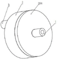
FIG. 1 is an axial view of an insulating structure of a ring-type partial pressure gas path of a Hall thruster of the invention;
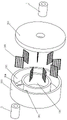
FIG. 2 is an exploded view of the Hall thruster ring type partial pressure gas path insulation structure of the present invention;
FIG. 3 is a cross-sectional view of the ring-type pressure-dividing air path insulation structure of the Hall thruster of the present invention;
FIG. 4 is a partial schematic view of the ring-type voltage-dividing gas path insulation structure of the Hall thruster of the present invention;
in the drawings: an air inlet pipe 1; an insulator body 2; a buffer chamber 201; an annular gas path 202; a bottom plate 205; an insulating ceramic ring 203; a ceramic cover plate 204; a flow guide hole 205; a baffle 206; an air outlet 207; a metal screen 208; and an air outlet pipe 5.
Detailed Description
The invention is described in further detail with reference to the figures and specific embodiments.
Example 1
As shown in fig. 1-4, the ring-type partial pressure gas path insulation structure of the hall thruster of the present invention includes a gas inlet pipe 1, an insulator body 2, and a gas outlet pipe 5, where the insulator body 2 includes a buffer chamber 201, an annular gas path 202, and a metal spacer net 208, the insulator body 2 is provided with a cylindrical buffer chamber 201 in an inner cavity communicated with the gas inlet pipe 1, the cylindrical buffer chamber 201 is communicated with the outer annular gas path 202, the annular gas path is annular, a plurality of metal spacer nets 208 are provided at intervals on the annular gas path 202, gas enters the buffer chamber 201 through the gas inlet pipe 1 to disturb uniform speed reduction, then is introduced into the annular gas path 202, is subjected to partial pressure by the plurality of metal spacer nets 208 provided at intervals, and is discharged through the gas outlet pipe 5, and in the gas circulation process, the plurality of metal spacer nets 208 are reused as metal electrodes. The metal grid not only ventilates, still acts as partial pressure electrode.
Compared with the axial gas path structure of the existing gas path insulator, the ring-type partial pressure gas path insulation structure of the Hall thruster has the advantages that the gas path is designed into a ring-shaped structure, so that the gas transmission path can be obviously prolonged, the length-diameter ratio of the gas path insulator is effectively controlled, and the mechanical resistance of the gas path insulator is improved; a series of metal separation nets are uniformly arranged in the annular gas circuit to serve as grading electrodes, the lowest breakdown voltage is lower between every two electrodes, and the sum of the voltages between the electrodes is equal to the total withstand voltage value according to the multi-stage voltage division principle. Different pressure-resistant requirements are realized by controlling the quantity of the metal separation nets. In order to better realize the pressure resistance, a buffer cavity structure is designed in front of the annular gas path, the flow rate of gas is reduced, and gas homogenization is realized, so that the pressure resistance reliability is improved, and the buffer cavity and the annular gas path are in concentric circle layout, are disc-shaped and have compact structures. The annular partial pressure gas path insulation structure of the Hall thruster can meet the pressure resistance requirement, simultaneously improve the mechanical resistance of the structure, and solve the problem of poor mechanical resistance caused by the increase of the axial structure due to the axial partial pressure of the existing gas path insulator.
The insulator body 2 comprises an insulating ceramic ring 203 and a ceramic cover plate 204, the insulating ceramic ring 203 comprises a cylindrical buffer cavity 201 arranged in the center and an external annular gas path 202, and the buffer cavity 201 and the annular gas path 202 are concentrically arranged and have the same height; the buffer cavity 201 is connected with the front end of the annular gas path 202 through a flow guide hole 205; the annular gas path 202 is a non-closed annular channel separated by a ceramic partition plate, a plurality of stages of metal partition nets 208 are arranged on the annular gas path at equal intervals, and a gas outlet hole 207 is arranged at the bottom of the tail end of the annular gas path and is connected with the gas outlet pipe 3 through the gas outlet hole 207; the ceramic cover plate 201 is a circular cover plate, a circular hole is formed in the center of the ceramic cover plate, the ceramic cover plate is connected with the air inlet pipeline 1 through the circular hole, and the ceramic cover plate 204 and the insulating ceramic ring 203 have the same outer diameter.
The insulating ceramic ring 203 is provided with a flow guide hole 205 between the wall of the annular gas path 202 and the buffer cavity 201, one side of the annular gas path 202 communicated with the flow guide hole 205 is provided with a baffle 206, the other side of the baffle 206 is provided with a gas outlet hole 207, the gas outlet hole 207 is connected with the gas outlet pipe 5, and gas is introduced into the annular gas path 202 through the flow guide hole 205 and then is discharged from the gas outlet hole 207 to form a one-way circulation channel. The baffle 206 is made of ceramic.
In the invention, the buffer cavity 201 is arranged in the middle of the annular gas path 202, the annular gas path 202 is annular, the annular gas path 202 utilizes an annular path to prolong the length of the gas path required by partial pressure, and after the working medium gas enters the buffer cavity 201, the working medium gas can achieve better turbulence and deceleration effects by virtue of a cylindrical structure and the arrangement of the side wall surface diversion holes, so that the flow rate of the working medium gas entering the annular gas path 202 with partial pressure is more stable, the gas quality is more uniform, and the stability of the gas path partial pressure is improved. In the invention, the ceramic cover plate 204 and the insulating ceramic ring 203 are made of A95 alumina ceramic material; a round hole is formed in the center of the ceramic cover plate 204 and is connected with the air inlet pipe 1 through the round hole, wherein the ceramic cover plate 204 and the air inlet pipe 1 are sealed by brazing; the ceramic cover plate 204 has the same outer diameter as the insulating ceramic ring 203, and is sealed by high temperature ceramic paste.
In the invention, the annular design of the annular gas path 202 and the concentric design of the annular gas path and the annular buffer cavity 201 provide a realization condition for the vertical arrangement of the circular holes of the gas inlet pipe 1 and the gas inlet thereof and the flow guide holes 205 on the side wall in the gas inlet direction, and the vertical arrangement of the circular holes of the gas inlet pipe 1 and the gas inlet thereof and the flow guide holes 205 on the side wall in the gas inlet direction provides a bent gas path, thereby prolonging the mixing and disturbing path, reducing the flow velocity of the working medium gas in the gas inlet pipe 1 and simultaneously improving the mixing and disturbing effect. Particularly, the buffer cavity 201 is disposed on the inner wall of the annular gas path 202, and under the condition that the overall structural envelope is not changed, two functional areas of the buffer cavity and the annular gas path are separated.
According to the annular pressure-dividing gas path insulation structure for the Hall thruster, working medium gas enters the insulator body 2 from the gas inlet pipe 1, is decelerated and homogenized in the buffer cavity 201 at first, then enters the front end of the annular gas path 202 through the flow guide holes 205, is subjected to pressure division through the multi-stage metal separation nets 208 arranged at equal intervals along the circumferential direction in sequence, touches the baffle at the tail end of the annular gas path and is blocked, and finally flows out from the gas outlet pipe 3 to form one-way circulation; the mode of utilizing the ascending length partial pressure of axial direction among the prior art has been changed, divide pressure on cyclic annular gas circuit, utilize ceramic insulating ring to be circular annular or the design of the circular cavity in disc type shape laminating hall thruster bottom of spiral, overall structure envelope is little, need not additionally to set up complicated installing support and can place in the magnetic conduction base in, be applicable to small structure hall thruster internally mounted, thoroughly avoid the plasma pollution among the external environment, solved and leaded to the risk of puncturing because of the outside ceramic surface pollution of long-term work.
The number of the metal separation nets 208 in the ring-type partial pressure gas path insulation structure of the hall thruster is related to the voltage withstanding parameters of the ring-type partial pressure gas path insulation structure and the lowest voltage withstanding value of the adjacent electrodes, and the specific relationship is as follows:
the maximum withstand voltage of the gas path insulation structure is VmaxDesign, setting the anode high voltage as VdAnd if the working margin is delta V, the maximum withstand voltage of the gas path insulator meets the following relation:
Vmax=Vd+ΔV (1)
based on the potential superposition principle, high-voltage-resistant parameters are realized through multi-stage voltage division. That is, in the single-connected gas passage, by setting N stages of electrodes, each stage of electrodes can withstand voltage V0Then the total voltage withstanding parameter V1The following relationship is satisfied:
V1=NV0 (2)
aiming at xenon working medium, in a viscous flow state, when the electrode is made of iron material, the lowest withstand voltage value of two poles is about 150V, therefore, the stage number N of the metal separation net electrode arranged in the annular gas path satisfies the following relation:
150N≥Vmax (3)
the minimum number of stages NminComprises the following steps:

when N is presentminWhen there is remainder, then NminAdding 1; the number N of the metal separation nets is more than or equal to Nmin;
The adjacent metal separation nets need insulation treatment, the minimum distance between the two metal separation nets is d, and the maximum number N of the metal gridsmaxThe following relationship is satisfied:

wherein L is the length of the gas transmission path and has the unit of m; considering the point discharge between the metal grids, the ceramic process and the like, the minimum distance is generally 2 mm. In the annular gas circuit, the gas transmission path satisfies the following relation:

wherein, the average radius of the annular gas path is m; according to the analysis, the number N of the metal separation nets is located at NminAnd NmaxIn the meantime.
After the number of the metal separation nets is determined, the metal separation nets are arranged in the annular gas path at equal included angles along the radial direction, and the included angle theta between every two metal separation nets satisfies the following formula:

in the invention, in order to ensure that the gas in the annular gas path is viscous flow so as to ensure the pressure resistance of the metal mesh electrode, the structural size of the annular gas path needs to be reasonably designed. Reynolds number Re of gas in annular gas path1The calculation formula is as follows:

wherein q ismIs the gas mass flow rate, and the unit is mg/s; d is the equivalent diameter of the annular gas path in m, A is the cross-sectional area of the annular gas path in m2Eta is the viscosity coefficient of gas in kg.m-1·s-1;
The equivalent diameter D of the annular gas path satisfies the following relationship:

wherein R is2Is the inner diameter of the annular gas path, and the unit is m; r3Is the outer diameter in m; h is height in m;
the cross-sectional area A of the annular gas path satisfies the following relationship:
A=(R3-R2)h (10)
substituting the formula (9) and the formula (10) into the formula (8), further obtaining a calculation formula of the Reynolds number of the gas in the annular gas path as follows:

the calculation formula of the Kenun increase coefficient of the gas in the annular gas path is as follows:

wherein: kn1The gas is a gas of an annular gas path with a Knoop increasing coefficient; the unit is m, and the average free path of gas in the annular gas path is;
mean free path of gas under the same gas The following formula is satisfied:

wherein σ is a gas collision cross section and has a unit of m2(ii) a n is the gas density in units of units/m3;
The density of the gas in the annular gas path satisfies the following formula:

wherein n is1Is the gas density in units of units/m3; The average thermal movement speed of the gas is given as m/s; m is the gas molecular mass in kg;
the relationship between the pressure in the annular gas path and the gas density is as follows:
P1=n1kT (15)
in the formula, P1Is the gas pressure in Pa; k is Boltzmann constant, and the unit is J/K; t is the gas temperature in K;
according to the ionization performance requirement of gas in a discharge channel of the Hall thruster, the pressure of gas at an inlet of the discharge channel is 100-1000 Pa, and meanwhile, the gas in annular gas needs to meet the viscous flow state, namely:
Re1<1200

100<P1<1000 (16)
determining the inner diameter R of the annular gas path by combining the formulas (8) to (16)2Outer diameter R3And the value of the height h. By controlling the sizes, the gas in the annular gas path meets the viscous flow characteristic, so that the realization of the grading pressure resistance is ensured.
In the same way, the size of the buffer cavity needs to be reasonably designed, and the gas in the buffer cavity needs to be in a viscous flow state. The gas flowing in from the gas inlet pipe 1 has a strong speed and certain non-uniformity, the flow speed of the gas is reduced through the buffer cavity 201, the uniformity of the gas is improved, and the pressure resistance of the gas path insulator is improved.
The Reynolds number of the gas in the buffer cavity is calculated according to the following formula:

wherein R is1Is the radius of the buffer cavity, and the unit is m; q. q.smIs the gas mass flow rate, and the unit is mg/s; eta is viscosity coefficient of gas in kg.m-1·s-1;Re2The gas Reynolds number of the buffer cavity;
radius of the buffer chamber R1The relationship with the Knoop coefficient of the internal gas is as follows:

wherein, the unit is m, and the average free path of the gas in the buffer cavity is; kn2The gas in the buffer cavity has a Kenun increasing coefficient;
the relationship between the gas density in the buffer chamber and the mass flow of the inlet pipe is as follows:

wherein n is2Is the gas density of the buffer chamber and has unit of per m3;
According to the requirement of viscous flow, the Reynolds number and the Kenuncai coefficient of the gas in the buffer cavity simultaneously meet the following requirements:
Re2<1200

combining the formulas (17) to (20) to further obtain the radius R of the buffer cavity1The following ranges are satisfied:

thereby obtaining the value of the radius of the buffer cavity.
In order to avoid the electric conduction caused by the failure of the structure insulation due to the ceramic pollution of the outer wall surface of the gas path insulator in the long-term work, the gas path insulator can be arranged inside the Hall thruster, namely the gas path insulator is arranged between the gas distributor and the base, and because the inside of the thruster is not provided with a plasma environment, a shielding cover is not required to be designed outside the insulator, so that the overall structure size of the gas path insulator is reduced.
The annular gas path partial pressure insulation structure of the gas path partial pressure insulation method of the Hall thruster gas supply pipeline is applied and installed in a Hall thruster magnetic conduction base.
The outer diameter of the insulator body of the gas path partial pressure insulation structure meets the following relation:

wherein R is3Is the outer diameter of the annular gas path, and the unit is m; r4Is the outer diameter of the insulator body, and the unit is m; rinThe unit is m, which is the inner diameter of the magnetic conduction base;
the height of the gas path partial pressure insulation structure meets the following relationship:
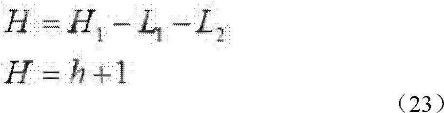
wherein, H is the structural height of the gas path insulator body, and the unit is m; h1Is yang (spleen yang)The height between the pole and the magnetic conduction base is m; l is a radical of an alcohol1Is the length of the air inlet pipe and has the unit of m; l is a radical of an alcohol2Is the length of the air outlet pipe and has the unit of m.
The ceramic cover plate 2 has the same outer diameter as the insulating ceramic ring 203 and is sealed by high temperature ceramic paste.
The insulating ceramic ring 203 is provided with a clamping groove inserted with a metal separation net 208 in an annular gas path; the metal screen 208 is made of stainless steel.
According to the ring-type voltage-dividing gas path insulation structure of the Hall thruster, the gas path is prolonged by increasing the number of rings of the ceramic insulation ring, the number of grading electrodes is increased by increasing the metal separation net, the voltage resistance is remarkably improved, and the expansion capability is strong; meanwhile, the resistance mechanical property is improved by controlling the length-diameter ratio of the structure, and the method has important practical value and application prospect. The annular voltage-dividing air path insulation structure of the Hall thruster changes the axial direction elongation in the prior art to improve the voltage resistance, has small overall envelope, is suitable for being installed inside the Hall thruster, and can fundamentally avoid plasma pollution of the external environment without additionally arranging a protective cover of the voltage-dividing air path insulation structure
Taking a domestic 200W Hall thruster as an example, the anode voltage Vd800V, the operating margin DeltaV is 400V, and the maximum withstand voltage is VmaxIs 1200V; calculating the minimum electrode level number N according to the formula (4)minAnd 8, according to the formula (7), the distance theta between the two metal separation nets is 45 degrees.
When the thruster applied by the invention works, the anode flow qmThe adjustment range is 8-10 sccm, and the viscosity coefficient is 2.1 × 10 for xenon flow at 20 DEG C-5kg·m-1·s-1The gas collision cross section σ is about 1.96 × 10⁻¹⁹m2Mean thermal motion velocity of 280m/s, molecular mass of xenon 2.1810-25kg。
Combining the formulas (8) - (16), the key dimensions of the annular gas path are as follows: r2Is 2.5mm, R35.0mm, h 3 mm. At the moment, the Reynolds number Re of the gas in the annular gas path is about 15.6, the Kenuncai coefficient is 0.0029, and the requirement of viscous flow is met.
Bonding ofEquation (17 to (20), buffer chamber radius R12.0mm, and the Kenuzen coefficient of increase is 0.0037, so that the viscous flow requirement is realized.
Internal diameter R of magnetic conduction base of domestic 200W Hall thrusterinAbout 21mm, high H between the anode and the magnetic conduction base112mm, according to the formulae (22) to (23). The invention discloses a ring type partial pressure gas path insulation structure of a Hall thruster gas supply pipeline, which has the following external dimensions: r is46mm, H5 mm, L1Is 3.5mm, L2Is 3.5mm, is installed in hall thruster magnetic conduction base, realizes thoroughly solving the ceramic gas circuit surface pollution and leads to the insulating inefficacy problem of structure.
Aiming at a ring-type partial pressure gas path insulation structure of a 200W Hall thruster gas supply pipeline, the gas path insulation structure is subjected to a withstand voltage test in a vacuum environment, and the result is an electric insulation structure breakdown voltage test shown in Table 1. The experimental results show that: vacuum degree of 1.0X 10⁻³And when the anode flow is changed within the range of 1.0-12.0 sccm, the withstand voltage value of the gas path insulation structure exceeds 1200V, the purpose of gas path voltage division insulation is met, and the purpose of ring type voltage division gas path insulation design of the Hall thruster is met.
TABLE 1

The existing gas path insulator is an axial partial pressure structure, the basic principle is that the withstand voltage value is improved through multi-stage partial pressure in the axial direction, and when the withstand voltage value is higher, the corresponding stage number is larger, so that the axial structure is overlong, and the mechanical resistance performance is poor; (ii) a Meanwhile, the axial distance is too long, the Hall thruster cannot be installed in the Hall thruster due to space limitation, a protective cover needs to be designed during external installation, the appearance profile is large, and the ceramic outer wall is still polluted to cause breakdown risk under long-term work.
According to the gas path insulator structure, an axial partial pressure structure is changed into an annular partial pressure structure, a gas transmission path is prolonged, and the requirement on voltage resistance is met by arranging different numbers of metal grids; meanwhile, the length-diameter ratio is controlled, and the resistance mechanical property of the gas path insulator is improved; a buffer cavity is designed to homogenize the gas path and reduce the flow rate of the gas path, so that the pressure-resistant reliability is improved; the buffer cavity and the annular gas circuit are arranged in a concentric circle mode, the structure is compact, the axial distance is short, the overall envelope is small, the buffer cavity is arranged inside the thruster in a built-in mode, the thruster is not bombarded by plasma, and the problem of external ceramic pollution is effectively solved. For example, in the above example, the outer diameter of the gas path insulator body is 6mm, the height is 5mm, and the length-diameter ratio is 5: and 6, the pressure resistance is improved, and the mechanical resistance is better.
The above-described embodiments are intended to illustrate the present invention, but not to limit the present invention, and any modifications, equivalents, improvements, etc. made within the spirit of the present invention and the scope of the claims fall within the scope of the present invention.
Claims (9)
1. The utility model provides a hall thruster ring type partial pressure gas circuit insulation system which characterized in that: including intake pipe, insulator body and outlet duct, including cushion chamber, cyclic annular gas circuit and metal separation net in the insulator body, the insulator body is in the columniform cushion chamber that the inner chamber of intercommunication intake pipe set up, the cyclic annular gas circuit in the cushion chamber intercommunication outside, cyclic annular gas circuit is the ring form, the interval sets up a plurality of metals on the cyclic annular gas circuit and separates the net, gaseous get into the cushion chamber through the intake pipe and disturb even deceleration back, let in cyclic annular gas circuit, a plurality of metals that set up through the interval separate the net partial pressure after lead to out through the outlet duct, at the gas circulation in-process, a plurality of metals separate the multiplexing metal electrode that is of net.
2. The ring-type partial pressure gas circuit insulation structure of the Hall thruster of claim 1, which is characterized in that: the insulator body comprises an insulating ceramic ring and a ceramic cover plate, the insulating ceramic ring comprises a cylindrical buffer cavity arranged in the center and an external annular gas circuit, and the buffer cavity and the annular gas circuit are concentrically arranged and have the same height; the buffer cavity is connected with the front end of the annular gas path through the flow guide hole; the annular gas path is a non-closed annular channel separated by a ceramic partition plate, a plurality of stages of metal partition nets are arranged on the annular gas path at equal intervals, and the bottom of the tail end of the annular gas path is provided with a gas outlet hole which is connected with a gas outlet pipe through the gas outlet hole; the ceramic cover plate is a circular cover plate, a round hole is formed in the center of the ceramic cover plate and is connected with the air inlet pipeline through the round hole, and the ceramic cover plate and the insulating ceramic ring have the same outer diameter.
3. The Hall thruster ring type voltage division air path insulation structure of claim 2, wherein: insulating ceramic ring sets up the water conservancy diversion hole between the wall of cyclic annular gas circuit and cushion chamber, and one side of the cyclic annular gas circuit of water conservancy diversion hole intercommunication sets up the baffle, and the baffle sets up the venthole at the opposite side, and the venthole is connected the outlet duct, and gas leads to out from the venthole after letting in cyclic annular gas circuit through the water conservancy diversion hole, forms one-way circulation passageway.
4. The ring-type partial pressure gas circuit insulation structure of the hall thruster of claim 2, which is characterized in that: the insulating ceramic ring is provided with a clamping groove on the annular gas path, and a metal separation net is inserted into the clamping groove; the metal separation net is made of stainless steel.
5. The Hall thruster ring type voltage division air path insulation structure of claim 2, wherein: the insulating ceramic ring is annular, and the insulating ceramic ring and the ceramic cover plate form a disc shape of the insulator body after being sealed.
6. The Hall thruster ring type voltage division air path insulation structure of claim 2, wherein: the insulating ceramic ring and the air outlet pipe are sealed by brazing; the ceramic cover plate and the air inlet pipe are sealed by brazing.
7. The Hall thruster ring type voltage division air path insulation structure of claim 1, wherein: reynolds number Re of gas in annular gas path1The calculation formula is as follows:

wherein q ismIs the gas mass flow rate, and the unit is mg/s; d is cyclic gasThe equivalent diameter of the channel is m, A is the cross-sectional area of the annular gas channel, and m is the unit2Eta is viscosity coefficient of gas in kg · m-1·s-1;
The equivalent diameter D of the annular gas path satisfies the following relationship:

wherein R is2Is the inner diameter of the annular gas path, and the unit is m; r3Is the outer diameter in m; h is height in m;
the cross-sectional area A of the annular gas path satisfies the following relationship:
A=(R3-R2)h (10)
substituting the formula (9) and the formula (10) into the formula (8), further obtaining a calculation formula of the Reynolds number of the gas in the annular gas path as follows:

the calculation formula of the Kenun increase coefficient of the gas in the annular gas path is as follows:

wherein: k isn1The gas is a gas of an annular gas path with a Knoop increasing coefficient; the unit is m, and the average free path of gas in the annular gas path is;
mean free path of gas under the same gas The following formula is satisfied:

wherein σ is a gas collision cross section and has a unit of m2(ii) a n is the gas density in units of units/m3;
The density of the gas in the annular gas path satisfies the following formula:

wherein n is1Is the gas density in units of units/m3; The average thermal movement speed of the gas is given as m/s; m is the gas molecular mass in kg;
the relationship between the pressure in the annular gas path and the gas density is as follows:
P1=n1kT (15)
in the formula, P1Is the gas pressure in Pa; k is Boltzmann constant, and the unit is J/K; t is the gas temperature in K;
according to the ionization performance requirement of gas in a discharge channel of the Hall thruster, the pressure of gas at an inlet of the discharge channel is 100-1000 Pa, and meanwhile, the gas in annular gas needs to meet the viscous flow state, namely:
Re1<1200

100<P1<1000 (16)
combining the formulas (8) to (16) to determine the inner diameter R of the annular gas path2Outer diameter R3And the height h, and the setting of the parameter values of the annular gas circuit realizes that the gas in the gas circuit meets the viscous flow characteristic, thereby ensuring the realization of the grading pressure resistance.
8. The Hall thruster ring type voltage division air path insulation structure of claim 7, wherein: the maximum withstand voltage of the gas path insulation structure is VmaxDesign, setting the anode high voltage as VdAnd if the working margin is delta V, the maximum withstand voltage of the gas path insulator meets the following relation:
Vmax=Vd+ΔV (1)
based on the principle of potential superposition, the high-voltage-resistant parameters are realized through multi-stage voltage division, namely, in a single-connection ventilation circuit, each stage of electrode can resist voltage V by setting N stages of electrodes0Total voltage withstanding parameter V1The following relationship is satisfied:
V1=NV0 (2)
aiming at xenon working medium, in a viscous flow state, when the electrode is made of iron material, the lowest withstand voltage value of two poles is about 150V, therefore, the stage number N of the metal separation net electrode arranged in the annular gas path satisfies the following relation:
150N≥Vmax (3)
the minimum number of stages NminComprises the following steps:

when N is presentminWhen there is remainder, then NminAdding 1; the number N of the metal separation nets is more than or equal to Nmin;
The adjacent metal separation nets need insulation treatment, the minimum distance between the two metal separation nets is d, and the maximum number N of the metal gridsmaxThe following relationship is satisfied:

wherein L is the length of the gas transmission path and has the unit of m; considering point discharge between metal grids, ceramic process and the like, the minimum distance is 2mm, and in the annular gas path, the gas transmission path satisfies the following relation:

wherein, the average radius of the annular gas path is m; according to the analysis, the number N of the metal separation nets is located at NminAnd NmaxIn the meantime.
9. The Hall thruster ring type voltage division air path insulation structure of claim 1, wherein: the gas in the buffer cavity needs to be in a viscous flow state, the gas flowing in from the gas inlet pipe has strong speed and certain non-uniformity, the flow speed of the gas is slowed down through the buffer cavity, the uniformity of the gas is increased, and the Reynolds number calculation formula of the gas in the buffer cavity is as follows:

wherein R is1Is the radius of the buffer cavity, and the unit is m; q. q.smIs the gas mass flow rate, and the unit is mg/s; eta is viscosity coefficient of gas in kg.m-1·s-1;Re2The Reynolds number of the gas in the buffer cavity;
radius of the buffer chamber R1The relationship with the Knoop coefficient of the internal gas is as follows:

wherein, the unit is m, and the average free path of the gas in the buffer cavity is; kn2The gas in the buffer cavity has a Kenun increasing coefficient;
the relationship between the gas density in the buffer chamber and the mass flow of the inlet pipe is as follows:

wherein n is2Is the gas density of the buffer chamber and has unit of per m3;
According to the requirement of viscous flow, the Reynolds number and the Kenuncai coefficient of the gas in the buffer cavity simultaneously meet the following requirements:
Re2<1200

combining the formulas (17) to (20) to further obtain the radius R of the buffer cavity1The following ranges are satisfied:

thereby obtaining the value of the radius of the buffer cavity.
Priority Applications (1)
| Application Number | Priority Date | Filing Date | Title |
|---|---|---|---|
| CN202210380575.5A CN114458564B (en) | 2022-04-12 | 2022-04-12 | Hall thruster ring type partial pressure gas path insulation structure |
Applications Claiming Priority (1)
| Application Number | Priority Date | Filing Date | Title |
|---|---|---|---|
| CN202210380575.5A CN114458564B (en) | 2022-04-12 | 2022-04-12 | Hall thruster ring type partial pressure gas path insulation structure |
Publications (2)
| Publication Number | Publication Date |
|---|---|
| CN114458564A CN114458564A (en) | 2022-05-10 |
| CN114458564B true CN114458564B (en) | 2022-07-12 |
Family
ID=81418611
Family Applications (1)
| Application Number | Title | Priority Date | Filing Date |
|---|---|---|---|
| CN202210380575.5A Active CN114458564B (en) | 2022-04-12 | 2022-04-12 | Hall thruster ring type partial pressure gas path insulation structure |
Country Status (1)
| Country | Link |
|---|---|
| CN (1) | CN114458564B (en) |
Family Cites Families (10)
| Publication number | Priority date | Publication date | Assignee | Title |
|---|---|---|---|---|
| RU2012946C1 (en) * | 1990-06-26 | 1994-05-15 | Опытное конструкторское бюро "Факел" | Plasma cathode-compensator |
| US5646476A (en) * | 1994-12-30 | 1997-07-08 | Electric Propulsion Laboratory, Inc. | Channel ion source |
| US5763989A (en) * | 1995-03-16 | 1998-06-09 | Front Range Fakel, Inc. | Closed drift ion source with improved magnetic field |
| US6448721B2 (en) * | 2000-04-14 | 2002-09-10 | General Plasma Technologies Llc | Cylindrical geometry hall thruster |
| CN105163475A (en) * | 2015-08-03 | 2015-12-16 | 兰州空间技术物理研究所 | Bidirectional gas supplying device for discharging chamber of ion thruster |
| CN105756875B (en) * | 2016-05-12 | 2018-06-19 | 哈尔滨工业大学 | Ionization accelerates integrated space junk plasma propeller |
| CN105889054A (en) * | 2016-06-20 | 2016-08-24 | 无锡鼎茂机械制造有限公司 | Air compressor working environment monitoring system capable of being remotely monitored |
| CN109026580A (en) * | 2018-08-07 | 2018-12-18 | 柳盼 | A kind of delivery method of Hall thruster gaseous propellant |
| CN109779864B (en) * | 2019-03-11 | 2021-10-29 | 哈尔滨工业大学 | A Hall thruster gas supply pipeline insulation structure |
| CN114263581A (en) * | 2021-11-11 | 2022-04-01 | 上海空间推进研究所 | Hollow cathode structure for propellant purification |
-
2022
- 2022-04-12 CN CN202210380575.5A patent/CN114458564B/en active Active
Non-Patent Citations (1)
| Title |
|---|
| 电推力器气路高电压绝缘技术研究;杨福全等;《真空科学与技术学报》;20141215;第34卷(第12期);1290-1293 * |
Also Published As
| Publication number | Publication date |
|---|---|
| CN114458564A (en) | 2022-05-10 |
Similar Documents
| Publication | Publication Date | Title |
|---|---|---|
| CN111385956B (en) | Radio frequency particle source | |
| CN201702023U (en) | Row electrode type low-temperature plasma body discharge industrial waste gas treatment device | |
| CN114458565B (en) | Air path partial pressure insulation method of Hall thruster air supply pipeline and application thereof | |
| CN103247504A (en) | Dual-frequency ion source | |
| CN109555658B (en) | Hall thruster gas distributor structure with porous material partition plate | |
| CN107318213A (en) | The experimental provision of high electric conduction | |
| CN105822516A (en) | Gas flow control method for improving ionization efficiency of Hall thruster | |
| CN114458564B (en) | Hall thruster ring type partial pressure gas path insulation structure | |
| CN114562436A (en) | Sputtering pollution resistant insulation enhanced grid system | |
| CN111852803B (en) | A mixed-effect annular ion thruster based on segmented anodes | |
| CN112628098B (en) | A Hall Accelerator with a Sunken Hollow Inner Magnetic Pole Structure | |
| CN111681936A (en) | A cutting-edge field-shaped negative hydrogen ion source device for a high-energy ion implanter | |
| CN111306024B (en) | A microwave ion propulsion device based on sidewall tangential magnetic field | |
| CN218763868U (en) | Clean room system for semiconductor manufacturing and semiconductor manufacturing system | |
| JPH01501353A (en) | dynamic electron emission device | |
| CN108953088A (en) | A kind of novel hall thruster | |
| CN115822904A (en) | Microwave cathode ion thruster | |
| CN116075030A (en) | A guide net cover for ion fan | |
| CN114007322A (en) | Neutron tube structure with magnetic anode tube penning ion source led out in two directions | |
| CN102978589A (en) | PECVD (plasma enhanced chemical vapor deposition) spray electrode | |
| CN111681937A (en) | A cold cathode Penning ion source device for high energy ion implanter | |
| CN110868790A (en) | Negative hydrogen ion extraction device | |
| CN201229916Y (en) | End-window type ultra-soft X ray tube | |
| CN111710580B (en) | Ion source electric field structure and ion source device | |
| CN114776547A (en) | A fuel-free satellite propulsion device and propulsion method |
Legal Events
| Date | Code | Title | Description |
|---|---|---|---|
| PB01 | Publication | ||
| PB01 | Publication | ||
| SE01 | Entry into force of request for substantive examination | ||
| SE01 | Entry into force of request for substantive examination | ||
| GR01 | Patent grant | ||
| GR01 | Patent grant |