CN114455721B - Green treatment robot for lakes and reservoirs - Google Patents
Green treatment robot for lakes and reservoirs Download PDFInfo
- Publication number
- CN114455721B CN114455721B CN202210073196.1A CN202210073196A CN114455721B CN 114455721 B CN114455721 B CN 114455721B CN 202210073196 A CN202210073196 A CN 202210073196A CN 114455721 B CN114455721 B CN 114455721B
- Authority
- CN
- China
- Prior art keywords
- carrier frame
- mixing
- driving source
- monitoring
- module
- Prior art date
- Legal status (The legal status is an assumption and is not a legal conclusion. Google has not performed a legal analysis and makes no representation as to the accuracy of the status listed.)
- Active
Links
Images


Classifications
-
- C—CHEMISTRY; METALLURGY
- C02—TREATMENT OF WATER, WASTE WATER, SEWAGE, OR SLUDGE
- C02F—TREATMENT OF WATER, WASTE WATER, SEWAGE, OR SLUDGE
- C02F3/00—Biological treatment of water, waste water, or sewage
- C02F3/34—Biological treatment of water, waste water, or sewage characterised by the microorganisms used
-
- C—CHEMISTRY; METALLURGY
- C02—TREATMENT OF WATER, WASTE WATER, SEWAGE, OR SLUDGE
- C02F—TREATMENT OF WATER, WASTE WATER, SEWAGE, OR SLUDGE
- C02F7/00—Aeration of stretches of water
-
- C—CHEMISTRY; METALLURGY
- C02—TREATMENT OF WATER, WASTE WATER, SEWAGE, OR SLUDGE
- C02F—TREATMENT OF WATER, WASTE WATER, SEWAGE, OR SLUDGE
- C02F2103/00—Nature of the water, waste water, sewage or sludge to be treated
- C02F2103/007—Contaminated open waterways, rivers, lakes or ponds
-
- C—CHEMISTRY; METALLURGY
- C02—TREATMENT OF WATER, WASTE WATER, SEWAGE, OR SLUDGE
- C02F—TREATMENT OF WATER, WASTE WATER, SEWAGE, OR SLUDGE
- C02F2209/00—Controlling or monitoring parameters in water treatment
- C02F2209/16—Total nitrogen (tkN-N)
-
- Y—GENERAL TAGGING OF NEW TECHNOLOGICAL DEVELOPMENTS; GENERAL TAGGING OF CROSS-SECTIONAL TECHNOLOGIES SPANNING OVER SEVERAL SECTIONS OF THE IPC; TECHNICAL SUBJECTS COVERED BY FORMER USPC CROSS-REFERENCE ART COLLECTIONS [XRACs] AND DIGESTS
- Y02—TECHNOLOGIES OR APPLICATIONS FOR MITIGATION OR ADAPTATION AGAINST CLIMATE CHANGE
- Y02W—CLIMATE CHANGE MITIGATION TECHNOLOGIES RELATED TO WASTEWATER TREATMENT OR WASTE MANAGEMENT
- Y02W10/00—Technologies for wastewater treatment
- Y02W10/10—Biological treatment of water, waste water, or sewage
Landscapes
- Life Sciences & Earth Sciences (AREA)
- Hydrology & Water Resources (AREA)
- Engineering & Computer Science (AREA)
- Environmental & Geological Engineering (AREA)
- Water Supply & Treatment (AREA)
- Chemical & Material Sciences (AREA)
- Organic Chemistry (AREA)
- Microbiology (AREA)
- Biodiversity & Conservation Biology (AREA)
- Aeration Devices For Treatment Of Activated Polluted Sludge (AREA)
Abstract
The invention discloses a green treatment robot for lakes and reservoirs, which relates to the field of water quality pollution control of lakes and reservoirs and landscape water bodies and aims to solve the problem of single function of the traditional water body treatment equipment; the monitoring module is electrically connected with a central processing module, the mixing device comprises a mixed driving source, the throwing device comprises a throwing driving source, the monitoring module comprises a monitoring driving source and a position signal sending module, the mixed driving source, the throwing driving source and the monitoring driving source are electrically connected to the central processing module, and the position signal sending module is electrically connected to the central processing module.
Description
Technical Field
The invention relates to the technical field of water quality pollution control of lake reservoirs and landscape water bodies, in particular to a green treatment robot for the lake reservoirs.
Background
At present, lake reservoirs are the most precious fresh water resources which can be directly utilized in the world, wherein the reservoirs gradually become the main water supply source of most cities, and the importance of water source reservoirs is highlighted day by day. At present, the problem of water eutrophication faced by lake reservoirs is very prominent, and the deterioration of the water quality of the lake reservoirs directly affects the sustainable utilization of urban water resources, and more seriously threatens the water supply safety of cities. The lake reservoir with larger water depth is easy to generate the phenomenon of water density stratification caused by severe vertical temperature change, the surface water body which is easy to disturb and mix is lack of exchange with the relatively stable bottom water body, after the water density stratification, because the upper and lower layers of water bodies are relatively static and lack of material and energy exchange, the lower layer of water body can not be supplemented with oxygen, the dissolved oxygen is gradually reduced, the anaerobic condition can cause the dissolution and release of organic matters, nitrogen, phosphorus, iron and manganese in bottom mud, the endogenous pollution of the water body is caused, the chromaticity and odor of the water body are increased, the pH value is reduced, the water quality is deteriorated, algae are propagated in large quantities, and the like, and the eutrophication process of the water body is directly accelerated.
The existing water quality treatment of lakes and reservoirs is that a floating carrier frame is arranged on the lake, and then a planting basket for planting aquatic plants is arranged on the carrier frame.
The above prior art solutions have the following drawbacks: but the water pollutant in the lake reservoir water is of a great variety, and the pollutant in the water is handled to the fixed bin on the aquatic plant chinampa in the planting basket alone, and the treatment mode is single, and the effect is limited, and the planting of aquatic plant needs to occupy a large amount of surface of water areas moreover, leads to water pollution to administer not thorough very easily, and aquatic plant management maintenance work volume is big, and this problem is waited to solve urgently.
Disclosure of Invention
The invention aims to provide a green treatment robot for lakes and reservoirs, which has the effect of improving the treatment effect of water bodies in the lakes and reservoirs.
In order to achieve the purpose, the invention provides the following technical scheme:
a lake and reservoir green treatment robot comprises a carrier frame, wherein a plurality of fixed bins for placing microorganism carriers are uniformly arranged on the carrier frame, a mixing device for exchanging upper and lower layers of water bodies into lake water is arranged in the carrier frame, the mixing device comprises a mixing pipe vertically inserted in the water bodies, an oxygenating device for oxygenating the water bodies is arranged in the mixing pipe, a throwing device for throwing microorganism microbial agents into the water bodies is arranged on the upper surface of the carrier frame, and a monitoring module for monitoring water quality parameters is movably arranged on the carrier frame along the vertical direction of the water bodies; the monitoring module is electrically connected with the central processing module, the mixing device comprises a mixed driving source, the throwing device comprises a throwing driving source, the monitoring module comprises a monitoring driving source and a position signal sending module, the mixed driving source, the throwing driving source and the monitoring driving source are all electrically connected with the central processing module, and the position signal sending module is in electric signal connection with the central processing module; the central processing module comprises a data storage module and a signal conversion module.
Through adopting above-mentioned technical scheme, set up the fixed storehouse of placing the microorganism carrier on the carrier frame, mixing arrangement has been set up, set up the input device of oxygenating device and microbial inoculum, set up multiple water quality treatment device on the carrier frame, just can handle multiple water pollutant in the lake reservoir in a flexible way, thereby the effect of lake reservoir water treatment effect has been improved, the last monitoring module that has set up of carrier frame, monitoring module electricity signal connection central processing module, monitoring module gives central processing module through the data transmission of the different degree of depth of monitoring water quality vertical direction, central processing module is through the control mixing driving source, the best operating condition of the control corresponding device of input driving source and monitoring driving source, thereby play the problem of intelligent processing lake reservoir water pollution.
Furthermore, a mixing shell covered on the mixing pipe is arranged on the carrier frame, an overflow hole is formed in the top wall of the mixing shell, a mixing flow channel is formed between the side wall of the mixing shell and the outer side wall of the mixing pipe, and the mixing driving source is arranged on the top wall of the mixing shell; the hybrid drive source is including fixing the hybrid motor on the outer top wall of hybrid case, hybrid motor rotates and is provided with the dwang that stretches into the hybrid tube, the one end that hybrid motor was kept away from to the dwang is provided with stirring vane.
By adopting the technical scheme, when the temperature difference between the upper and lower layers of water bodies in the lake reservoir is more than 1 ℃ and the dissolved oxygen content in the lower layer of water body is lower than 2mg/L, the central control module can control the mixing driving source to work, at the moment, the stirring blades can rotate in the mixing barrel, so that the water at the bottom side in the water body comes to the upper layer through the mixing pipe, the relatively static upper and lower layers of water bodies can be quickly mixed, the water temperature difference between the upper and lower water layers can be reduced, and the dissolved oxygen content in the lower layer of water body can be improved; if the temperature difference of the upper and lower layers of water bodies in the lake and reservoir is less than 1 ℃ and the dissolved oxygen concentration of the lower layer of water body is more than 4mg/L, the central control module controls the mixed driving source to stop working. When the temperature difference of the upper and lower water bodies in the lake and reservoir is gradually reduced and the concentration of dissolved oxygen is gradually increased, the central control module can automatically control the motor speed of the hybrid driving source to be gradually reduced.
Further, the mixing tube is divided into upper mixing tube and lower mixing tube along its length direction, the oxygenation device includes the detachable connection venturi between upper mixing tube and lower mixing tube, venturi is including the last straight section of thick bamboo of connecting the upper mixing tube and the lower straight section of thick bamboo of connecting the lower mixing tube, it is less than the choke of last straight section of thick bamboo and lower straight section of thick bamboo to go up the straight section of thick bamboo and be provided with the aperture down between the straight section of thick bamboo, the choke lateral wall is provided with inspiratory intake pipe.
Through adopting above-mentioned technical scheme, because the aperture of going up straight section of thick bamboo and straight section of thick bamboo down all is greater than the choke, rivers from the in-process of straight section of thick bamboo upward of straight section of thick bamboo down, the liquid velocity of flow of choke department is very fast, can produce the negative pressure and make the intake pipe from external intake air, and the air can follow rivers and continue to enter into the rivers of hybrid tube, then rivers in the hybrid tube can take the air reflux in the water to play the effect of injecting oxygen into the water.
Further, put in the device including fixing the storage case on the carrier frame, the one end that the storage case is close to the carrier frame sets up out the feed cylinder, put in the driving source setting in going out the feed cylinder, put in the driving source including putting in the motor, it is provided with the spiral material pushing sheet of wearing to establish in going out the feed cylinder to rotate on the motor to put in, the carrier frame lateral wall is provided with the material device that spills in the feed cylinder that spills out.
By adopting the technical scheme, after the central control unit receives the information of total nitrogen and total phosphorus, the vertical highest total nitrogen and total phosphorus concentration of the water body in the lakes and reservoirs are determined, the set highest threshold value is compared (the specific numerical value is determined by combining each lake reservoir), if the highest total nitrogen and/or total phosphorus are exceeded, the central control module controls the throwing motor to work, the spiral pushing sheet pushes the microbial agent which is in the storage box and has high-efficiency pollutant degradation into the water body through the discharging barrel, the effect of treating lake water is further achieved, and if the total nitrogen and the total phosphorus in each place of the lakes and reservoirs are lower than the set lowest threshold value, the central control module controls the throwing motor to stop working.
Further, spill the material device and establish the material ring board that spills at carrier frame lateral wall including rotating the cover, the carrier frame is gone up to set up and is stretched out the material platform of placing that spills the material ring board, it is provided with the material motor that spills on placing the bench to spill the material, spill material motor electric connection central control module, it is provided with on the material motor to spill and spills the material gear, it is provided with the material rack that spills the material gear to spill the material ring board lateral wall.
By adopting the technical scheme, the microbial agent can only be thrown to a fixed place by only depending on the material pushing cylinder, so that the microbial agent is not uniformly thrown, the treatment effect of the lake reservoir is reduced, the material scattering ring plate is arranged at the discharge port of the material pushing cylinder, when the microbial agent in the material discharging cylinder falls on the material scattering ring plate, as long as the material scattering motor is started, the material scattering motor can drive the material scattering gear to be meshed with the material scattering rack, so that the material scattering ring plate is driven to rotate, when the rotating speed of the microbial agent and the microbial on the material scattering ring plate is higher, the microbial agent can be scattered from the periphery of the material scattering ring plate, the microbial agent is uniformly scattered into the water body in a large area, and the effect of improving the treatment effect of the lake reservoir is further achieved.
Further, monitoring module includes place the platform, place the platform is last to be provided with temperature probe, dissolved oxygen probe, total nitrogen probe, total phosphorus probe and chlorophyll a probe, position signaling module fixes on place the platform, set up the slip track in the vertical aquatic of inserting on the carrier frame, place the platform slides and sets up to slide on the slip track, it is provided with the driving lead screw to rotate on the carrier frame, the driving lead screw sets up along slip track length direction, driving lead screw thread fit is on place the platform, monitoring driving source fixed connection is served at driving lead screw, the monitoring driving source includes the monitoring motor of fixed connection in driving lead screw one end.
Through adopting above-mentioned technical scheme, temperature probe, dissolved oxygen probe, total nitrogen probe, total phosphorus probe and chlorophyll a probe are installed on place the platform, and place the platform reciprocate just can monitor the quality of water data in different water layers, and the place the platform shell that removes on the one hand reduces monitor probe's a large amount of investments and reduces the monitoring cost, and the place the platform that on the other hand removed can improve monitor module's flexibility and precision.
Furthermore, a positioning inclined strut is arranged on one side of the sliding track in the vertical direction, and one end of the positioning inclined strut is fixed on the carrier frame.
Through adopting above-mentioned technical scheme, the location bracing can improve the connection stability of slip track on carrier frame to play the effect that improves slip track operating stability.
Furthermore, the carrier frame is provided with a connecting hole for inserting the sliding track, one end of the positioning inclined support, which is far away from the carrier frame, is provided with a positioning groove for inserting the sliding track, and the carrier machine is provided with a fixing device for fixing the position of the sliding track.
Through adopting above-mentioned technical scheme, the setting of connecting hole and constant head tank can fix the slip track on the carrier frame, can make things convenient for operating personnel to pull down the slip track from the carrier frame again to play the effect that makes things convenient for operating personnel to overhaul the carrier frame.
Furthermore, a solar cell panel serving as a power supply is arranged on the carrier frame.
Through adopting above-mentioned technical scheme, solar cell panel can supply power for all consumer on the carrier frame to play green's effect.
In conclusion, the beneficial technical effects of the invention are as follows:
1. the carrier frame, the central processing module, the monitoring module, the fixed bin, the throwing device, the mixing device and the oxygenating device are adopted, so that the effect of synergistically improving the treatment effect of the lake water is achieved;
2. the mixing pipe, the mixing motor, the rotating rod, the stirring blades and the oxygenating device are adopted, so that the effects of mixing the upper and lower water bodies and oxygenating the water bodies are achieved, and the excessive growth of algae and the release of endogenous pollutants in bottom mud are effectively controlled;
3. the material storage box, the material discharge barrel, the spiral material pushing sheet and the material scattering device are adopted, so that the effect of improving the feeding range of the microbial agent is achieved.
Drawings
FIG. 1 is a schematic flow chart of the present invention;
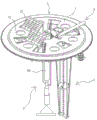
FIG. 2 is a schematic view of the overall structure of the present invention;
FIG. 3 is a schematic diagram of an explosion at the mixing tube in the present invention;
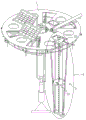
FIG. 4 is a schematic view of a partial cross-sectional structure of a monitoring module according to the present invention;
FIG. 5 is an enlarged view of portion A of FIG. 4;
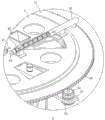
FIG. 6 is a schematic view of a partial cross-sectional structure of a discharge cylinder according to the present invention;
fig. 7 is an enlarged schematic view of a portion B in fig. 6.
In the figure, 1, carrier rack; 11. fixing the bin; 2. a monitoring module; 21. monitoring the driving source; 211. monitoring the motor; 22. a solar panel; 23. placing a platform; 24. a location signal transmitting module; 25. a sliding track; 251. a fixing device; 26. driving the screw rod; 27. positioning an inclined strut; 28. connecting holes; 29. positioning a groove; 3. a mixing device; 31. a mixing tube; 32. a hybrid drive source; 33. a hybrid motor; 34. rotating the rod; 35. agitating the blades; 36. a mixing shell; 37. an overflow aperture; 4. a delivery device; 41. putting a driving source; 42. a material storage box; 43. a discharging barrel; 44. putting a motor; 45. spirally pushing the material sheet; 5. a material spreading device; 51. a material spreading ring plate; 52. a spreading placement table; 54. a material spreading motor; 55. a material spreading gear; 56. a spreading rack; 6. an oxygenating device; 61. an upper mixing pipe; 62. a lower mixing pipe; 63. a venturi tube; 64. an upper straight cylinder; 65. a lower straight cylinder; 66. a throat; 67. an air inlet pipe.
Detailed Description
The present invention will be described in further detail with reference to the accompanying drawings.
Referring to fig. 1, the robot for green treatment of lakes and reservoirs disclosed by the invention comprises a central processing module arranged on a carrier frame 1, wherein the central processing module comprises a data storage module and a signal conversion module, the carrier frame 1 is arranged in a lake water body and floats on the water body, a monitoring module 2 for monitoring the water quality of different water layers in the vertical direction of the water body is arranged on the carrier frame 1, the monitoring module 2 is electrically connected with a central control module, the monitoring module 2 is arranged in a sliding manner along the vertical direction of the water body, a monitoring driving source 21 for driving the monitoring module 2 to move up and down is arranged in the monitoring module, a position signal sending module 24 for sending position signals to the central processing module in real time is also arranged in the monitoring module 2, a mixing device 3 for mixing upper and lower water layers and a throwing device 4 for throwing microorganisms and bactericides into the water body are arranged on the carrier frame 1, the monitoring module 2 continuously monitors the water temperature, the dissolved oxygen content, the total nitrogen content, the total phosphorus content and the chlorophyll a content of the upper and lower water body in the depth direction of the water body, once an index exceeds a safe value, the central control system can intelligently control the mixing driving source 32 and the driving source 41 according to work, the upper and lower layer of water body can be mixed to regulate the temperature and the total oxygen content of the chlorophyll and the total phosphorus content of the microorganism and the total nitrogen content of the chlorophyll a in the water body, once the total nitrogen content of the water body can be regulated by the water body.
Referring to fig. 2 and 3, a plurality of fixed bins 11 for holding microorganism carriers are uniformly distributed on a carrier rack 1, a mixing device 3 is arranged in the middle of the carrier rack 1, the mixing device 3 comprises a mixing tube 31 vertically penetrating into water, a mixing shell 36 is covered on the mixing tube 31, the mixing shell 36 is cylindrically arranged, one end of the mixing shell 36 close to the mixing tube 31 is open, an overflow hole 37 is formed on the top wall of the mixing shell 36, a mixing driving source 32 is fixedly arranged on the outer top wall of the mixing shell 36, the mixing driving source 32 comprises a mixing motor 33 fixed on the mixing shell 36, a rotating rod 34 inserted into the mixing tube 31 is rotatably arranged on the mixing motor 33, and a stirring blade 35 is arranged at one end of the rotating rod 34 extending into the mixing tube 31; mixing tube 31 separates for upper mixing tube 61 and lower mixing tube 62 along its high, be formed with the mixing flow path between mixing shell 36 and the upper mixing tube 61 lateral wall, be provided with the oxygenating device 6 of oxygenating in the water body between upper mixing tube 61 and the lower mixing tube 62, oxygenating device 6 includes venturi 63, venturi 63 includes last straight section of thick bamboo 64 and the lower straight section of thick bamboo 65 of being connected with lower mixing tube 62 with upper mixing tube 61 sealing connection, set up choke 66 between last straight section of thick bamboo 64 and the lower straight section of thick bamboo 65, the aperture of choke 66 is less than last straight section of thick bamboo 64 and lower straight section of thick bamboo 65 aperture, intake pipe 67 will be connected on the choke 66 lateral wall, the one end that choke 66 was kept away from to intake pipe 67 stretches out the water body.
Referring to fig. 4 and 5, a connection hole 28 is formed in the carrier frame 1, the monitoring module 2 includes a monitoring drive source 21, the monitoring drive source 21 includes a sliding rail 25 vertically penetrating through the connection hole 28, the sliding rail 25 includes two vertical round rods, square blocks are arranged at two ends of the sliding rail 25, a drive screw 26 is rotatably penetrated between the two round rods, one end of the drive screw 26 close to the carrier frame 1 is fixedly provided with the monitoring drive source 21, the monitoring drive source 21 includes a monitoring motor 211 fixed on the drive screw 26, one side of the sliding rail 25 in the vertical direction is provided with a positioning inclined strut 27, one end of the positioning inclined strut 27 far away from the carrier frame 1 is provided with a positioning groove 29 for inserting the sliding rail 25, the drive screw 26 is in threaded fit with a circular placing platform 23, the placing platform 23 is sleeved on the two round rods, the placing platform 23 is provided with a water temperature probe, a dissolved oxygen probe, a total nitrogen probe, a total phosphorus probe and a chlorophyll a probe, the position information sending module is fixed on the placing platform 23, a fixing device 251 for fixing the position of the sliding rail 25 in the connection hole 28, the fixing device 251 includes a bolt for fixing the sliding rail 25 on the carrier frame 1 and controlling the monitoring motor to control the maintenance of the integral water body 211, and controlling the monitoring motor to control the maintenance of the monitoring motor by controlling the monitoring motor 211.
Referring to fig. 6 and 7, the feeding device 4 includes a storage box 42 fixed on the carrier frame 1, a discharge barrel 43 is arranged at the bottom end of the storage box 42, a feeding driving source 41 for pushing materials is arranged in the discharge barrel 43, the feeding driving source 41 includes a spiral push sheet 45 rotatably penetrating the discharge barrel 43, a feeding motor 44 is arranged at one end of the spiral push sheet 45, a spreading device 5 for uniformly spreading microbial agents in the discharge barrel 43 is arranged on the outer side wall of the carrier frame 1, the spreading device 5 includes a spreading ring plate 51 rotatably arranged on the outer side wall of the carrier frame 1, a spreading rack 56 is arranged on the outer side wall of the spreading ring plate 51, a spreading placement platform 52 is arranged on the carrier, a spreading motor 54 is fixedly arranged on the placement platform, the spreading motor 54 is also connected with a central control module through a data line, a spreading gear 55 meshing the spreading rack 56 is fixedly arranged on the spreading motor 54, the central control module can automatically control the feeding device 4 in real time according to the concentration condition of water body target pollutants, the microbial agents in the spreading motor 44 and the spreading motor 54 are started, the microbial agents in the storage box 42 can enter the spreading ring plate 43, and then uniformly scan the water body 51 of the microbial agents; the carrier frame 1 is provided with a solar cell panel 22 as a power supply, and the material scattering motor 54, the feeding motor 44, the mixing motor 33 and the monitoring motor 211 are all servo motors, and the rotating speed and the rotating amount of the servo motors can be controlled by a central control module; the central control module is used for electrically connecting the monitoring module 2, the mixing device 3, the oxygenating device 6, the throwing device 4 and the scattering device 5 together through a data line, then automatically executing corresponding operation according to different pollution characteristics and degrees of water bodies, realizing the optimal running state, further reducing the running energy consumption and the wear and maintenance cost of equipment, realizing low carbon, energy conservation and environmental protection, and further reducing the whole equipment investment and the running cost.
The implementation principle of the embodiment is as follows: after receiving the water temperature information, the central processing module controls the rotating speed of a mixing motor 33 in the mixing device 3 to continuously generate circulating water flow to mix the upper and lower layers of water bodies in the lake reservoir; after receiving the information of the total nitrogen amount, the total phosphorus amount and the chlorophyll a amount, the central processing module compares the set highest threshold value (the specific numerical value is determined by combining each lake reservoir) according to the vertical highest total nitrogen amount, the total phosphorus amount and the chlorophyll a amount concentration of the lake reservoir, and if the highest total nitrogen amount, the highest total phosphorus amount and the highest chlorophyll a amount concentration are exceeded, the central processing module starts the feeding device 4 to feed corresponding microbial agents into the lake reservoir for regulating and reducing the total nitrogen amount, the total phosphorus amount and the chlorophyll a amount concentration in the lake reservoir.
The embodiments of the present invention are preferred embodiments of the present invention, and the scope of the present invention is not limited by these embodiments, so: all equivalent changes made according to the structure, shape and principle of the invention are covered by the protection scope of the invention.
Claims (6)
1. The utility model provides a green robot of administering in lake reservoir, includes carrier frame (1), its characterized in that: a plurality of fixed bins (11) for placing microorganism carriers are uniformly arranged on the carrier frame (1), a mixing device (3) for exchanging upper and lower water bodies is arranged in the carrier frame (1), the mixing device (3) comprises a mixing pipe (31) vertically inserted in the water body, an oxygenating device (6) for oxygenating the water body is arranged in the mixing pipe (31), a throwing device (4) for throwing microorganism bacterium agents into the water body is arranged on the upper surface of the carrier frame (1), and a monitoring module (2) for monitoring water quality parameters is movably arranged on the carrier frame (1) along the vertical direction of the water body;
the monitoring module (2) is electrically connected with the central processing module, the mixing device (3) comprises a mixed driving source (32), the throwing device (4) comprises a throwing driving source (41), the monitoring module (2) comprises a monitoring driving source (21) and a position signal sending module (24), the mixed driving source (32), the throwing driving source (41) and the monitoring driving source (21) are all electrically connected with the central processing module, and the position signal sending module (24) is electrically connected with the central processing module;
the central processing module comprises a data storage module and a signal conversion module;
the feeding device (4) comprises a storage box (42) fixed on the carrier frame (1), one end, close to the carrier frame (1), of the storage box (42) is provided with a discharge barrel (43), the feeding driving source (41) is arranged in the discharge barrel (43), the feeding driving source (41) comprises a feeding motor (44), a spiral material pushing sheet (45) penetrating the discharge barrel (43) is rotatably arranged on the feeding motor (44), and a material scattering device (5) for scattering microbial agents in the discharge barrel (43) is arranged on the outer side wall of the carrier frame (1);
the material scattering device (5) comprises a material scattering ring plate (51) which is rotatably sleeved on the outer side wall of the carrier frame (1), a material scattering placing table (52) extending out of the material scattering ring plate (51) is arranged on the carrier frame (1), a material scattering motor (54) is arranged on the material scattering placing table (52), the material scattering motor (54) is electrically connected with a central control module, a material scattering gear (55) is arranged on the material scattering motor (54), and a material scattering rack (56) meshed with the material scattering gear (55) is arranged on the outer side wall of the material scattering ring plate (51);
monitoring module (2) includes place the platform (23), be provided with temperature probe, dissolved oxygen probe, total nitrogen probe, total phosphorus probe and chlorophyll a probe on place the platform (23), position signaling module (24) are fixed on place the platform (23), set up vertical slip track (25) of inserting in the water body on carrier frame (1), place the platform (23) slide and set up on slip track (25), it is provided with drive lead screw (26) to rotate on carrier frame (1), drive lead screw (26) set up along slip track (25) length direction, drive lead screw (26) screw-thread fit is on place the platform (23), monitoring drive source (21) fixed connection is served at drive lead screw (26), monitoring drive source (21) includes monitoring motor (211) of fixed connection in drive lead screw (26) one end.
2. The lake and reservoir green treatment robot of claim 1, wherein: a mixing shell (36) covered on the mixing pipe (31) is arranged on the carrier frame (1), an overflow hole (37) is formed in the top wall of the mixing shell (36), a mixing flow channel is formed between the side wall of the mixing shell (36) and the outer side wall of the mixing pipe (31), and the mixing driving source (32) is arranged on the outer top wall of the mixing shell (36);
mix driving source (32) including fixing hybrid motor (33) on mixing shell (36) outer parietal, it is provided with dwang (34) that stretch into in mixing tube (31) to rotate on hybrid motor (33), the one end that hybrid motor (33) were kept away from in dwang (34) is provided with stirring vane (35).
3. The lake and reservoir green treatment robot of claim 2, which is characterized in that: mixing tube (31) is divided into mixing tube (61) and lower mixing tube (62) along its length direction, oxygenate device (6) including releasable connection at venturi (63) between mixing tube (61) and lower mixing tube (62), venturi (63) including last straight section of thick bamboo (64) of connecting mixing tube (61) and lower straight section of thick bamboo (65) of connecting lower mixing tube (62), it is less than throat (66) of last straight section of thick bamboo (64) and lower straight section of thick bamboo (65) to be provided with the aperture between straight section of thick bamboo (64) and lower straight section of thick bamboo (65) to go up, throat (66) lateral wall is provided with inspiratory air intake pipe (67).
4. The lake and reservoir green treatment robot of claim 3, wherein: one side along the vertical direction of slip track (25) sets up location bracing (27), the one end of location bracing (27) is fixed on carrier frame (1).
5. The lake and reservoir green treatment robot of claim 4, wherein: the carrier frame (1) is provided with a connecting hole (28) for inserting the sliding track (25), one end of the positioning inclined support (27) far away from the carrier frame (1) is provided with a positioning groove (29) for inserting the sliding track (25), and the carrier frame (1) is provided with a fixing device (251) for fixing the position of the sliding track (25).
6. The lake and reservoir green treatment robot of claim 5, which is characterized in that: the carrier frame (1) is provided with a solar cell panel (22) serving as a power supply.
Priority Applications (1)
| Application Number | Priority Date | Filing Date | Title |
|---|---|---|---|
| CN202210073196.1A CN114455721B (en) | 2022-01-21 | 2022-01-21 | Green treatment robot for lakes and reservoirs |
Applications Claiming Priority (1)
| Application Number | Priority Date | Filing Date | Title |
|---|---|---|---|
| CN202210073196.1A CN114455721B (en) | 2022-01-21 | 2022-01-21 | Green treatment robot for lakes and reservoirs |
Publications (2)
| Publication Number | Publication Date |
|---|---|
| CN114455721A CN114455721A (en) | 2022-05-10 |
| CN114455721B true CN114455721B (en) | 2023-03-31 |
Family
ID=81410882
Family Applications (1)
| Application Number | Title | Priority Date | Filing Date |
|---|---|---|---|
| CN202210073196.1A Active CN114455721B (en) | 2022-01-21 | 2022-01-21 | Green treatment robot for lakes and reservoirs |
Country Status (1)
| Country | Link |
|---|---|
| CN (1) | CN114455721B (en) |
Citations (5)
| Publication number | Priority date | Publication date | Assignee | Title |
|---|---|---|---|---|
| JP3022958U (en) * | 1995-09-21 | 1996-04-02 | 薮塚建材興業株式会社 | Medium water storage tank |
| CN103755046A (en) * | 2014-01-07 | 2014-04-30 | 西安建筑科技大学 | In-situ mechanical mixing nitrogen-supply integrated lake reservoir water quality improving device |
| CN111296345A (en) * | 2020-04-07 | 2020-06-19 | 南京工业职业技术学院 | Medicine is spilled and feeds in pond and eat all-in-one |
| CN111646568A (en) * | 2020-06-09 | 2020-09-11 | 长江水利委员会长江科学院 | Mobile carbon fiber biological membrane purification system and method for lake and reservoir water body in-situ treatment |
| CN113917882A (en) * | 2021-12-14 | 2022-01-11 | 南京扬水源环境科技有限公司 | Automatic transfer system of lake and reservoir treatment robot |
-
2022
- 2022-01-21 CN CN202210073196.1A patent/CN114455721B/en active Active
Patent Citations (5)
| Publication number | Priority date | Publication date | Assignee | Title |
|---|---|---|---|---|
| JP3022958U (en) * | 1995-09-21 | 1996-04-02 | 薮塚建材興業株式会社 | Medium water storage tank |
| CN103755046A (en) * | 2014-01-07 | 2014-04-30 | 西安建筑科技大学 | In-situ mechanical mixing nitrogen-supply integrated lake reservoir water quality improving device |
| CN111296345A (en) * | 2020-04-07 | 2020-06-19 | 南京工业职业技术学院 | Medicine is spilled and feeds in pond and eat all-in-one |
| CN111646568A (en) * | 2020-06-09 | 2020-09-11 | 长江水利委员会长江科学院 | Mobile carbon fiber biological membrane purification system and method for lake and reservoir water body in-situ treatment |
| CN113917882A (en) * | 2021-12-14 | 2022-01-11 | 南京扬水源环境科技有限公司 | Automatic transfer system of lake and reservoir treatment robot |
Also Published As
| Publication number | Publication date |
|---|---|
| CN114455721A (en) | 2022-05-10 |
Similar Documents
| Publication | Publication Date | Title |
|---|---|---|
| CN206308098U (en) | A kind of solar energy aeration reoxygenation device for sanitary sewage disposal | |
| CN202193662U (en) | Improved annular type anaerobic, anoxic and aerobic oxidation ditch with functions of lifting and flow propelling | |
| CN103204592A (en) | Water body aeration and oxygen-increasing device with low power consumption and high efficiency | |
| CN204939102U (en) | A kind of mobile solar energy plug-flow aerating apparatus for river regulation and maintenance | |
| CN105417743A (en) | Intermittent mechanical mixing-surface layer oxygenation integrated pilot plant test device | |
| CN204511801U (en) | A kind of wind-energy oxygen-increasing machine | |
| CN114455721B (en) | Green treatment robot for lakes and reservoirs | |
| CN102219312A (en) | Layer disintegrating type circulating aeration technology | |
| CN201376922Y (en) | Photovoltaic water purification device | |
| CN216947026U (en) | Anaerobic sulfate reducing bacteria culture device | |
| CN203269664U (en) | Water aeration oxygenation device with low power consumption and high efficiency | |
| CN113754073B (en) | Microorganism carrier solidification generator | |
| CN205152001U (en) | Drop linkage rotating biological disk | |
| CN211832439U (en) | Circulation subregion layering purifies breed aquatics pond | |
| CN201343454Y (en) | Water body restoration device utilizing solar energy | |
| CN209481307U (en) | A kind of device improving water circulation situation | |
| CN208732744U (en) | A kind of biological treatment reactor for river regulation | |
| CN107739100B (en) | Mixed oxygenation-artificial floating island integrated water quality restoration device | |
| CN218116376U (en) | Electric ship for blue algae treatment | |
| CN218860445U (en) | Novel oxygenation pond for river regulation | |
| CN213306957U (en) | A oxygenation purifier for pond trades water | |
| CN220926298U (en) | Water reflux device after filtering in filter tank | |
| CN215161403U (en) | Multi-point water inlet energy-saving oxidation ditch sewage treatment system | |
| CN214400171U (en) | Black and odorous water body efficient treatment equipment | |
| CN216997828U (en) | Solar energy multidimension plug flow water purifies except that algae device |
Legal Events
| Date | Code | Title | Description |
|---|---|---|---|
| PB01 | Publication | ||
| PB01 | Publication | ||
| SE01 | Entry into force of request for substantive examination | ||
| SE01 | Entry into force of request for substantive examination | ||
| GR01 | Patent grant | ||
| GR01 | Patent grant |