CN114427720A - Heat exchange coupling system of new energy battery and air source heat pump - Google Patents
Heat exchange coupling system of new energy battery and air source heat pump Download PDFInfo
- Publication number
- CN114427720A CN114427720A CN202210217957.6A CN202210217957A CN114427720A CN 114427720 A CN114427720 A CN 114427720A CN 202210217957 A CN202210217957 A CN 202210217957A CN 114427720 A CN114427720 A CN 114427720A
- Authority
- CN
- China
- Prior art keywords
- new energy
- energy battery
- heat exchanger
- battery pack
- heat
- Prior art date
- Legal status (The legal status is an assumption and is not a legal conclusion. Google has not performed a legal analysis and makes no representation as to the accuracy of the status listed.)
- Pending
Links
Images


Classifications
-
- F—MECHANICAL ENGINEERING; LIGHTING; HEATING; WEAPONS; BLASTING
- F24—HEATING; RANGES; VENTILATING
- F24F—AIR-CONDITIONING; AIR-HUMIDIFICATION; VENTILATION; USE OF AIR CURRENTS FOR SCREENING
- F24F5/00—Air-conditioning systems or apparatus not covered by F24F1/00 or F24F3/00, e.g. using solar heat or combined with household units such as an oven or water heater
- F24F5/0007—Air-conditioning systems or apparatus not covered by F24F1/00 or F24F3/00, e.g. using solar heat or combined with household units such as an oven or water heater cooling apparatus specially adapted for use in air-conditioning
- F24F5/001—Compression cycle type
-
- F—MECHANICAL ENGINEERING; LIGHTING; HEATING; WEAPONS; BLASTING
- F24—HEATING; RANGES; VENTILATING
- F24F—AIR-CONDITIONING; AIR-HUMIDIFICATION; VENTILATION; USE OF AIR CURRENTS FOR SCREENING
- F24F1/00—Room units for air-conditioning, e.g. separate or self-contained units or units receiving primary air from a central station
- F24F1/0003—Room units for air-conditioning, e.g. separate or self-contained units or units receiving primary air from a central station characterised by a split arrangement, wherein parts of the air-conditioning system, e.g. evaporator and condenser, are in separately located units
-
- F—MECHANICAL ENGINEERING; LIGHTING; HEATING; WEAPONS; BLASTING
- F24—HEATING; RANGES; VENTILATING
- F24F—AIR-CONDITIONING; AIR-HUMIDIFICATION; VENTILATION; USE OF AIR CURRENTS FOR SCREENING
- F24F13/00—Details common to, or for air-conditioning, air-humidification, ventilation or use of air currents for screening
- F24F13/30—Arrangement or mounting of heat-exchangers
-
- H—ELECTRICITY
- H01—ELECTRIC ELEMENTS
- H01M—PROCESSES OR MEANS, e.g. BATTERIES, FOR THE DIRECT CONVERSION OF CHEMICAL ENERGY INTO ELECTRICAL ENERGY
- H01M10/00—Secondary cells; Manufacture thereof
- H01M10/60—Heating or cooling; Temperature control
- H01M10/61—Types of temperature control
- H01M10/613—Cooling or keeping cold
-
- H—ELECTRICITY
- H01—ELECTRIC ELEMENTS
- H01M—PROCESSES OR MEANS, e.g. BATTERIES, FOR THE DIRECT CONVERSION OF CHEMICAL ENERGY INTO ELECTRICAL ENERGY
- H01M10/00—Secondary cells; Manufacture thereof
- H01M10/60—Heating or cooling; Temperature control
- H01M10/62—Heating or cooling; Temperature control specially adapted for specific applications
- H01M10/627—Stationary installations, e.g. power plant buffering or backup power supplies
-
- H—ELECTRICITY
- H01—ELECTRIC ELEMENTS
- H01M—PROCESSES OR MEANS, e.g. BATTERIES, FOR THE DIRECT CONVERSION OF CHEMICAL ENERGY INTO ELECTRICAL ENERGY
- H01M10/00—Secondary cells; Manufacture thereof
- H01M10/60—Heating or cooling; Temperature control
- H01M10/65—Means for temperature control structurally associated with the cells
- H01M10/655—Solid structures for heat exchange or heat conduction
- H01M10/6556—Solid parts with flow channel passages or pipes for heat exchange
-
- H—ELECTRICITY
- H01—ELECTRIC ELEMENTS
- H01M—PROCESSES OR MEANS, e.g. BATTERIES, FOR THE DIRECT CONVERSION OF CHEMICAL ENERGY INTO ELECTRICAL ENERGY
- H01M10/00—Secondary cells; Manufacture thereof
- H01M10/60—Heating or cooling; Temperature control
- H01M10/65—Means for temperature control structurally associated with the cells
- H01M10/656—Means for temperature control structurally associated with the cells characterised by the type of heat-exchange fluid
- H01M10/6561—Gases
-
- H—ELECTRICITY
- H01—ELECTRIC ELEMENTS
- H01M—PROCESSES OR MEANS, e.g. BATTERIES, FOR THE DIRECT CONVERSION OF CHEMICAL ENERGY INTO ELECTRICAL ENERGY
- H01M10/00—Secondary cells; Manufacture thereof
- H01M10/60—Heating or cooling; Temperature control
- H01M10/66—Heat-exchange relationships between the cells and other systems, e.g. central heating systems or fuel cells
-
- Y—GENERAL TAGGING OF NEW TECHNOLOGICAL DEVELOPMENTS; GENERAL TAGGING OF CROSS-SECTIONAL TECHNOLOGIES SPANNING OVER SEVERAL SECTIONS OF THE IPC; TECHNICAL SUBJECTS COVERED BY FORMER USPC CROSS-REFERENCE ART COLLECTIONS [XRACs] AND DIGESTS
- Y02—TECHNOLOGIES OR APPLICATIONS FOR MITIGATION OR ADAPTATION AGAINST CLIMATE CHANGE
- Y02B—CLIMATE CHANGE MITIGATION TECHNOLOGIES RELATED TO BUILDINGS, e.g. HOUSING, HOUSE APPLIANCES OR RELATED END-USER APPLICATIONS
- Y02B30/00—Energy efficient heating, ventilation or air conditioning [HVAC]
- Y02B30/52—Heat recovery pumps, i.e. heat pump based systems or units able to transfer the thermal energy from one area of the premises or part of the facilities to a different one, improving the overall efficiency
Abstract
The invention belongs to the technical field of energy storage and energy conservation, and particularly relates to a heat exchange coupling system of a new energy battery and an air source heat pump, which comprises an outdoor heat exchanger, a new energy battery pack, a direct current frequency conversion compressor, a four-way reversing valve, a three-way valve, a throttling mechanism, an indoor heat exchanger and a refrigerant pipeline, wherein the outdoor heat exchanger exchanges heat for heat generated in the charging and discharging process of the new energy battery pack, and the new energy battery pack is electrically connected with the direct current frequency conversion compressor in a switchable manner; the three-way valve is positioned between one port of the four-way reversing valve and the direct-current variable-frequency compressor and comprises I-II channels passing through the new energy battery pack. The heat exchange coupling system of the new energy battery and the air source heat pump emphasizes solving the problems of new energy step utilization, heat management of the energy storage battery by forced circulation of the air source heat pump, defrosting and energy saving of the air source heat pump by partially utilizing heat released by the recycled new energy battery and the like.
Description
Technical Field
The invention relates to the technical field of energy storage and energy conservation, in particular to a heat exchange coupling system of a new energy battery and an air source heat pump.
Background
The new energy battery needs to release a large amount of heat in the charging and discharging process, and needs to be subjected to heat management, so that the charging and discharging efficiency of the battery is prevented from being influenced by overhigh internal temperature of the new energy battery; in addition, the air source heat pump system is widely applied to cooling in summer and heating in winter, but energy is consumed in defrosting the heat pump in order to improve the operation performance of the air source heat pump during heating in winter. Therefore, the invention provides a heat exchange coupling system of a new energy battery and an air source heat pump, and aims to solve the problems of gradient utilization of heat of the new energy battery, heat management of the new energy battery and defrosting and energy saving of the air source heat pump.
Disclosure of Invention
Based on the prior art, the invention provides a heat exchange coupling system of a new energy battery and an air source heat pump.
The invention provides a heat exchange coupling system of a new energy battery and an air source heat pump, which comprises an outdoor heat exchanger, a new energy battery pack, a direct-current variable frequency compressor, a four-way reversing valve, a three-way valve, a throttling mechanism, an indoor heat exchanger and a refrigerant pipeline, and is characterized in that:
the outdoor heat exchanger is used for thermally coupling heat generated in the charging and discharging processes of the new energy battery pack, and the new energy battery pack is electrically connected with the direct-current variable-frequency compressor in a switchable manner;
the three-way valve is positioned between one port of the four-way reversing valve and the direct-current variable-frequency compressor and comprises an I-II channel passing through the new energy battery pack and an I-III channel not passing through the new energy battery pack;
in the heating state, the refrigerant of the outdoor heat exchanger absorbs heat energy released by air and the new energy battery pack or air heat energy, is compressed by the compressor after passing through the four-way reversing valve, enters the indoor heat exchanger for releasing heat, enters the throttling mechanism through the four-way reversing valve, and returns to the outdoor heat exchanger for circulating heating;
in a refrigerating state, the refrigerant of the indoor heat exchanger absorbs indoor heat, then enters the four-way reversing valve, the compressor, the outdoor heat exchanger to release heat, enters the throttling mechanism through the four-way reversing valve, and then returns to the indoor heat exchanger to perform circulating refrigeration.
Preferably, the electric core groups in the new energy battery pack are fixed on four vertical surfaces inside the outdoor heat exchanger in an up-down interval mode, and each electric core group is provided with a plurality of electric cores;
air flow channels are arranged between every two adjacent electric core groups and between the electric cores of the same electric core group;
when the heating state is achieved, the outdoor heat exchanger absorbs the discharged heat of the charge and discharge of the battery cell through the air channel by the fan, and the heat is thermally coupled through the fin type heat exchanger inside the outdoor heat exchanger.
Preferably, any two electric cores of each group of electric cores are connected through an aluminum foil wrapped outside the side surface, copper pipes are arranged on the end surfaces of the aluminum foils, and after the copper pipes are transversely distributed, the two ends of the copper pipes are communicated through the same pipeline and are positioned on the I-II channel;
and when the battery pack is in a refrigerating state, the refrigerants on the I-II channels are communicated with the copper pipes to absorb heat generated in the charging and discharging processes of the new energy battery pack transmitted through the aluminum foil.
By the technical scheme, the thickness of the aluminum foil is less than 0.20mm, and the cross section of the rolled aluminum product is rectangular and uniform. Including capacitor aluminum foil, hydrophilic aluminum foil, composite aluminum foil, etc., and has excellent heat conducting effect. Can realize radiating effect through air runner and air admission passageway to every electric core in the new forms of energy group battery.
Through above-mentioned technical scheme, can give new forms of energy group battery initiative radiating effect through the fan, can use current control by temperature change technique to carry out temperature control with the fan and open and stop to realize energy-saving radiating effect. Copper pipes are distributed at two ends of the battery cell to achieve various heat dissipation effects in the directions of the two ends of the battery cell.
The beneficial effects of the invention are as follows:
1. the air source heat pump operates in a heating mode, a power supply for driving the air source heat pump is a power supply of a power grid or a power supply stored in a new energy battery, and the new energy battery pack is set to be an evaporator in a heat pump system in the charging and discharging processes, so that the energy storage new energy battery and a heat management heat exchanger are used as heat to be released in the charging and discharging processes, the released heat can be absorbed by the energy storage new energy battery and the heat management heat exchanger in the air source heat pump, the frosting probability of the heat exchanger is greatly reduced, and the defrosting problem of the air source heat pump can be solved; after the heat emitted by the new energy battery pack is taken away, the temperature of the new energy battery pack is also controlled, so that the charge and discharge efficiency of the new energy battery is improved.
2. The air source heat pump is arranged to operate in a refrigeration mode, a power supply of the air source heat pump is driven to be a power supply of a power grid or a power supply stored in a new energy battery, the new energy battery and the heat management heat exchanger are arranged to be condensers in a heat pump system in the charging and discharging process of the new energy battery pack, the new energy battery pack emits heat in the charging and discharging process, the emitted heat can be taken away by air around the new energy battery pack, and the temperature of the new energy battery pack is controlled after the heat is taken away, so that the charging and discharging efficiency of the new energy battery pack is improved; if the heat that the peripheral air of new forms of energy group battery was taken away is not enough to reduce the temperature of new forms of energy battery electric core, and then switches on through the I-II passageway of control three-way valve, makes the low pressure refrigerant get into the copper pipe inside in the installation casing, further cools down new forms of energy battery electric core through the aluminium foil of new forms of energy battery electricity core outside parcel to improve the charge-discharge efficiency of new forms of energy battery.
Drawings
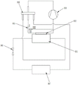
Fig. 1 is a schematic diagram of a heat exchange coupling system of a new energy battery and an air source heat pump according to the present invention;
fig. 2 is a perspective view of an outdoor heat exchanger structure of a heat exchange coupling system of a new energy battery and an air source heat pump according to the present invention;
fig. 3 is a front sectional view of an outdoor heat exchanger structure of a heat exchange coupling system of a new energy battery and an air source heat pump according to the present invention;
fig. 4 is a sectional view 1-1 in fig. 3 of a heat exchange coupling system of a new energy battery and an air source heat pump according to the present invention;
fig. 5 is a schematic diagram of a working mode of a heat exchange coupling system of a new energy battery and an air source heat pump according to the present invention;
fig. 6 is a schematic diagram of a second working mode of the heat exchange coupling system of the new energy battery and the air source heat pump provided by the invention;
fig. 7 is a three-principle diagram of the working mode of the heat exchange coupling system of the new energy battery and the air source heat pump provided by the invention;
fig. 8 is a four-principle diagram of the working mode of the heat exchange coupling system of the new energy battery and the air source heat pump provided by the invention.
In the figure: 01. an outdoor heat exchanger; 011. aluminum foil; 012. an air flow passage; 013. a copper pipe; 02. a new energy battery pack; 03. a direct current variable frequency compressor; 04. a four-way reversing valve; 05. a three-way valve; 06. a throttle mechanism; 07. an indoor heat exchanger.
Detailed Description
The technical solutions in the embodiments of the present invention will be clearly and completely described below with reference to the drawings in the embodiments of the present invention, and it is obvious that the described embodiments are only a part of the embodiments of the present invention, and not all of the embodiments.
Referring to fig. 1 to 8, a heat exchange coupling system of a new energy battery and an air source heat pump includes the air source heat pump, the air source heat pump includes an outdoor heat exchanger 01 for exchanging heat with a new energy battery pack 02, and the new energy battery pack 02 includes, but is not limited to, a new energy battery pack as long as the new energy battery can be charged and discharged.
Further, the electric cells in the new energy battery pack 02 are fixed on four vertical surfaces inside the outdoor heat exchanger 01 at equal intervals, but are not all located on all the inner space of the outer heat exchanger 01. Each electric core group is provided with a plurality of electric cores; air flow channels (012) are arranged between two adjacent electric cores of the electric core group and the electric core of the same electric core group; the air flow passage 012 realizes heat circulation around the upper, lower, left, right, and front of the electric core in the new energy battery pack 02, and can realize a heat dissipation effect on each electric core in the new energy battery pack 02 through the air flow passage 012.
The fan of the outdoor heat exchanger 01 absorbs the heat released by the charging and discharging of the battery cell through the air channel 012, and the heat is thermally coupled through the fin heat exchanger inside the outdoor heat exchanger 01. Can give new forms of energy group battery 02 initiative radiating effect through the fan, can use current control by temperature change technique to carry out temperature control with the fan and open and stop to realize energy-saving radiating effect.
Further, the outer surface of each battery cell in the new energy battery pack 02 is also fixedly wrapped with an aluminum foil 011. The aluminum foil 011 is a uniformly rolled aluminum product with the thickness less than 0.20mm and the cross section of the aluminum foil being rectangular. Including capacitor aluminum foil, hydrophilic aluminum foil, composite aluminum foil and the like, and has good heat conduction effect. The end face of the aluminum foil 011 is provided with a plurality of copper pipes 013, and after the copper pipes 013 are transversely distributed, the two ends of each copper pipe are communicated through the same pipeline. Utilize copper pipe 013 to distribute in the both ends department of electric core, combine the aluminium foil in order to realize the ascending radiating effect in electric core both ends direction.
Furthermore, the inlet end of the copper pipe 013 is communicated with a port II of the three-way valve 05, low-pressure refrigerant is introduced into the copper pipe 013 to realize refrigeration after the I-II channels in the three-way valve 05 are controlled to be communicated, and the I-III channels in the three-way valve 05 are communicated when the refrigeration is not performed. The copper pipe 013 is filled with a low-pressure refrigerant to realize the refrigeration type heat dissipation effect.
And the outdoor heat exchanger 01 is communicated with a four-way reversing valve 04, is subjected to primary reversing, and then is introduced into the direct-current variable-frequency compressor 03.
The direct-current variable-frequency compressor 03 is communicated with a three-way valve 05, then communicated with the four-way reversing valve 04 to realize secondary reversing, and finally introduced into the indoor heat exchanger 07;
the indoor heat exchanger 07 is communicated with the outdoor heat exchanger 01 through a throttling mechanism 06, and finally defrosting action is achieved on one or two of the outdoor heat exchanger 01 and the indoor heat exchanger 07.
Further, the new energy battery pack 02 is electrically connected with the direct-current variable-frequency compressor 03 to supply power. One of two power supply modes of alternating current and direct current can be realized according to the actual power supply mode of the direct current variable frequency compressor 03, so that the application range is increased.
Further, the air source heat pump is powered by a double power supply: when the commercial power is at the power supply valley peak, the commercial power charges the new energy battery pack 02 in the air source heat pump and supplies power to other electrical appliance elements.
When the commercial power is at the peak of the power supply, the new energy battery pack 02 discharges to supply power to other electrical appliance elements in the air source heat pump.
The air source heat pump is controlled by the aid of the power consumption peak and valley of the commercial power, so that the air source heat pump has the maximum energy-saving and environment-friendly effects while being kept in a working state all the time.
Further, when the heat generated during charging and discharging of the new energy battery pack 02 reaches a preset temperature, the channels i-ii in the three-way valve 05 are conducted, a low-pressure refrigerant is introduced into the copper pipe 013 to achieve refrigeration, and finally the low-pressure refrigerant in the copper pipe 013 cools the battery cell in the new energy battery pack 02 through the aluminum foil 011. The refrigeration type heat dissipation effect is realized by using the low-pressure refrigerant, and meanwhile, the release control of the low-pressure refrigerant can be controlled by using the existing temperature control technology, so that the refrigeration type heat dissipation device has the effects of energy conservation and environmental protection.
Further, the throttle mechanism 06 includes, but is not limited to, an electromagnetic throttle valve. The electromagnetic throttle valve can be conveniently electrically controlled, and has the effect of convenient control.
On one hand, the air source heat pump is arranged to operate in a heating mode, a power supply for driving the air source heat pump is a power supply of a power grid or a power supply for storing a new energy battery, the new energy battery pack is arranged to be an evaporator in a heat pump system in the charging and discharging processes, the new energy battery pack emits heat in the charging and discharging processes, the emitted heat can be absorbed by the new energy battery in the air source heat pump and the heat management heat exchanger, the frosting probability of the heat exchanger is greatly reduced, and the defrosting problem of the air source heat pump can be solved; after the heat emitted by the new energy battery pack is taken away, the temperature of the new energy battery pack is also controlled, so that the charge and discharge efficiency of the new energy battery is improved.
On the other hand, the air source heat pump is arranged to operate in a refrigeration mode, a power supply for driving the air source heat pump is a power supply of a power grid or a power supply stored in a new energy battery, the new energy battery pack is arranged to enable the energy storage new energy battery and the heat management heat exchanger to be condensers in the heat pump system in the charging and discharging process, the new energy battery pack emits heat in the charging and discharging process, the emitted heat can be taken away by air around the new energy battery pack, the temperature of the new energy battery pack is controlled after the heat is taken away, and therefore the charging and discharging efficiency of the new energy battery pack is improved; if the heat that the peripheral air of new forms of energy group battery was taken away is not enough to reduce the temperature of new forms of energy battery electricity core, and then switches on through the I-II passageway of control three-way valve, makes the low pressure refrigerant get into inside the copper pipe 013 in the installation casing, further cools down new forms of energy battery electricity core through the aluminium foil of new forms of energy battery electricity core outside parcel to improve new forms of energy battery's charge-discharge efficiency.
The specific application scenarios of the heating mode and the cooling mode described above include the following four operation modes:
firstly, during the winter valley commercial power period, the valley power grid is utilized to supply heat and charge the new energy battery through the air source heat pump.
In the operation mode, on one hand, the air source heat pump operates in the heating mode, and a power supply for driving the air source heat pump is a power supply of a power grid; on the other hand, the new energy battery pack is in a charging mode and charges the new energy battery through a power grid power supply; at the moment, the outdoor heat exchanger 01 with the new energy battery pack 02 has the function of an evaporator in a heat pump system, the indoor heat exchanger 07 has the function of a condenser, the new energy battery pack 02 releases heat during charging, the released heat can be absorbed by the new energy battery pack 02 and the outdoor heat exchanger 01 in the air source heat pump, the frosting probability of the outdoor heat exchanger 01 is greatly reduced, and the problem of defrosting of the air source heat pump can be solved; after the heat emitted by the new energy battery pack 02 is taken away, the temperature rise of the new energy battery is also controlled, so that the charging efficiency of the new energy battery is improved.
And secondly, during the peak electricity period in winter, driving the air source heat pump to supply heat by using the new energy battery.
In the operation mode, the air source heat pump operates in the heating mode, a power supply for driving the air source heat pump is a power supply stored in the new energy battery pack 02, and the new energy battery pack 02 is in the discharging mode. At this time, the outdoor heat exchanger 01 with the new energy battery pack 02 serves as an evaporator in the heat pump system, and the indoor heat exchanger 07 serves as a condenser. The new energy battery pack 02 emits heat during discharging, the emitted heat can be absorbed by an outdoor heat exchanger 01 with the new energy battery pack 02 in the air source heat pump, the frosting probability of the heat exchanger is greatly reduced, and the defrosting problem of the air source heat pump can be solved; after the heat emitted by the new energy battery is taken away, the temperature rise of the new energy battery is also controlled, so that the discharge efficiency of the new energy battery is improved.
Certainly, in an extreme environment, when the battery pack 02 runs in winter, if the electric core in the new energy battery pack 02 needs to be heated, the three-way valve 05 is controlled to conduct the channels i to ii in the three-way valve 05, the refrigerant enters the copper pipe 013 of the refrigerant flow channel, and the new energy battery pack 02 is heated through the aluminum foil 011 wrapped outside the electric core of the new energy battery pack 02, so that the battery is protected.
And thirdly, during the low ebb electricity period in summer, the power grid in the low ebb is used for transmitting electricity, and the new energy battery is refrigerated and charged through the air source heat pump.
In the operation mode, on one hand, the air source heat pump operates in the refrigeration mode, and a power supply for driving the air source heat pump is a power supply of a power grid; on the other hand, the new energy battery pack 02 is in a charging mode, and the battery cell in the new energy battery pack 02 is charged through the power supply of the power grid; at the moment, the outdoor heat exchanger 01 with the new energy battery pack 02 is a condenser in a heat pump system, the indoor heat exchanger 07 is used as an evaporator, the new energy battery pack 02 emits heat during charging, the heat emitted by the new energy battery pack 02 is taken away by air around the new energy battery, and the temperature rise of the new energy battery pack 02 is controlled after the heat is taken away, so that the charging efficiency of the new energy battery is improved; if the heat taken away by the air around the electric core in the new energy battery pack 02 is not enough to reduce the temperature rise of the new energy battery pack 02, the I-II channels in the three-way valve 05 are conducted by controlling the three-way valve 05, the low-pressure refrigerant enters the copper pipe 013 of the refrigerant flow channel, and the new energy battery pack 02 is further cooled by the aluminum foil 011 wrapped outside the electric core of the new energy battery pack 02, so that the charging efficiency of the new energy battery is improved.
And fourthly, driving an air source heat pump to perform a refrigeration mode by using the new energy battery during the summer peak electricity period.
In the operation mode, the air source heat pump operates in the cooling mode, the power supply for driving the air source heat pump is the power supply stored in the new energy battery pack 02, and the new energy battery pack 02 is in the discharging mode. At the moment, the outdoor heat exchanger 01 with the new energy battery pack 02 is a condenser in the heat pump system, the indoor heat exchanger 07 serves as an evaporator, the new energy battery pack 02 emits heat during charging, the heat emitted by the new energy battery pack 02 is taken away by air around the new energy battery, and the temperature rise of the new energy battery pack 02 is controlled after the heat is taken away, so that the charging efficiency of the new energy battery is improved; if the heat taken away by the air around the electric core in the new energy battery pack 02 is not enough to reduce the temperature rise of the new energy battery pack 02, the I-II channels in the three-way valve 05 are conducted by controlling the three-way valve 05, the low-pressure refrigerant enters the copper pipe 013 of the refrigerant flow channel, and the new energy battery pack 02 is further cooled by the aluminum foil 011 wrapped outside the electric core of the new energy battery pack 02, so that the charging efficiency of the new energy battery is improved.
It should be noted that in the present invention, the conduction of the i-ii channels does not mean that the i-iii channels are turned off, and the i-ii channels may be independently conducted or the i-ii channels and the i-iii channels may be simultaneously conducted as long as the thermal management of the new energy battery pack can be implemented.
The above description is only for the preferred embodiment of the present invention, but the scope of the present invention is not limited thereto, and any person skilled in the art should be considered to be within the technical scope of the present invention, and the technical solutions and the inventive concepts thereof according to the present invention should be equivalent or changed within the scope of the present invention.
Claims (3)
1. The utility model provides a new forms of energy battery and air source heat pump's heat transfer coupled system, includes outdoor heat exchanger (01), new forms of energy group battery (02), direct current frequency conversion compressor (03), four-way reversing valve (04), three-way valve (05), throttle mechanism (06), indoor heat exchanger (07) and refrigerant pipeline, its characterized in that:
the outdoor heat exchanger (01) is used for thermally coupling heat generated in the charging and discharging processes of the new energy battery pack (02), and the new energy battery pack (02) is electrically connected with the direct-current variable-frequency compressor (03) in a switchable manner;
the three-way valve (05) is positioned between one port of the four-way reversing valve (04) and the direct-current variable-frequency compressor (03), and comprises an I-II channel passing through the new energy battery pack (02) and an I-III channel not passing through the new energy battery pack (02);
in the heating state, the refrigerant of the outdoor heat exchanger (01) absorbs heat energy or air heat energy released by air and the new energy battery pack (02), is compressed by the compressor (03) after passing through the four-way reversing valve (04), enters the indoor heat exchanger (07) for releasing heat, enters the throttling mechanism (06) through the four-way reversing valve (04), and returns to the outdoor heat exchanger (01) for circulating heating;
in a refrigerating state, the refrigerant of the indoor heat exchanger (07) absorbs indoor heat, then enters the four-way reversing valve (04) and the compressor (03), releases heat through the outdoor heat exchanger (07), enters the throttling mechanism (06) through the four-way reversing valve (04), and returns to the indoor heat exchanger (07) for circulating refrigeration.
2. The heat exchange coupling system of the new energy battery and the air source heat pump according to claim 1, characterized in that: the electric core groups in the new energy battery pack (02) are fixed on four vertical surfaces in the outdoor heat exchanger (01) in an up-down interval mode, and each electric core group is provided with a plurality of electric cores;
air flow channels (012) are arranged between two adjacent electric core groups and the electric core of the same electric core group;
when the outdoor heat exchanger (01) is in a heating state, the air flow passes through the fan, the air channel (012) absorbs the heat released by the charge and discharge of the battery cell, and the heat is thermally coupled through the fin type heat exchanger inside the outdoor heat exchanger (01).
3. The heat exchange coupling system of the new energy battery and the air source heat pump according to claim 2, characterized in that: any two electric cores of each group of electric cores are connected through an aluminum foil (011) wrapped outside the side surface, the end surface of the aluminum foil (011) is provided with a copper pipe (013), after the copper pipes (013) are transversely distributed, the two ends of each copper pipe are communicated through the same pipeline and are positioned on the I-II channel;
in a refrigeration state, the refrigerant on the I-II channel is led to the copper pipe (013) to absorb the heat generated in the charging and discharging processes of the new energy battery pack (02) transmitted through the aluminum foil (011).
Priority Applications (1)
| Application Number | Priority Date | Filing Date | Title |
|---|---|---|---|
| CN202210217957.6A CN114427720A (en) | 2022-03-07 | 2022-03-07 | Heat exchange coupling system of new energy battery and air source heat pump |
Applications Claiming Priority (1)
| Application Number | Priority Date | Filing Date | Title |
|---|---|---|---|
| CN202210217957.6A CN114427720A (en) | 2022-03-07 | 2022-03-07 | Heat exchange coupling system of new energy battery and air source heat pump |
Publications (1)
| Publication Number | Publication Date |
|---|---|
| CN114427720A true CN114427720A (en) | 2022-05-03 |
Family
ID=81312815
Family Applications (1)
| Application Number | Title | Priority Date | Filing Date |
|---|---|---|---|
| CN202210217957.6A Pending CN114427720A (en) | 2022-03-07 | 2022-03-07 | Heat exchange coupling system of new energy battery and air source heat pump |
Country Status (1)
| Country | Link |
|---|---|
| CN (1) | CN114427720A (en) |
Citations (9)
| Publication number | Priority date | Publication date | Assignee | Title |
|---|---|---|---|---|
| JP2008173992A (en) * | 2007-01-16 | 2008-07-31 | Toyota Motor Corp | Fuel cell system |
| CN105552474A (en) * | 2016-02-18 | 2016-05-04 | 华南理工大学 | Circular flow air cooling heat radiation device of power batteries |
| CN205930310U (en) * | 2016-05-10 | 2017-02-08 | 比亚迪股份有限公司 | Electric automobile thermal management system and electric automobile |
| CN109686891A (en) * | 2019-01-16 | 2019-04-26 | 郑州比克新能源汽车有限公司 | A kind of liquid integrated battery pack of wind |
| CN109760485A (en) * | 2018-12-29 | 2019-05-17 | 西安交通大学 | It is a kind of with refrigerating/heating/boosting battery packet heat sinking function carbon dioxide system |
| CN111811087A (en) * | 2020-07-20 | 2020-10-23 | 珠海格力电器股份有限公司 | Air conditioner external unit, control method and air conditioner |
| CN112594918A (en) * | 2020-12-14 | 2021-04-02 | 青岛海尔空调器有限总公司 | Air conditioner heat exchange system and control method thereof |
| CN112622567A (en) * | 2020-12-25 | 2021-04-09 | 青岛朗进新能源设备有限公司 | Vehicle-mounted air conditioning system integrating battery cooling function |
| US20220032725A1 (en) * | 2018-10-09 | 2022-02-03 | Sanden Automotive Climate Systems Corporation | Vehicle air conditioning device |
-
2022
- 2022-03-07 CN CN202210217957.6A patent/CN114427720A/en active Pending
Patent Citations (9)
| Publication number | Priority date | Publication date | Assignee | Title |
|---|---|---|---|---|
| JP2008173992A (en) * | 2007-01-16 | 2008-07-31 | Toyota Motor Corp | Fuel cell system |
| CN105552474A (en) * | 2016-02-18 | 2016-05-04 | 华南理工大学 | Circular flow air cooling heat radiation device of power batteries |
| CN205930310U (en) * | 2016-05-10 | 2017-02-08 | 比亚迪股份有限公司 | Electric automobile thermal management system and electric automobile |
| US20220032725A1 (en) * | 2018-10-09 | 2022-02-03 | Sanden Automotive Climate Systems Corporation | Vehicle air conditioning device |
| CN109760485A (en) * | 2018-12-29 | 2019-05-17 | 西安交通大学 | It is a kind of with refrigerating/heating/boosting battery packet heat sinking function carbon dioxide system |
| CN109686891A (en) * | 2019-01-16 | 2019-04-26 | 郑州比克新能源汽车有限公司 | A kind of liquid integrated battery pack of wind |
| CN111811087A (en) * | 2020-07-20 | 2020-10-23 | 珠海格力电器股份有限公司 | Air conditioner external unit, control method and air conditioner |
| CN112594918A (en) * | 2020-12-14 | 2021-04-02 | 青岛海尔空调器有限总公司 | Air conditioner heat exchange system and control method thereof |
| CN112622567A (en) * | 2020-12-25 | 2021-04-09 | 青岛朗进新能源设备有限公司 | Vehicle-mounted air conditioning system integrating battery cooling function |
Similar Documents
| Publication | Publication Date | Title |
|---|---|---|
| CN205194809U (en) | Electric automobile power battery's thermal management system and electric automobile | |
| US20240116327A1 (en) | Electrical vehicle thermal management system and method based on self-circulating gas-liquid phase change cold plate | |
| CN107166601A (en) | A kind of water circulation hot and cold dual control all-in-one | |
| CN102937315A (en) | Refrigeration and cold accumulation system | |
| CN211476360U (en) | Ground source heat pump air conditioning device for energy storage battery container | |
| CN201368551Y (en) | Air conditioner for combining ground source heat pump and ice-storage system | |
| CN208042395U (en) | A kind of new air heat-exchange device based on solar energy power generating semiconductor refrigerating | |
| CN219696549U (en) | Novel thermal management unit of wind power energy storage battery | |
| CN213636112U (en) | Water chilling unit and energy storage system | |
| CN111750418A (en) | Heat pipe type photovoltaic photo-thermal module-heat pump-phase change material coupling system and method | |
| CN108105843B (en) | Liquid heat accumulation cold-storage all-in-one | |
| CN114427720A (en) | Heat exchange coupling system of new energy battery and air source heat pump | |
| CN208042405U (en) | A kind of photovoltaic air-conditioning wall | |
| CN102927721A (en) | Ternary bidirectional phase change energy storage type heat exchanger | |
| CN105333543A (en) | Multifunctional central air-conditioning system and running control method thereof | |
| CN104566726A (en) | Novel household efficient static ice-making and indirect de-icing type cooling air conditioning system | |
| CN204830275U (en) | Multi -functional central air -conditioning system | |
| CN213656920U (en) | Heat pipe type photovoltaic photo-thermal module-heat pump-phase change floor coupling system | |
| CN212961846U (en) | Heat pipe type photovoltaic photo-thermal module-heat pump-phase change material coupling system | |
| CN209763390U (en) | Refrigerating device with dehumidification function | |
| CN208042559U (en) | A kind of high-efficiency air source heat pump device | |
| CN102734878A (en) | High-efficiency dual-temperature air source heat pump assembly dedicated to capillary radiation air-conditioning system | |
| CN207006437U (en) | A kind of water circulation thermostatic control machine | |
| CN111750417A (en) | Heat pipe type photovoltaic photo-thermal module-heat pump-phase change floor coupling system and method | |
| CN111397250A (en) | Heat adjustable heat pipe heating device with R134a as working medium |
Legal Events
| Date | Code | Title | Description |
|---|---|---|---|
| PB01 | Publication | ||
| PB01 | Publication | ||
| SE01 | Entry into force of request for substantive examination | ||
| SE01 | Entry into force of request for substantive examination |