CN114406745A - Automatic quick clamp tooling system for round workpieces - Google Patents
Automatic quick clamp tooling system for round workpieces Download PDFInfo
- Publication number
- CN114406745A CN114406745A CN202111666342.3A CN202111666342A CN114406745A CN 114406745 A CN114406745 A CN 114406745A CN 202111666342 A CN202111666342 A CN 202111666342A CN 114406745 A CN114406745 A CN 114406745A
- Authority
- CN
- China
- Prior art keywords
- fixedly connected
- plates
- square
- sub
- clamping
- Prior art date
- Legal status (The legal status is an assumption and is not a legal conclusion. Google has not performed a legal analysis and makes no representation as to the accuracy of the status listed.)
- Withdrawn
Links
Images


Classifications
-
- B—PERFORMING OPERATIONS; TRANSPORTING
- B23—MACHINE TOOLS; METAL-WORKING NOT OTHERWISE PROVIDED FOR
- B23Q—DETAILS, COMPONENTS, OR ACCESSORIES FOR MACHINE TOOLS, e.g. ARRANGEMENTS FOR COPYING OR CONTROLLING; MACHINE TOOLS IN GENERAL CHARACTERISED BY THE CONSTRUCTION OF PARTICULAR DETAILS OR COMPONENTS; COMBINATIONS OR ASSOCIATIONS OF METAL-WORKING MACHINES, NOT DIRECTED TO A PARTICULAR RESULT
- B23Q3/00—Devices holding, supporting, or positioning work or tools, of a kind normally removable from the machine
- B23Q3/02—Devices holding, supporting, or positioning work or tools, of a kind normally removable from the machine for mounting on a work-table, tool-slide, or analogous part
- B23Q3/06—Work-clamping means
-
- B—PERFORMING OPERATIONS; TRANSPORTING
- B24—GRINDING; POLISHING
- B24B—MACHINES, DEVICES, OR PROCESSES FOR GRINDING OR POLISHING; DRESSING OR CONDITIONING OF ABRADING SURFACES; FEEDING OF GRINDING, POLISHING, OR LAPPING AGENTS
- B24B41/00—Component parts such as frames, beds, carriages, headstocks
- B24B41/06—Work supports, e.g. adjustable steadies
Landscapes
- Engineering & Computer Science (AREA)
- Mechanical Engineering (AREA)
- Jigs For Machine Tools (AREA)
Abstract
The invention discloses an automatic rapid fixture tooling system for a circular workpiece, which comprises a fixture table, wherein two short table plates are fixedly connected to the top surfaces of the two sides of the fixture table respectively, two square plates are fixedly connected to the top surfaces of the two short table plates respectively, one ends, close to each other, of the two square plates are sleeved with two square sleeves in a sliding mode respectively, one ends, close to each other, of the two square sleeves are fixedly connected to two clamping assemblies respectively, the bottom surfaces of the square sleeves are in contact with the surfaces of the short table plates, each clamping assembly comprises a main clamping arc plate fixedly connected to the end portion of each square sleeve, two lug plates are fixedly connected to the two sides of each main clamping arc plate respectively, and two connecting shafts are fixedly connected to the two lug plates respectively. According to the invention, two ends of the main clamping arc plate at the clamping assembly are respectively connected with two sub-clamping arc plates in a rotating manner, when a workpiece is clamped, the two main clamping arc plates on the two clamping assemblies clamp the diameter edge of the workpiece, and the sub-clamping arc plates are attached to the edge of the workpiece through rotation, so that the contact area during clamping is ensured, and the stability of clamping is ensured.
Description
Technical Field
The invention relates to the technical field of clamp tools, in particular to an automatic rapid clamp tool system for a round workpiece.
Background
Tooling, namely process equipment: refers to the collective term for the various tools used in the manufacturing process. Including cutter/clamp/mold/gauge/auxiliary/bench tool/station tool, etc. The tool is a general short, and the workpiece mostly refers to a processing object in the machining process, and is also called a finished piece, a courseware, hardware and the like. Workpieces are usually fixed during machining or welding, otherwise the workpieces are easy to move during machining, so that defective products are caused. Compared with other workpieces with common shapes, the circular workpiece is difficult to fix due to the arc shape. The existing clamp for fixing the circular workpiece is specially manufactured according to the diameter of a machining object, the manufacturing cost is high, the clamping steps are complicated, the use is inconvenient, once the size of the workpiece is changed, the clamp needs to be changed, and the application range is small.
In view of the above, chinese patent publication No. CN203792002U discloses a clamp for a circular workpiece, which includes a base; a placing position for placing a circular workpiece is arranged on the base; the clamp for clamping the circular workpiece is simple in structure and low in manufacturing cost, the circular workpiece is clamped by the simple device, the process of clamping the circular workpiece is reduced, and the processing efficiency of the circular workpiece is improved.
This circular workpiece's anchor clamps are applicable to the circular workpiece of unidimensional not, but when circular workpiece diameter was greater than the holding head diameter, the holding head only both ends and the marginal contact of work piece appeared, and when circular workpiece diameter was less than the holding head diameter, the holding head only middle part position contact work piece edge appeared, these two kinds of circumstances all can reduce the stability of centre gripping because of the area of contact undersize, and when work piece diameter and holding head diameter difference were big more in addition, stability just also was lower.
Therefore, an automatic rapid clamp tooling system for a circular workpiece is provided for solving the problems.
Disclosure of Invention
The invention aims to provide an automatic quick clamp tooling system for a circular workpiece, so as to solve the problems in the background technology.
In order to achieve the purpose, the invention provides the following technical scheme: an automatic rapid fixture tooling system for a round workpiece comprises a fixture table, wherein two short table plates are fixedly connected to the top surfaces of two sides of the fixture table respectively, two square plates are fixedly connected to the top surfaces of the two short table plates respectively, two square sleeves are slidably sleeved at the ends, close to each other, of the two square plates respectively, two clamping assemblies are fixedly connected to the ends, close to each other, of the two square sleeves respectively, and the bottom surfaces of the square sleeves contact with the surfaces of the short table plates;
the clamping assembly comprises a main clamping arc plate fixedly connected to the end of the square sleeve, two lug plates are fixedly connected to two sides of the main clamping arc plate respectively, two connecting shafts are fixedly connected to the two lug plates respectively, two rotating blocks are rotatably connected to the two connecting shafts respectively, and one ends of the two rotating blocks, far away from the main clamping arc plate, are fixedly connected to the two sub-clamping arc plates respectively.
Preferably, two arc-shaped sliding grooves are formed in one side, close to the square sleeve, of each of the two sub-clamping arc plates respectively, two sliding blocks are connected in the two arc-shaped sliding grooves in a sliding mode respectively, the side wall of each sliding block is fixedly connected with a first main hinge block, and the first main hinge block is connected with a first sub-hinge block in a rotating mode.
Preferably, two side plates are fixedly connected to two sides of one end, far away from the clamping assembly, of the square sleeve, one side, close to the clamping assembly, of each side plate is fixedly connected with a second main hinge block, the second main hinge block is rotatably connected with a second sub hinge block, and a push rod assembly is fixedly connected between the first sub hinge block and the second sub hinge block.
Preferably, the main clamping arc plate and the sub clamping arc plate are fixedly connected with a rubber pad on one side far away from the square sleeve, and the side wall of the rubber pad is uniformly and vertically fixedly connected with a plurality of arc-shaped rubber teeth.
Preferably, one side of the square sleeve close to the square plate is provided with a sliding cavity, the square plate is inserted in the sliding cavity in a sliding mode, one end of the square plate, which is located in the sliding cavity, is fixedly embedded in the electric cylinder, the end portion of the electric cylinder is fixedly connected with an ejector rod, the ejector rod is in contact with the inner wall of the sliding cavity, the inner side wall of the sliding cavity is horizontally and fixedly connected with a plurality of guide inserting columns, one end of the square plate, which is located in the sliding cavity, corresponds to the positions of the plurality of guide inserting columns and is respectively provided with a plurality of guide column grooves, and the guide inserting columns are inserted in the guide column grooves in a sliding mode.
Preferably, the push rod assembly comprises a telescopic main rod fixedly connected to the second sub-hinge block and a telescopic slave rod fixedly connected to the first sub-hinge block, the telescopic main rod is far away from one end of the second sub-hinge block and is provided with a telescopic groove, one end of the telescopic slave rod is far away from the first sub-hinge block and is slidably inserted into the telescopic groove, the inner side wall of the telescopic groove is provided with a limit sliding groove, the telescopic slave rod is located at one end of the telescopic groove and is fixedly connected with a limit sliding block, and the limit sliding block is slidably connected to the limit sliding groove.
Preferably, the telescopic slave rod is far away from one end of the telescopic slave rod and fixedly connected with a remote control motor, the telescopic slave rod is located at one end of the telescopic slave rod and provided with a cavity, the end part of the remote control motor is fixedly connected with a lead screw, the lead screw is located in the telescopic slot and the cavity, the cavity is located at one end of the telescopic slot and fixedly connected with a threaded sleeve, and the lead screw is meshed with the threaded sleeve.
The fixture platform is characterized in that a fixing plate is fixedly connected to the bottom surface of the outer side wall of the fixture platform, and a plurality of fixing holes are vertically formed in the fixing plate.
Compared with the prior art, the invention has the beneficial effects that:
according to the invention, two ends of the main clamping arc plate at the clamping assembly are respectively connected with two sub-clamping arc plates in a rotating manner, when a workpiece is clamped, the two main clamping arc plates on the two clamping assemblies clamp the diameter edge of the workpiece, and the sub-clamping arc plates are attached to the edge of the workpiece through rotation, so that the contact area during clamping is ensured, and the stability of clamping is ensured.
Drawings
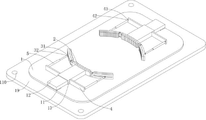
FIG. 1 is a schematic structural view of the present invention;
FIG. 2 is an enlarged structural view of a clamping assembly according to the present invention;
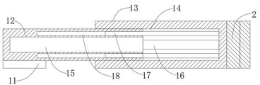
FIG. 3 is an enlarged schematic view of the connection structure between the square plate and the square sleeve;
FIG. 4 is a schematic view of the structure of the push rod assembly of the present invention.
In the figure: 1. a jig stage; 2. a clamping assembly; 3. a slider; 4. a side plate; 5. a push rod assembly; 11. a short platen; 12. a square plate; 13. a square sleeve; 14. a slide chamber; 15. an electric cylinder; 16. a top rod; 17. a guide inserting column; 18. a guide post groove; 19. a fixing plate; 110. a fixing hole; 21. a main clamping arc plate; 22. an ear plate; 23. a connecting shaft; 24. rotating the block; 25. the sub-clamping arc plate; 26. a rubber pad; 27. arc-shaped rubber teeth; 28. an arc-shaped chute; 31. a first primary hinge block; 32. a first sub hinge block; 41. a second main hinge block; 42. a second sub hinge block; 51. a telescopic main rod; 52. a telescopic slave rod; 53. a telescopic groove; 54. a remote control motor; 55. a screw rod; 56. a cavity; 57. a threaded sleeve; 58. a limiting chute; 59. and a limiting sliding block.
Detailed Description
The technical solutions in the embodiments of the present invention will be clearly and completely described below with reference to the drawings in the embodiments of the present invention, and it is obvious that the described embodiments are only a part of the embodiments of the present invention, and not all of the embodiments. All other embodiments, which can be derived by a person skilled in the art from the embodiments given herein without making any creative effort, shall fall within the protection scope of the present invention.
Example 1:
referring to fig. 1-4, the present invention provides a technical solution: an automatic rapid fixture tooling system for a round workpiece comprises a fixture table 1, wherein two short table plates 11 are fixedly connected to the top surfaces of two sides of the fixture table 1 respectively, two square plates 12 are fixedly connected to the top surfaces of the two short table plates 11 respectively, two square sleeves 13 are slidably sleeved at the ends, close to each other, of the two square plates 12 respectively, two clamping components 2 are fixedly connected to the ends, close to each other, of the two square sleeves 13 respectively, and the bottom surfaces of the square sleeves 13 contact the surfaces of the short table plates 11;
the clamping assembly 2 comprises a main clamping arc plate 21 fixedly connected to the end part of the square sleeve 13, two lug plates 22 are fixedly connected to two sides of the main clamping arc plate 21 respectively, two connecting shafts 23 are fixedly connected to the two lug plates 22 respectively, two rotating blocks 24 are rotatably connected to the two connecting shafts 23 respectively, and one ends, far away from the main clamping arc plate 21, of the two rotating blocks 24 are fixedly connected to two sub-clamping arc plates 25 respectively.
Example 2:
referring to fig. 1-2, two arc chutes 28 are respectively formed on one side of the two sub-clamping arc plates 25 close to the square sleeve 13, two sliders 3 are respectively slidably connected in the two arc chutes 28, a first main hinge block 31 is fixedly connected to a side wall of each slider 3, and the first sub-hinge block 32 is rotatably connected to the first main hinge block 31.
Referring to fig. 1-2, two side plates 4 are fixedly connected to two sides of one end of the square sleeve 13 away from the clamping assembly 2, a second main hinge block 41 is fixedly connected to one side of the side plate 4 close to the clamping assembly 2, the second main hinge block 41 is rotatably connected to a second sub hinge block 42, and the push rod assembly 5 is fixedly connected between the first sub hinge block 32 and the second sub hinge block 42.
Referring to fig. 1-2, the main clamping arc plate 21 and the sub-clamping arc plate 25 are fixedly connected to a rubber pad 26 on the side away from the square sleeve 13, and a plurality of arc-shaped rubber teeth 27 are uniformly and vertically fixedly connected to the side wall of the rubber pad 26, and the arc-shaped rubber teeth 27 contact the edge of the workpiece and deform to ensure the clamping stability.
Referring to fig. 3, a sliding cavity 14 is formed in one side of a square sleeve 13 close to a square plate 12, the square plate 12 is inserted into the sliding cavity 14 in a sliding manner, one end of the square plate 12, which is located in the sliding cavity 14, is fixedly embedded in an electric cylinder 15, the end of the electric cylinder 15 is fixedly connected with an ejector rod 16, the ejector rod 16 contacts with the inner wall of the sliding cavity 14, a plurality of guide inserting columns 17 are horizontally and fixedly connected to the inner wall of the sliding cavity 14, a plurality of guide column grooves 18 are respectively formed in one end of the square plate 12, which is located in the sliding cavity 14, corresponding to the plurality of guide inserting columns 17, the guide inserting columns 17 are inserted into the guide column grooves 18 in a sliding manner, and the electric cylinder 15 drives two clamping assemblies 2 to move so as to clamp a workpiece.
Referring to fig. 4, the push rod assembly 5 includes a telescopic main rod 51 fixedly connected to the second sub-hinge block 42 and a telescopic slave rod 52 fixedly connected to the first sub-hinge block 32, a telescopic slot 53 is formed at an end of the telescopic main rod 51 far away from the second sub-hinge block 42, one end of the telescopic slave rod 52 far away from the first sub-hinge block 32 is slidably inserted into the telescopic slot 53, a limit sliding slot 58 is formed in an inner side wall of the telescopic slot 53, one end of the telescopic slave rod 52 located in the telescopic slot 53 is fixedly connected to a limit sliding block 59, and the limit sliding block 59 is slidably connected to the limit sliding slot 58.
Referring to fig. 4, one end of the telescopic slot 53, which is far from the telescopic slave rod 52, is fixedly connected to a remote control motor 54, one end of the telescopic slave rod 52, which is located in the telescopic slot 53, is provided with a cavity 56, the end of the remote control motor 54 is fixedly connected to a lead screw 55, the lead screw 55 is located in the telescopic slot 53 and the cavity 56, one end of the cavity 56, which is located in the telescopic slot 53, is fixedly sleeved with a threaded sleeve 57, the lead screw 55 is engaged with the threaded sleeve 57, after the remote control motor 54 is started, the length of the push rod assembly 5 is changed, and then the rotation angle of the sub-clamping arc plate 25 is adjusted, so that the sub-clamping arc plate 25 is in close contact with the edge of the workpiece.
Referring to fig. 1, a fixing plate 19 is fixedly connected to the bottom surface of the outer side wall of the fixture table 1, a plurality of fixing holes 110 are vertically formed in the fixing plate 19, and the fixture table 1 is fixed at a desired position by the fixing plate 19.
Example 3:
when the clamping device is used, the clamp table 1 is fixed at a required position through the fixing plate 19, then a round workpiece is placed on the surface of the clamp table 1, then the two electric cylinders 15 are started, the two clamping components 2 are driven to move through the electric cylinders 15, the workpiece is clamped, during clamping, the two main clamping arc plates 21 on the two clamping components 2 clamp the diameter edge of the workpiece, then the remote control motor 54 is started, after the remote control motor 54 is started, the length of the push rod component 5 is changed, and further the rotating angle of the sub clamping arc plates 25 is adjusted, so that the sub clamping arc plates 25 are in close contact with the edge of the workpiece, and the clamping of the workpiece can be completed, the two ends of the main clamping arc plates 21 at the clamping components 2 are respectively and rotatably connected with the two sub clamping arc plates 25, when the workpiece is clamped, the two main clamping arc plates 21 on the two clamping components 2 clamp the diameter edge of the workpiece, and the sub clamping arc plates 25 are attached to the edge of the workpiece through rotation, the contact area during clamping is ensured, and the stability of clamping is ensured.
Although embodiments of the present invention have been shown and described, it will be appreciated by those skilled in the art that changes, modifications, substitutions and alterations can be made in these embodiments without departing from the principles and spirit of the invention, the scope of which is defined in the appended claims and their equivalents.
Claims (8)
1. The utility model provides an automatic swift anchor clamps frock system to circular workpiece, includes anchor clamps platform (1), its characterized in that:
the top surfaces of two sides of the fixture table (1) are fixedly connected with two short table plates (11) respectively, the top surfaces of the two short table plates (11) are fixedly connected with two square plates (12) respectively, one ends, close to each other, of the two square plates (12) are sleeved with two square sleeves (13) in a sliding mode respectively, one ends, close to each other, of the two square sleeves (13) are fixedly connected with two clamping components (2) respectively, and the bottom surfaces of the square sleeves (13) are in contact with the surfaces of the short table plates (11);
the clamping assembly (2) comprises a main clamping arc plate (21) fixedly connected to the end portion of the square sleeve (13), two lug plates (22) are fixedly connected to two sides of the main clamping arc plate (21) respectively, two connecting shafts (23) are fixedly connected to the two lug plates (22) respectively, two rotating blocks (24) are rotatably connected to the connecting shafts (23) respectively, and the rotating blocks (24) are far away from one end of the main clamping arc plate (21) and fixedly connected with two sub-clamping arc plates (25) respectively.
2. The automatic quick clamp tooling system for the circular workpiece according to claim 1, characterized in that: two arc-shaped sliding grooves (28) are respectively formed in one side, close to the square sleeve (13), of each of the two sub-clamping arc plates (25), two sliding blocks (3) are respectively connected in the two arc-shaped sliding grooves (28) in a sliding mode, a first main hinging block (31) is fixedly connected to the side wall of each sliding block (3), and a first sub-hinging block (32) is rotatably connected to the first main hinging block (31).
3. The automatic quick clamp tooling system for the circular workpiece as claimed in claim 2, wherein: the square sleeve (13) is fixedly connected with two side plates (4) at two sides of one end, far away from the clamping assembly (2), of each square sleeve, one side, close to the clamping assembly (2), of each side plate (4) is fixedly connected with a second main hinging block (41), the second main hinging block (41) is rotatably connected with a second sub hinging block (42), and a push rod assembly (5) is fixedly connected between the first sub hinging block (32) and the second sub hinging block (42).
4. The automatic quick clamp tooling system for the circular workpiece according to claim 1, characterized in that: one sides of the main clamping arc plate (21) and the sub clamping arc plate (25) far away from the square sleeve (13) are fixedly connected with rubber pads (26), and the side walls of the rubber pads (26) are uniformly and vertically fixedly connected with a plurality of arc-shaped rubber teeth (27).
5. The automatic quick clamp tooling system for the circular workpiece according to claim 1, characterized in that: one side, close to the square plate (12), of the square sleeve (13) is provided with a sliding cavity (14), the square plate (12) is inserted in the sliding cavity (14) in a sliding mode, one end, located in the sliding cavity (14), of the square plate (12) is fixedly embedded with an electric cylinder (15), the end portion of the electric cylinder (15) is fixedly connected with an ejector rod (16), the ejector rod (16) is in contact with the inner wall of the sliding cavity (14), the inner side wall of the sliding cavity (14) is horizontally and fixedly connected with a plurality of guide inserting columns (17), one end, located in the sliding cavity (14), of the square plate (12) is provided with a plurality of guide column grooves (18) corresponding to the positions of the plurality of guide inserting columns (17), and the guide inserting columns (17) are inserted in the guide column grooves (18) in a sliding mode.
6. The automatic quick clamp tooling system for the circular workpiece according to claim 3, characterized in that: push rod assembly (5) include flexible mobile jib (51) and the flexible slave rod (52) of rigid coupling on the sub-articulated piece (42) of second on first sub-articulated piece (32) of rigid coupling on, flexible mobile jib (51) are kept away from sub-articulated piece (42) one end of second and are seted up flexible groove (53), flexible from pole (52) keep away from first sub-articulated piece (32) one end and slide and peg graft in flexible groove (53), spacing spout (58) are seted up to flexible groove (53) inside wall, flexible slave rod (52) are located flexible groove (53) one end lateral wall rigid coupling stop block (59), stop block (59) sliding connection is in spacing spout (58).
7. The automatic quick clamp tooling system for the circular workpiece as claimed in claim 6, wherein: keep away from flexible follow pole (52) one end rigid coupling remote control motor (54) in flexible groove (53), flexible follow pole (52) are located flexible groove (53) one end and set up cavity (56), remote control motor (54) tip rigid coupling lead screw (55), lead screw (55) are located flexible groove (53) and cavity (56), cavity (56) are located flexible groove (53) one end fixed cover and connect threaded sleeve (57), lead screw (55) meshing connection threaded sleeve (57).
8. The automatic quick clamp tooling system for the circular workpiece according to claim 1, characterized in that: the fixture platform (1) is characterized in that a fixing plate (19) is fixedly connected to the bottom surface of the outer side wall of the fixture platform (1), and a plurality of fixing holes (110) are vertically formed in the fixing plate (19).
Priority Applications (1)
| Application Number | Priority Date | Filing Date | Title |
|---|---|---|---|
| CN202111666342.3A CN114406745A (en) | 2021-12-31 | 2021-12-31 | Automatic quick clamp tooling system for round workpieces |
Applications Claiming Priority (1)
| Application Number | Priority Date | Filing Date | Title |
|---|---|---|---|
| CN202111666342.3A CN114406745A (en) | 2021-12-31 | 2021-12-31 | Automatic quick clamp tooling system for round workpieces |
Publications (1)
| Publication Number | Publication Date |
|---|---|
| CN114406745A true CN114406745A (en) | 2022-04-29 |
Family
ID=81270508
Family Applications (1)
| Application Number | Title | Priority Date | Filing Date |
|---|---|---|---|
| CN202111666342.3A Withdrawn CN114406745A (en) | 2021-12-31 | 2021-12-31 | Automatic quick clamp tooling system for round workpieces |
Country Status (1)
| Country | Link |
|---|---|
| CN (1) | CN114406745A (en) |
Cited By (2)
| Publication number | Priority date | Publication date | Assignee | Title |
|---|---|---|---|---|
| CN116079463A (en) * | 2023-01-17 | 2023-05-09 | 群志数控装备(苏州)有限公司 | Workpiece clamping device of vertical machining center |
| CN118303706A (en) * | 2024-05-17 | 2024-07-09 | 浙江锐奇鞋业有限公司 | Sole stamping and leveling device and application method thereof |
-
2021
- 2021-12-31 CN CN202111666342.3A patent/CN114406745A/en not_active Withdrawn
Cited By (2)
| Publication number | Priority date | Publication date | Assignee | Title |
|---|---|---|---|---|
| CN116079463A (en) * | 2023-01-17 | 2023-05-09 | 群志数控装备(苏州)有限公司 | Workpiece clamping device of vertical machining center |
| CN118303706A (en) * | 2024-05-17 | 2024-07-09 | 浙江锐奇鞋业有限公司 | Sole stamping and leveling device and application method thereof |
Similar Documents
| Publication | Publication Date | Title |
|---|---|---|
| CN210677777U (en) | Clamping mechanism for rotary workbench | |
| CN114406745A (en) | Automatic quick clamp tooling system for round workpieces | |
| CN209774013U (en) | Drilling machine tool fixture table | |
| CN215146977U (en) | Workpiece clamp for machining center | |
| CN207480096U (en) | A kind of rack-and-pinion synchronous fixture | |
| CN107309461B (en) | Main chord member end hole processing machine for tower body | |
| CN211589264U (en) | Rear sleeve machining clamp | |
| CN215469724U (en) | Machining clamp structure | |
| CN212683170U (en) | Plunger bushing processing waist type hole anchor clamps | |
| CN210232310U (en) | Anchor clamps of high accuracy cell-phone frame processing | |
| CN212793993U (en) | Accurate positioner of high-speed linear rail machining center | |
| CN210938182U (en) | Connecting rod end face milling device | |
| CN220445747U (en) | Clamp work piece tool | |
| CN220971522U (en) | Automatic clamping tool | |
| CN216126761U (en) | Flexible support arc plate machining tool clamp | |
| CN219402691U (en) | Workpiece mounting fixture for tapping machine | |
| CN212526922U (en) | Mobile phone rear shell clamp capable of adjusting station | |
| CN219703718U (en) | Chamfering device special for elastic pin | |
| CN218051451U (en) | Portable universal fixture for mechanical parts | |
| CN214685342U (en) | Positioning fixture of vertical machining center | |
| CN221186177U (en) | Clamp convenient for loading and unloading | |
| CN217494183U (en) | Engine die casting machine tooling anchor clamps | |
| CN221185621U (en) | Positioning and supporting device for machining part machine tool | |
| CN215788305U (en) | Round piece clamping tool | |
| CN218425076U (en) | Cylindrical part stamping device |
Legal Events
| Date | Code | Title | Description |
|---|---|---|---|
| PB01 | Publication | ||
| PB01 | Publication | ||
| WW01 | Invention patent application withdrawn after publication |
Application publication date: 20220429 |
|
| WW01 | Invention patent application withdrawn after publication |