CN114379999B - Automatic unloading system of container - Google Patents
Automatic unloading system of container Download PDFInfo
- Publication number
- CN114379999B CN114379999B CN202210281729.5A CN202210281729A CN114379999B CN 114379999 B CN114379999 B CN 114379999B CN 202210281729 A CN202210281729 A CN 202210281729A CN 114379999 B CN114379999 B CN 114379999B
- Authority
- CN
- China
- Prior art keywords
- forklift
- grabbing
- gantry crane
- front side
- lifting
- Prior art date
- Legal status (The legal status is an assumption and is not a legal conclusion. Google has not performed a legal analysis and makes no representation as to the accuracy of the status listed.)
- Active
Links
Images


Classifications
-
- B—PERFORMING OPERATIONS; TRANSPORTING
- B65—CONVEYING; PACKING; STORING; HANDLING THIN OR FILAMENTARY MATERIAL
- B65G—TRANSPORT OR STORAGE DEVICES, e.g. CONVEYORS FOR LOADING OR TIPPING, SHOP CONVEYOR SYSTEMS OR PNEUMATIC TUBE CONVEYORS
- B65G21/00—Supporting or protective framework or housings for endless load-carriers or traction elements of belt or chain conveyors
- B65G21/10—Supporting or protective framework or housings for endless load-carriers or traction elements of belt or chain conveyors movable, or having interchangeable or relatively movable parts; Devices for moving framework or parts thereof
- B65G21/14—Supporting or protective framework or housings for endless load-carriers or traction elements of belt or chain conveyors movable, or having interchangeable or relatively movable parts; Devices for moving framework or parts thereof to allow adjustment of length or configuration of load-carrier or traction element
-
- B—PERFORMING OPERATIONS; TRANSPORTING
- B65—CONVEYING; PACKING; STORING; HANDLING THIN OR FILAMENTARY MATERIAL
- B65G—TRANSPORT OR STORAGE DEVICES, e.g. CONVEYORS FOR LOADING OR TIPPING, SHOP CONVEYOR SYSTEMS OR PNEUMATIC TUBE CONVEYORS
- B65G13/00—Roller-ways
- B65G13/02—Roller-ways having driven rollers
- B65G13/06—Roller driving means
-
- B—PERFORMING OPERATIONS; TRANSPORTING
- B65—CONVEYING; PACKING; STORING; HANDLING THIN OR FILAMENTARY MATERIAL
- B65G—TRANSPORT OR STORAGE DEVICES, e.g. CONVEYORS FOR LOADING OR TIPPING, SHOP CONVEYOR SYSTEMS OR PNEUMATIC TUBE CONVEYORS
- B65G15/00—Conveyors having endless load-conveying surfaces, i.e. belts and like continuous members, to which tractive effort is transmitted by means other than endless driving elements of similar configuration
- B65G15/30—Belts or like endless load-carriers
- B65G15/32—Belts or like endless load-carriers made of rubber or plastics
-
- B—PERFORMING OPERATIONS; TRANSPORTING
- B65—CONVEYING; PACKING; STORING; HANDLING THIN OR FILAMENTARY MATERIAL
- B65G—TRANSPORT OR STORAGE DEVICES, e.g. CONVEYORS FOR LOADING OR TIPPING, SHOP CONVEYOR SYSTEMS OR PNEUMATIC TUBE CONVEYORS
- B65G65/00—Loading or unloading
- B65G65/30—Methods or devices for filling or emptying bunkers, hoppers, tanks, or like containers, of interest apart from their use in particular chemical or physical processes or their application in particular machines, e.g. not covered by a single other subclass
- B65G65/34—Emptying devices
-
- B—PERFORMING OPERATIONS; TRANSPORTING
- B66—HOISTING; LIFTING; HAULING
- B66F—HOISTING, LIFTING, HAULING OR PUSHING, NOT OTHERWISE PROVIDED FOR, e.g. DEVICES WHICH APPLY A LIFTING OR PUSHING FORCE DIRECTLY TO THE SURFACE OF A LOAD
- B66F9/00—Devices for lifting or lowering bulky or heavy goods for loading or unloading purposes
- B66F9/06—Devices for lifting or lowering bulky or heavy goods for loading or unloading purposes movable, with their loads, on wheels or the like, e.g. fork-lift trucks
- B66F9/075—Constructional features or details
- B66F9/12—Platforms; Forks; Other load supporting or gripping members
- B66F9/16—Platforms; Forks; Other load supporting or gripping members inclinable relative to mast
-
- B—PERFORMING OPERATIONS; TRANSPORTING
- B66—HOISTING; LIFTING; HAULING
- B66F—HOISTING, LIFTING, HAULING OR PUSHING, NOT OTHERWISE PROVIDED FOR, e.g. DEVICES WHICH APPLY A LIFTING OR PUSHING FORCE DIRECTLY TO THE SURFACE OF A LOAD
- B66F9/00—Devices for lifting or lowering bulky or heavy goods for loading or unloading purposes
- B66F9/06—Devices for lifting or lowering bulky or heavy goods for loading or unloading purposes movable, with their loads, on wheels or the like, e.g. fork-lift trucks
- B66F9/075—Constructional features or details
- B66F9/12—Platforms; Forks; Other load supporting or gripping members
- B66F9/18—Load gripping or retaining means
- B66F9/181—Load gripping or retaining means by suction means
-
- B—PERFORMING OPERATIONS; TRANSPORTING
- B66—HOISTING; LIFTING; HAULING
- B66F—HOISTING, LIFTING, HAULING OR PUSHING, NOT OTHERWISE PROVIDED FOR, e.g. DEVICES WHICH APPLY A LIFTING OR PUSHING FORCE DIRECTLY TO THE SURFACE OF A LOAD
- B66F9/00—Devices for lifting or lowering bulky or heavy goods for loading or unloading purposes
- B66F9/06—Devices for lifting or lowering bulky or heavy goods for loading or unloading purposes movable, with their loads, on wheels or the like, e.g. fork-lift trucks
- B66F9/075—Constructional features or details
- B66F9/20—Means for actuating or controlling masts, platforms, or forks
- B66F9/24—Electrical devices or systems
Abstract
The invention relates to an automatic container unloading system which comprises a forklift and a grabbing mechanism arranged on the front side of the forklift, wherein the grabbing mechanism comprises a gantry crane arranged on the front side of the forklift, a grabbing part connected with the gantry crane, a telescopic belt arranged on the left side or the right side of the forklift and a conveying assembly arranged on the front side of the forklift, the conveying assembly comprises two groups of electric rollers which are arranged vertically, the grabbing part is erected above the electric rollers, the end part of one group of electric rollers is rotatably connected with one end of the telescopic belt, and the other end of the telescopic belt is rotatably connected with the rear part of the forklift. According to the invention, unmanned operation is realized through the grabbing mechanism in front of the forklift, the labor cost is saved, meanwhile, the risk of artificial infection during unloading and loading of cold chain transportation products is effectively avoided, meanwhile, the matching relation between the gantry crane and the grabbing part can not influence the work of the grabbing part while the electric roller conveys goods, and the box picking efficiency is effectively improved.
Description
Technical Field
The invention relates to the technical field of loading and unloading machinery, in particular to an automatic unloading system for a container.
Background
The biggest success of the container lies in the standardization of products and a whole set of transportation system established by the containers, which can realize the standardization of a natural object carrying dozens of tons and is widely applied to the industries such as ports and docks, train transportation, automobile transportation and the like on the basis of the standardization. The following disadvantages still exist when the container is unloaded: firstly, the traditional unloading operation has low automation degree, is more dependent on manpower, is labor-consuming and time-consuming, and is not suitable for flow unloading treatment; secondly, when the forklift is used for loading and unloading goods, the space in the container is limited, so that the goods in the container are inconvenient to take and transfer, and the loading and unloading efficiency is low, so that further improvement is needed.
Disclosure of Invention
The invention aims to overcome the defects in the prior art and provide an automatic unloading system for a container, which can realize an efficient unloading process of the container.
The invention is realized by the following technical scheme:
the utility model provides an automatic unloading system of container, includes fork truck, installs in the mechanism that snatchs of fork truck front side, snatch the mechanism including locating the longmen crane of fork truck front side, the portion of snatching that links to each other with the longmen crane, locate the flexible belt on fork truck left side or right side and locate the conveying subassembly of fork truck front side, conveying subassembly includes the motorized pulley of two sets of mutually perpendicular settings, the portion of snatching erects in the motorized pulley top, and wherein the tip of a set of motorized pulley is rotated with the one end of flexible belt and is connected, the other end and the fork truck rear portion of flexible belt rotate and are connected.
According to the above technical scheme, preferably, the portion of snatching including locating the link of longmen crane top, rotate connect in the link front side snatch the sucking disc and locate the link and snatch the turning device between the sucking disc, turning device can drive and snatch the sucking disc and be horizontality and vertical state.
According to the above technical scheme, preferably, the turning device includes an electric cylinder fixedly connected with the connecting frame, a connecting plate hinged to the end of the electric cylinder through an indirect plate, and a rotating shaft rotatably connected to the front side of the connecting frame, the connecting plate is fixedly connected with the rotating shaft, and the grabbing sucker is fixedly connected with the connecting plate.
According to the technical scheme, preferably, two sides of the conveying assembly are connected with two sides of the gantry crane through the first screw rod modules.
According to the technical scheme, preferably, the upper part of the gantry crane is connected with the connecting frame through the second screw rod module.
According to the technical scheme, preferably, the gantry crane comprises two opposite lifting components, each lifting component comprises two lifting plates, a fixed end, a linear motion sliding table and side plates, the middle parts of the lifting plates are hinged in a crossed mode, the fixed end is hinged to the lower end of one of the lifting plates, the linear motion sliding table is hinged to the lower end of the other lifting plate, the side plates are hinged to the upper ends of the two lifting plates respectively, sliding holes are formed in the surfaces of the side plates in the horizontal direction, and the upper ends of the lifting plates hinged to the fixed ends can slide in the sliding holes.
The invention has the beneficial effects that:
according to the invention, unmanned operation is realized through the grabbing mechanism in front of the forklift, the labor cost is saved, meanwhile, the risk of artificial infection during unloading and loading of cold chain transportation products is effectively avoided, meanwhile, the matching relationship between the gantry crane and the grabbing part can not influence the work of the grabbing part while the electric roller conveys goods, the box picking efficiency is effectively improved, and the forklift has better application and popularization values.
Drawings
Fig. 1 is a schematic perspective view of the present invention.
Fig. 2 is a schematic perspective view of the present invention.
Fig. 3 is a schematic perspective view of the grasping portion of the present invention.
Fig. 4 is a side view of the grasping portion of the present invention.
Fig. 5 is a side view of the gripping mechanism of the present invention with the gripping suction cups in a vertical position.
Fig. 6 is a side view of the gripping mechanism of the present invention when the gripping suction cups are in a horizontal position.
Fig. 7 is a side view of a portion of the grasping mechanism of the present invention.
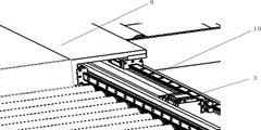
Figure 8 is a schematic perspective structure diagram of the connection position of the gantry crane and the connecting frame.
In the figure: 1. a forklift; 2. a grabbing mechanism; 3. an electric roller; 4. a retractable belt; 5. grabbing a sucker; 6. a connecting plate; 7. a rotating shaft; 8. a connecting frame; 9. an electric cylinder; 10. a second lead screw module; 11. a side plate; 12. a sliding channel; 13. a first lead screw module; 14. a fixed end; 15. a lifting plate; 16. and (4) linearly moving the sliding table.
Detailed Description
In order to make the technical solutions of the present invention better understood by those skilled in the art, the present invention will be further described in detail with reference to the accompanying drawings and preferred embodiments. All other embodiments, which can be derived by a person skilled in the art from the embodiments given herein without making any creative effort, shall fall within the protection scope of the present invention.
In the description of the present invention, it should be noted that the terms "center", "upper", "lower", "left", "right", "vertical", "horizontal", "inner", "outer", and the like indicate orientations or positional relationships based on the orientations or positional relationships shown in the drawings, and are only for convenience of describing the invention and simplifying the description, but do not indicate or imply that the device or element referred to must have a specific orientation, be constructed and operated in a specific orientation, and thus, should not be construed as limiting the invention.
As shown in the figure, the forklift comprises a forklift 1 and a grabbing mechanism 2 arranged on the front side of the forklift 1, wherein the grabbing mechanism 2 comprises a gantry crane arranged on the front side of the forklift 1, a grabbing part connected with the gantry crane, a telescopic belt 4 arranged on the left side or the right side of the forklift 1 and a conveying component arranged on the front side of the forklift 1, specifically, the gantry crane is positioned on a fork on the front side of the forklift 1, and the grabbing part is connected with the conveying component and arranged on the gantry crane. The conveying assembly comprises two groups of electric rollers 3 which are perpendicular to each other, the grabbing part is erected above the electric rollers 3, the end part of one group of electric rollers 3 is rotatably connected with one end of a telescopic belt 4, and the other end of the telescopic belt 4 is rotatably connected with the rear part of the forklift 1. The grabbing mechanism 2 is installed on the front side of the forklift 1, and the whole large-stroke lifting movement of the equipment can be achieved by means of the lifting mechanism of the forklift 1, so that the purpose of sucking all boxes from the first row to the last row is achieved, and the forklift 1 can ascend and descend in the advancing process or draw boxes on an inclined plane with a certain gradient by means of the forward tilting mechanism of the forklift 1. According to the invention, unmanned operation is realized through the grabbing mechanism 2 in front of the forklift 1, labor cost is saved, meanwhile, the risk of artificial infection during unloading and loading of cold chain transportation products is effectively avoided, meanwhile, the matching relationship between the gantry crane and the grabbing part can not influence the work of the grabbing part while the electric roller 3 conveys goods, the box drawing efficiency is effectively improved, and the application and popularization values are better.
According to the above embodiment, preferably, the grabbing part includes the connecting frame 8 arranged above the gantry crane, the grabbing sucker 5 rotatably connected to the front side of the connecting frame 8, and the turning device arranged between the connecting frame 8 and the grabbing sucker 5, the turning device can drive the grabbing sucker 5 to be in a horizontal state and a vertical state, and in this case, the grabbing sucker 5 is preferably a sponge sucker. Wherein, turning device includes with the electric jar 9 of 8 rigid couplings of link, through indirect board articulated in the connecting plate 6 of 9 tip of electric jar and rotate the pivot 7 of connecting in the 8 front sides of link, wherein indirect board both ends are articulated with connecting plate 6, 9 tip of electric jar respectively, and it sets up and is used for connecting 9 tip of electric jar and connecting plate 6, connecting plate 6 and pivot 7 rigid couplings, snatch sucking disc 5 and connecting plate 6 rigid couplings. In the time of the actual work, the flexible drive of accessible electric cylinder 9 links to each other with connecting plate 6 snatchs sucking disc 90 rotations, because the case of top layer is very near above the container is inside apart from the container, can will snatch sucking disc 5 and rotate the case of top layer in the container to the vertical state and snatch, effectively deal with the limited difficult point in container inner space, when snatching the goods outside the top layer, can will snatch sucking disc 5 and rotate to the horizontality, the portion of snatching is raised to the longmen crane this moment, can not influence the work of the portion of snatching when motorized pulley 3 conveys goods, the working time is saved, and the work efficiency is improved.
According to the above embodiment, preferably, two sides of the conveying assembly are connected with two sides of the gantry crane through the first lead screw module 13, so as to drive the gantry crane to move along the direction close to or far away from the forklift 1, and in addition, the upper part of the gantry crane is connected with the connecting frame 8 through the second lead screw module 10. Above-mentioned setting makes snatching 5 accessible longmen erectors and realizes altitude mixture control, realizes the regulation of vertical direction simultaneously through first lead screw module 13 and second lead screw module 10, and then makes snatch 5 can realize the removal of the three direction of XYZ in the cartesian coordinate according to the in-service use demand, and the stack motion through multiple action is in order to improve the adaptability of different container sizes, realizes the high-efficient rational utilization of resource.
According to the above embodiment, preferably, the gantry crane includes two lifting assemblies oppositely arranged, each lifting assembly includes two lifting plates 15 with middle parts hinged in a crossing manner, a fixed end 14 hinged to the lower end of one lifting plate 15, a linear motion sliding table 16 hinged to the lower end of the other lifting plate 15, and side plates 11 hinged to the upper ends of the two lifting plates 15 respectively, a sliding hole 12 is formed in the surface of each side plate 11 along the horizontal direction, and the upper end of each lifting plate 15 hinged to the fixed end 14 can slide in the sliding hole 12. In this example, the stroke of the linear motion sliding table 16 is controlled by a servo motor, so that the height of the grabbing part in the vertical direction is accurately controlled.
According to the invention, unmanned operation is realized through the grabbing mechanism 2 in front of the forklift 1, labor cost is saved, meanwhile, the risk of artificial infection during unloading and loading of cold chain transportation products is effectively avoided, meanwhile, the matching relation between the gantry crane and the grabbing part can not influence the work of the grabbing part while the electric roller 3 conveys goods, the box drawing efficiency is effectively improved, and the forklift has better application and popularization values.
The foregoing is only a preferred embodiment of the present invention, and it should be noted that, for those skilled in the art, various modifications and decorations can be made without departing from the principle of the present invention, and these modifications and decorations should also be regarded as the protection scope of the present invention.
Claims (3)
1. An automatic unloading system of a container is characterized by comprising a forklift and a grabbing mechanism arranged on the front side of the forklift, wherein the grabbing mechanism comprises a gantry crane arranged on the front side of the forklift, a grabbing part connected with the gantry crane, a telescopic belt arranged on the left side or the right side of the forklift and a conveying assembly arranged on the front side of the forklift, the gantry crane is positioned on a pallet fork on the front side of the forklift, the conveying assembly comprises two groups of electric rollers which are arranged vertically, the grabbing part is erected above the electric rollers, the end part of one group of electric rollers is rotationally connected with one end of the telescopic belt, the other end of the telescopic belt is rotationally connected with the rear part of the forklift, the grabbing part comprises a connecting frame arranged above the forklift, a grabbing sucker rotationally connected to the front side of the connecting frame and a turnover device arranged between the connecting frame and the grabbing sucker, and the turnover device can drive the grabbing sucker to be in a horizontal state and a vertical state, the conveying assembly is characterized in that two sides of the conveying assembly are connected with two sides of the gantry crane through the first lead screw modules, the upper portion of the gantry crane is connected with the connecting frame through the second lead screw modules, the grabbing sucker can be adjusted in height through the gantry crane, meanwhile, the vertical direction is adjusted through the first lead screw modules and the second lead screw modules, the grabbing sucker can move in the three directions of XYZ in Cartesian coordinates according to actual use requirements, the grabbing part can be lifted by the gantry crane, and the work of the grabbing part cannot be influenced when the electric roller conveys goods.
2. An automatic unloading system for containers as claimed in claim 1, wherein said turning unit includes an electric cylinder fixedly connected to the connecting frame, a connecting plate hinged to the end of the electric cylinder through an indirect plate, and a rotary shaft rotatably connected to the front side of the connecting frame, said connecting plate being fixedly connected to the rotary shaft, and said gripping suction cup being fixedly connected to the connecting plate.
3. An automatic unloading system for containers as claimed in claim 1, wherein the gantry crane includes two oppositely disposed lifting assemblies, each lifting assembly includes two lifting plates hinged to each other at their middle portions, a fixed end hinged to the lower end of one of the lifting plates, a linear sliding table hinged to the lower end of the other lifting plate, and side plates hinged to the upper ends of the two lifting plates, and a sliding hole is formed in the surface of each side plate along the horizontal direction, wherein the upper end of the lifting plate hinged to the fixed end can slide in the sliding hole.
Priority Applications (1)
| Application Number | Priority Date | Filing Date | Title |
|---|---|---|---|
| CN202210281729.5A CN114379999B (en) | 2022-03-22 | 2022-03-22 | Automatic unloading system of container |
Applications Claiming Priority (1)
| Application Number | Priority Date | Filing Date | Title |
|---|---|---|---|
| CN202210281729.5A CN114379999B (en) | 2022-03-22 | 2022-03-22 | Automatic unloading system of container |
Publications (2)
| Publication Number | Publication Date |
|---|---|
| CN114379999A CN114379999A (en) | 2022-04-22 |
| CN114379999B true CN114379999B (en) | 2022-06-07 |
Family
ID=81205689
Family Applications (1)
| Application Number | Title | Priority Date | Filing Date |
|---|---|---|---|
| CN202210281729.5A Active CN114379999B (en) | 2022-03-22 | 2022-03-22 | Automatic unloading system of container |
Country Status (1)
| Country | Link |
|---|---|
| CN (1) | CN114379999B (en) |
Family Cites Families (8)
| Publication number | Priority date | Publication date | Assignee | Title |
|---|---|---|---|---|
| AUPQ183099A0 (en) * | 1999-07-27 | 1999-08-19 | Schmidt, Hans H. | Container handling apparatus or cradle |
| JP5371019B2 (en) * | 2008-10-17 | 2013-12-18 | エイチエイチ インテリテック エーピーエス | Lifting vehicle |
| CN213008210U (en) * | 2020-04-03 | 2021-04-20 | 江苏斯诺供应链管理有限公司 | Commodity circulation transportation small handcart |
| CN112499246A (en) * | 2020-12-15 | 2021-03-16 | 中车株洲车辆有限公司 | Box type cargo handling equipment |
| CN112919148B (en) * | 2021-02-08 | 2023-03-21 | 青岛大地厚生科技有限责任公司 | Non-contact type cold chain container drawing, disinfecting, loading and unloading intelligent equipment |
| CN113233216A (en) * | 2021-06-08 | 2021-08-10 | 曜琅智慧科技产业(天津)有限公司 | Box drawing robot and using method thereof |
| CN113291774B (en) * | 2021-06-30 | 2021-12-17 | 青岛科捷机器人有限公司 | Loading and unloading integrated machine and automatic loading and unloading system of container |
| CN113697491B (en) * | 2021-08-31 | 2022-10-28 | 青岛创科未来机器人科技有限公司 | Cold-chain container carton cargo handling equipment and method |
-
2022
- 2022-03-22 CN CN202210281729.5A patent/CN114379999B/en active Active
Also Published As
| Publication number | Publication date |
|---|---|
| CN114379999A (en) | 2022-04-22 |
Similar Documents
| Publication | Publication Date | Title |
|---|---|---|
| CN108750690A (en) | Suction means, de-stacking device and de-stacking method | |
| CN108328348B (en) | Movable robot loading and unloading stacker crane and loading and unloading method thereof | |
| WO2021098008A1 (en) | Product picking system and product picking method | |
| WO2021098007A1 (en) | Manipulator | |
| CN113305819A (en) | Mechanical arm for carrying logistics | |
| CN114379999B (en) | Automatic unloading system of container | |
| CN112338893A (en) | Full-automatic loading and unloading goods robot | |
| WO2021098006A1 (en) | Picking system and picking method | |
| CN210392962U (en) | Shelf board stacking device for goods shelf | |
| CN209796915U (en) | Full-automatic carloader of intelligence | |
| CN209321748U (en) | A kind of mobile robot of lateral double half shovels | |
| CN216807059U (en) | Automatic change conveyor and equipment | |
| CN215478198U (en) | Container loading and unloading flat plate device | |
| WO2023137782A1 (en) | Material tray turnover mechanism | |
| CN213616682U (en) | Full-automatic loading and unloading goods robot | |
| CN212502809U (en) | Reliable arm material handling device | |
| CN113428418A (en) | Double-station circulating type automatic packaging equipment | |
| CN219313879U (en) | Automatic material taking, loading and unloading device | |
| CN216372220U (en) | Robot device for loading articles | |
| CN219238616U (en) | Unstacking device adaptable to logistics boxes with different heights | |
| CN217397877U (en) | Material stacking device | |
| CN214269391U (en) | Semi-automatic stacker crane | |
| CN216822039U (en) | Sole pressing device | |
| CN217915336U (en) | Novel automatic loading and unloading goods manipulator device | |
| CN210193313U (en) | Device that moves of bio-pharmaceuticals smart machine |
Legal Events
| Date | Code | Title | Description |
|---|---|---|---|
| PB01 | Publication | ||
| PB01 | Publication | ||
| SE01 | Entry into force of request for substantive examination | ||
| SE01 | Entry into force of request for substantive examination | ||
| GR01 | Patent grant | ||
| GR01 | Patent grant | ||
| PE01 | Entry into force of the registration of the contract for pledge of patent right | ||
| PE01 | Entry into force of the registration of the contract for pledge of patent right |
Denomination of invention: An automatic container unloading system Effective date of registration: 20221230 Granted publication date: 20220607 Pledgee: Bank of Beijing Limited by Share Ltd. Tianjin branch Pledgor: TIANJIN TONGGUANG GROUP SPECIAL EQUIPMENT Co.,Ltd. Registration number: Y2022120000074 |