CN114319356A - Offshore wind power single-pile foundation construction method and special ship - Google Patents
Offshore wind power single-pile foundation construction method and special ship Download PDFInfo
- Publication number
- CN114319356A CN114319356A CN202111516393.8A CN202111516393A CN114319356A CN 114319356 A CN114319356 A CN 114319356A CN 202111516393 A CN202111516393 A CN 202111516393A CN 114319356 A CN114319356 A CN 114319356A
- Authority
- CN
- China
- Prior art keywords
- pile
- structural steel
- steel pile
- guide frame
- special ship
- Prior art date
- Legal status (The legal status is an assumption and is not a legal conclusion. Google has not performed a legal analysis and makes no representation as to the accuracy of the status listed.)
- Pending
Links
Images


Abstract
The utility model relates to the field of offshore wind power construction, in particular to an offshore wind power single-pile foundation construction method and a special ship. The method comprises the steps of firstly, constructing a fixed guide platform after accurate positioning is carried out according to a piling positioning system; and the platform construction is completed, the special ship crane completes the hoisting and overturning of the steel pile, the steel pile is fed into the guide platform hoop, and after the verticality is adjusted, the steel pile begins to enter mud by self weight, and the completion of the mud entering by self weight is completed. The special ship crane lifts the hydraulic hammer to the pile top, begins to hammer the pile sinking, measures and guarantees the verticality in the process until the pile sinking is finished; and (4) sinking the pile in place, dismantling the guide platform by the special ship, hoisting the auxiliary structure, and moving to the next machine position before the ship is moved.
Description
[ technical field ] A method for producing a semiconductor device
The utility model relates to the field of offshore wind power construction, in particular to an offshore wind power single-pile foundation construction method and a special ship.
[ background of the utility model ]
Offshore wind power generation is one of the low-carbon new energy with the most extensive development and commercial development prospect at present, becomes an important component of an energy system in China, and is vigorously promoted and developed in various countries in the world. The total amount of offshore wind power planning in China exceeds 8000 thousands of kilowatts, the key layout is distributed in coastal provinces and cities such as Jiangsu, Zhejiang, Fujian, Guangdong, Guangxi and the like, and the industrial development prospect is wide. With the development of the domestic offshore wind power industry, small-scale demonstration development is changed into large-scale continuous development and large-scale offshore wind power base and energy island development, wind turbine generators are continuously developed to be large-scale, the offshore distance of a wind field is longer and longer, and the construction sea area is deeper and deeper, so that the offshore wind power construction process and the function of a ship special for construction are continuously promoted to be optimized and improved.
The single-pile foundation has the characteristics of high applicability, quick construction and the like as the most common offshore wind power foundation type of domestic offshore wind power, is generally applied to various main offshore wind power bases, and has very important significance for promoting the development of domestic offshore wind power by improving the construction efficiency and quality of the single-pile foundation. Therefore, in order to meet the above requirements, it is necessary to design a construction method which is fast and convenient in construction, good in economical efficiency, and capable of ensuring the accuracy and scientificity of the position, verticality, elevation and height difference of the steel pile, and to design a special ship used in the method.
[ summary of the utility model ]
The utility model aims to provide an offshore wind power single-pile foundation construction method and a special ship aiming at the defects and shortcomings of the prior art.
Aiming at the problems, the utility model adopts the following technical scheme:
a construction method of an offshore wind power single-pile foundation comprises the following steps:
firstly, construction preparation: the manufactured guide frame is placed at the position of the special ship opening support leg, and the positioning pile is hung on the guide frame through the supporting structure;
secondly, positioning of the special ship: the special ship is accurately positioned to a piling position through GP S and the anchor mooring shifting ship;
thirdly, sinking the positioning pile: the positioning pile is hammered by a vibration hammer and inserted into the seabed, then the guide frame is lifted by the special ship crane and hung on the positioning pile through the hanging mechanism, and the guide frame is separated from the special ship body and fixed above the sea surface;
fourthly, adjusting the guide frame: the guide frame is ensured to be basically horizontal by adjusting the suspension mechanism;
fifthly, moving the structural steel pile into: the special ship crane is hooked, the structural steel pile is erected, and the structural steel pile is moved into the upper and lower hoops of the guide frame;
sixthly, centering the structural steel pile: closing the upper and lower hoops, and ejecting out the hydraulic jacks positioned on the upper and lower hoops to ensure that the structural steel pile is positioned at the center of the upper and lower hoops;
seventhly, self-sinking of the structural steel pile: the special ship crane slowly drops the hook, and simultaneously measures in real time and adjusts the verticality of the structural steel pile through the hoop oil cylinder, so that the structural steel pile enters mud in a vertical state and sinks automatically;
eighthly, pile sinking preparation: carrying out geological analysis by using special software, finding out a stratum which is easy to slip a pile and designing a pile slipping control scheme;
ninthly, sinking the structural steel pile: inserting and driving the structural steel pile to a designed elevation by using a hydraulic hammer;
tenthly, pile sinking measurement control: ensuring that the structural steel pile meets the technological requirements;
eleven, dismantling a guide platform: the special ship crane hangs the guide frame and loosens the hanging device, the guide frame is placed at the position of the support leg of the special ship along the positioning pile, and the vibration hammer pulls out the positioning pile from the seabed and hangs the positioning pile on the guide frame through the supporting structure;
twelve, hoisting accessory structures: and (3) hoisting auxiliary structures such as a hoisting sleeve cage of the special ship crane, completing hoisting, and moving the ship to the next machine position for pile sinking construction.
The concrete process of the third step is as follows:
1) the special ship is accurately positioned, 4 positioning piles are sequentially sunk by using a vibration hammer, and the guide frame still falls on the special ship;
2) after the 4 positioning piles sink in place, a crane on the special ship lifts the guide frame and lifts the guide frame to a certain height;
3) hanging a guide frame on the positioning pile by using a suspension structure;
4) and the positioning pile and the guide frame are locked through a steel wedge block.
The concrete process of the step eight is as follows:
1) and combining early-stage exploration design data and special piling analysis software GRLWEAP to carry out piling analysis on the pile sinking condition, finding out the stratum possibly subjected to pile slipping according to the pile sinking energy and the penetration degree, and defending in advance.
The concrete process of the step five is as follows:
1) a special ship crane lifts the steel pile of the structure to lift the steel pile up and down at one side of the special ship for pile transporting barge berthing;
2) after the structural steel pile is horizontally hoisted to a certain height, the pile transporting barge drives away from the special ship, the special ship crane continues to hook, the special ship crane loosens the hoisting point while swinging the large arm to the left, the structural steel pile is changed into a vertical state after the structural steel pile is transferred to the bow of the ship, and the hoisting point is detached after the structural steel pile is erected;
3) after the special ship crane vertically hoists the structural steel pile, feeding the structural steel pile into the upper and lower hoops of the guide frame through the swinging and amplitude variation of the crane boom, closing the upper and lower hoops, ejecting out the hydraulic ram, and fixing the structural steel pile at the central positions of the upper and lower hoops;
4) measuring the perpendicularity of the structural steel pile by using a grazing of a theodolite, adjusting the stroke of a hydraulic jack according to the measuring result, and adjusting the structural steel pile to be in a vertical state;
5) after the structural steel pile is straightened, the special ship crane slowly loosens the hook, the structural steel pile starts to enter the mud in a self-weight mode, the hook loosening is stopped when the structural steel pile sinks for a certain distance in the self-weight mud entering process, the verticality of the structural steel pile is rechecked, if the structural steel pile inclines, the verticality of the structural steel pile is adjusted to be in a vertical state through the hoop oil cylinder, and the structural steel pile can continue to sink vertically behind the structural steel pile;
6) after the self-weight of the structural steel pile enters the mud, the special ship crane is unhooked.
Specifically, the pile sinking deviation of the step ten includes an absolute position deviation, an elevation deviation and a pile axis inclination deviation.
Specifically, the absolute position deviation is 500mm, the elevation deviation is 50mm, and the inclination deviation of the pile axis is less than or equal to 3 per thousand.
Specifically, the specific measurement process of the absolute position deviation is as follows:
1) accurately positioning by using a GPS piling and positioning system to ensure that the deviation between the central coordinates of the upper and lower anchor ears and the central coordinate of the structural steel pile is within an error range;
2) after the construction of the guide frame is completed, the deviation between the centers of the upper and lower anchor ears and the center of the structural steel pile position is measured by a GPS, and the plane position of the structural steel pile is further adjusted by a jack when the structural steel pile is aligned and sunk, so that the deviation of the plane position of the steel pile is ensured to be less than 50 cm.
Specifically, the elevation deviation measuring process includes:
1) after the construction of the guide frame is completed, measuring staff measure the elevation of the lower anchor ear through a GPS and make a record;
2) in the pile sinking process, through the elevation of the guide frame, when the elevation of the pile top is visually measured to be close to the designed elevation, stopping the hammer and measuring the elevation of the pile top at the moment, and pre-judging the required hammering number according to the measurement result and the hammering penetration degree;
3) continuously hammering the pile, stopping hammering the pile for a certain number of hammers, measuring the elevation of the pile top at the moment, and pre-judging the required number of hammering according to the measurement result and the hammering penetration condition;
4) and repeating the process 3 until the design requirement elevation is reached.
Specifically, the pile axis inclination deviation specifically measures the following process:
1) before the structural steel pile is driven into the mud, the verticality of the structural steel pile is measured by using a theodolite, the vertical state of the structural steel pile is adjusted by using a hydraulic jack of a guide frame, the theodolite is arranged on the guide frame, the two theodolite are arranged in a 90-degree direction, the structural steel pile is suspended and sunk every 50-100 cm in the self-weight mud driving process, and the verticality of the structural steel pile is measured and adjusted;
2) before pile sinking construction, hoisting a measuring guide frame to the pile top, accurately measuring the levelness of a pile top flange before pile sinking, and accurately adjusting the levelness of the pile top flange according to a measuring result to enable the horizontal height difference of the pile top flange to be within 3 mm;
3) in the hammering pile sinking process, the high-precision double-shaft inclination angle measuring instrument on the hydraulic hammer can monitor the levelness condition of the flange at the top of the steel pile in real time, in the pile sinking process, the steel pile is suspended and sunk every 50-200 cm, the verticality of the structural steel pile is adjusted according to the measuring condition, the verticality of the structural steel pile is guaranteed to be within the range of design requirements, meanwhile, the theodolite is erected to measure the verticality on the guide frame, the results of the two measuring methods are checked and compared with each other, the measuring result is guaranteed to be correct, and the levelness deviation of the flange at the top of the pile is guaranteed to be within the allowable range.
The utility model provides an offshore wind-powered electricity single pile foundation construction special-purpose ship, includes the hull body, be equipped with pile positioning system, anchor chain group, direction platform, crane boom, pile hammer system, loop wheel machine and hydraulic system and electrical system on the hull body, crane boom major structure is box girder truss structure, and the crane boom lower part is passed through foundation column, bracing and lower link and is connected with the hull body, and the loop wheel machine sets up in the crane boom top, direction platform erects on the hull body, on hull body deck was arranged in to the pile hammer system, anchor chain group sets up the both ends at the hull body, positioning system and anchor chain group all are connected with the control system electricity on the hull body, the loop wheel machine radius of rotation is greater than the distance of direction platform and loop wheel machine.
The offshore wind power single-pile foundation construction method and the special ship have the advantages that:
the structural steel pile driven by the construction method is quick and convenient to construct, good in economical efficiency, accurate in absolute position and elevation of the structural steel pile and accurate in inclination deviation of the pile axis, and capable of guaranteeing the uniformity and the scientificity of the structural steel pile structure stress.
The special ship is provided with the piling positioning system, the anchor chain group and the guide platform, and the piling positioning system is matched with the anchor chain group to be accurately positioned at the piling position through the anchor mooring transfer ship. The guide platform adopts an upper hoop structure and a lower hoop structure and is hung on a special ship, the positioning piles are hung on the guide frame through the supporting structure and move together with the special ship, the single ship can complete the operation processes of establishing the guide platform and lifting and turning the structural steel piles, and the like, the construction is convenient and fast, the safety of offshore operation is ensured, and the production cost is reduced.
The conception, specific structure and effects of the present invention will be further described in conjunction with the accompanying drawings to fully understand the objects, features and effects of the present invention.
[ description of the drawings ]
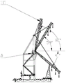
FIG. 1 is a schematic view of the present invention;
FIG. 2 is a schematic view of a guide platform;
FIG. 3 is an enlarged view of FIG. 2-A;
FIG. 4 is a front view of the post;
figure 5 is a front view of the hoisting frame;
FIGS. 6-8 are schematic views of a crane;
FIG. 9 is a partial enlarged view of FIG. 6-A;
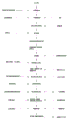
FIG. 10 is a flow chart of the present invention;
a hull body 100; a crane 110; a first secondary vessel 210; a second tug 220; a work anchor 310; a guide frame 410; a spud 420; a leg 430; 411, installing a hoop; a lower anchor ear 412; a hydraulic ram 510; a roller 520; a roller 530; a column 610; hoisting frame 600; a boom 111; a turntable 112; a column 113; a diagonal brace 114; an amplitude variation pulley block 115; a slewing bearing 116; a rest 117.
[ detailed description ] embodiments
In the description of the present invention, it is to be understood that the terms "center", "upper", "lower", "front", "rear", "left", "right", and the like, indicate orientations or positional relationships based on the orientations or positional relationships shown in the drawings, and are only for convenience in describing the present invention and simplifying the description, but do not indicate or imply that the device or element referred to must have a specific orientation, be constructed and operated in a specific orientation, and thus, should not be construed as limiting the present invention. Furthermore, the terms "first" and "second" are used for descriptive purposes only and are not to be construed as indicating or implying relative importance.
In the description of the present invention, it should be noted that, unless otherwise explicitly specified or limited, the terms "mounted," "connected," and "connected" are to be construed broadly, e.g., as meaning either a fixed connection, a removable connection, or an integral connection; can be mechanically or electrically connected; either directly or indirectly through intervening media, or may be interconnected between two elements. The specific meaning of the above terms in the present invention can be understood in specific cases to those skilled in the art. In addition, in the description of the present invention, "a plurality" or "a plurality" means two or more unless otherwise specified.
Referring to fig. 1-10, fig. 1-10 disclose a best embodiment of a method for constructing an offshore wind power single pile foundation and a dedicated vessel:
a construction method of an offshore wind power single-pile foundation comprises the following steps:
construction preparation: various materials and equipment are prepared in place, the manufactured guide frame 410 is placed at the position of a special ship starting support leg, and the positioning pile 420 is hung on the guide frame 410 through a supporting structure.
The specific process is as follows:
(1) collecting and surveying equipment and personnel entering and construction sea area conditions;
(2) compiling an implementation construction organization design, and compiling a special construction technology and a safety scheme;
(3) setting a measurement control point and a measurement signal propagation base station;
(4) the pre-post training and the technology of the building personnel are handed over;
(5) mechanical equipment is overhauled and operated in a test mode;
(6) the lifting appliance, the tool, the safety protection article and the like are configured in place.
Firstly, positioning a special ship: the special ship is accurately positioned to the piling position through the GPS and the anchor mooring ship,
the specific process is as follows:
(1) the special ship is provided with a GPS piling and positioning system, which consists of three parts: a computer terminal and a video display screen (capable of displaying positioning data in real time) which are positioned in the control room, a photoelectric distance measuring instrument and a DV probe which are positioned in the two-layer cabin, and 3 GPS stations (1 GPS for standby) which are positioned on the front deck and the rear deck.
(2) According to the hydrological meteorological data of the wind field sea area, the sea current direction and the falling current direction are known, and the heading orientation of the ship is determined by combining the influence of tidal water and waves.
(3) The position coordinate and the standing position angle of the machine to be constructed are input into the GPS piling and positioning system, and the pile position deviation and the torsion angle deviation can be displayed on a display interface of the positioning system in real time. According to the deviation, the special ship drives to the position of the machine and throws 8 work anchors 310. The special ship shifts in the wind power plant area range and adopts a self-propulsion mode. The special vessel is equipped with 8 anchors (four anchors each in front and rear), each anchor having a mooring line length of 700m, and according to the present engineering situation, the special vessel has a mooring distance (from the side of the vessel) of 500 m.
(4) The anchor chain group consisting of 8 working anchors 310 of the special ship can be monitored by a computer on a driving platform and operated in a centralized way. After 8 work anchors 310 of the special ship are set in place, deviation conditions are displayed through a positioning system, all anchor conditions are adjusted on a driving platform, and the special ship is accurately positioned to a piling position through a mooring and transfer ship.
Secondly, sinking the positioning pile: the spud 420 is lowered by a vibratory hammer, and then the guide frame 410 is hung on the spud 420 by a hanging mechanism.
The concrete process of the third step is as follows:
(1) after the special ship is accurately positioned, 4 positioning piles 420 are sunk in sequence by using a vibration hammer; the guide frame 410 is now still on the dedicated vessel.
(2) After the 4 spuds 420 are sunk in place, the special crane 110 lifts the guide frame 410.
(3) After the guiding frame 410 is lifted to a certain height, the guiding frame 410 is hung on the top of the positioning pile 420 by using a hanging structure. The suspension structure consists of a steel structure hook, finish rolling twisted steel and a nut. Three hooks are arranged on the top of each positioning pile 420, and the weight of each finish rolling threaded steel bar is guaranteed to be evenly stressed through the support of the guide frame 410 by the finish rolling threaded steel bars.
(4) After the platform of the guide frame 410 is leveled, the positioning pile 420 and the guide frame 410 are locked by a steel wedge block, so that a stable and reliable offshore positioning guide platform is formed.
(5) The height of the guiding platform should be considered to be affected by the rising and falling tide, so as to ensure that the special ship deck does not touch the guiding frame 410 at high tide level.
Thirdly, adjusting the guide frame: ensuring that the guide frame 410 is substantially horizontal by adjusting the suspension mechanism;
the specific process is as follows:
and measuring the levelness of the platform of the guide frame 410, and ensuring the basic levelness of the platform of the guide frame 410 by adjusting the suspension length of the finish rolling screw thread.
Fourthly, moving the structural steel pile into: the special boat crane 110 is hooked to erect the structural steel piles, and the structural steel piles are moved into the upper anchor ear 411 and the lower anchor ear 412 of the guide frame 410.
The specific process is as follows:
(1) and finishing the construction of the guide platform 410, berthing one side of the special ship by the pile transporting barge, and hoisting the structural steel pile up and down by the special ship crane 110.
(2) After the structural steel pile is horizontally hoisted to a certain height, the pile transporting barge is driven away from the special ship, the special ship crane 110 continues to hoist the hook, the special ship crane 110 loosens the hoisting point and swings the large arm at the left side, after the structural steel pile is transferred to the bow, the structural steel pile is changed into a vertical state, and after the structural steel pile is erected, the hoisting point is detached.
Fifthly, centering the structural steel pile: after the special ship crane vertically lifts the structural steel pile, the structural steel pile is fed into the upper and lower hoops of the guide frame through the swinging and amplitude variation of the crane boom, the upper hoop 411 and the lower hoop 412 are closed, and the hydraulic jacks 510 positioned on the upper hoop 411 and the lower hoop 412 are ejected out, so that the structural steel pile is positioned at the center of the upper hoop 411 and the lower hoop 412.
Sixthly, sinking the structural steel pile: and (4) falling the hook by the floating crane, and simultaneously measuring the verticality at regular time to enable the structural steel pile to enter mud in a vertical state and sink automatically.
The specific process is as follows:
(1) and a measurer measures the verticality of the steel pile by utilizing a theodolite to sweep the edge, and a field technician adjusts the stroke of the hydraulic ram 510 according to the measurement result to adjust the steel pile to be in a vertical state.
(2) After the structural steel pile is straightened, the special ship crane 110 slowly loosens the hook, the structural steel pile begins to go into mud by the dead weight, and in the mud process is gone into by the dead weight, every time sinking a certain distance, stops loosening the hook, measures and rechecks the structural steel pile straightness that hangs down, if the structural steel pile takes place to incline, adjusts the structural steel pile straightness that hangs down through staple bolt hydro-cylinder 510 and is vertical state, and the vertical rear of structural steel pile can continue to sink.
(3) After the steel pile is driven into the mud by self weight, the special ship crane 110 is unhooked.
Seventhly, pile sinking preparation: and measuring the verticality of the structural steel pile, carrying out geological analysis, finding out the stratum where pile slipping easily occurs, and designing a pile slipping scheme.
The specific process is as follows:
(1) before pile sinking construction, pile driving analysis is carried out on the pile sinking condition by combining with early-stage exploration and design data and utilizing special pile driving analysis software GRLWEAP, and the stratum possibly subjected to pile slipping is found out according to the pile sinking energy and the penetration data, so that prevention is carried out in advance.
(2) After the hydraulic hammer is aligned to the pile top by the crane 110, the hoisting steel wire rope is lowered to the top of the hydraulic hammer, the shackle is horizontally laid, and then the steel wire rope is continuously lowered by about 10cm, so that the hook is stopped to be loosened, and the impact on the crane 110 caused by sudden pile slipping is prevented. In the subsequent pile sinking process, the same rope loosening amount of the crane 110 is ensured. The aim of loosening and loosening is achieved as little as possible, and the crane 110 can hoist the hydraulic hammer as soon as possible under the condition of pile slipping, so that the impact on the crane 110 under the condition of pile slipping is reduced.
(3) The hydraulic hammer is provided with two braking sensors for preventing the hammer from being knocked empty, one braking sensor is positioned at the hammer top of the hydraulic hammer, and when the hammer top shackle is positioned between a vertical state and a 45-degree angle, the sensors can sense and send braking signals and automatically stop hammering; that is, when pile slipping occurs, the hammering operation is automatically stopped before the hydraulic hammer is lifted. One is positioned above the hydraulic hammer mill, when the whole weight of the hydraulic hammer falls on the pile top, the mill of the hydraulic hammer can be jacked upwards, and the sensor can sense a signal to carry out hammering; when slipping occurs, the steel wire rope of the hanging hammer is forced, the weight of the hydraulic hammer does not completely fall on the top of the pile, and the sensor sends a signal to automatically stop hammering operation.
(4) When the pile sinking is initially hammered, pile slipping is most likely to occur, so the initial striking energy of the pile sinking is set to the minimum energy of the hydraulic hammer. Pile sinking is started by single click, namely, after one hammer is hammered, the hammer is stopped to observe the penetration degree of the steel pile. And continuously clicking 3-5 hammers to observe the penetration condition of the steel pile, and if the penetration is less than 5 cm/single hammer, continuously punching the pile, otherwise, continuously clicking.
(5) In the pile sinking process, when the pile sinking is close to the stratum with the possibility of pile slipping, the striking energy and the hammering speed are reduced in advance to prevent the possible pile slipping.
(6) In the pile sinking process, the hammering speed and energy are adjusted in real time according to the penetration degree condition, and the penetration degree of the pile sinking is controlled to be between 1cm and 2 cm. Most of the time, too much penetration is a precursor to pile slipping. When the penetration is larger, the hammering energy is reduced, the hammering speed is reduced, even the single-click can be carried out with the minimum energy, and the pile slipping is prevented.
Eighthly, sinking the structural steel pile: and (5) inserting and driving the structural steel pile to the designed elevation by using a hydraulic hammer.
The nine specific processes are as follows:
the steel pipe pile sinking takes elevation control as a standard, and the penetration degree is used as check. All piles should be sunk to the designed elevation, but when one of the following conditions is met, pile sinking can be stopped, and pile sinking records are made and notified to a field supervisor:
(1) the pile top reaches the designed elevation, and the average penetration of the last 6 continuous 25cm is not more than 20 mm.
(2) The pile top does not reach the designed elevation, the height of the pile top is less than 1.5m, and the average penetration of the pile top which is hit by 50cm with the maximum hammering energy is still less than 3 mm.
(3) The pile top does not reach the designed elevation, the pile top is over 1.5m, but the total hammering number exceeds 7000 strokes, or the last 1m piling hammering number exceeds 1000 strokes according to the maximum hammering force.
When one of the following conditions is met, pile sinking is stopped immediately, pile sinking records are notified to a site manager and an owner in time, the site manager and the owner contact with a designer, and corresponding measures are taken in a discussion:
(1) the pile top reaches the designed elevation, and finally the average penetration of 25cm exceeds 20 mm.
(2) The pile top does not reach the designed elevation, the height of the pile top is more than 1.5m, and the average penetration of the pile top which is hit by 50cm with the maximum hammering energy is still less than 3 mm.
(3) The pile body is seriously deviated and inclined.
Ninthly, pile sinking measurement control: and the allowable deviation of the structural steel pile is ensured to meet the process requirement.
In this embodiment, the absolute position deviation is 500mm, the elevation deviation is 50mm, and the inclination deviation of the pile axis is less than or equal to 3 ‰
The specific process of the step ten is as follows:
1. and (3) measuring and controlling the absolute position of the steel pile:
(1) and a GPS pile driving positioning system is used for accurate positioning, so that the deviation between the center coordinate of the hoop of the guide platform and the center coordinate of the construction steel pile is within an error range.
(2) After the construction of the guide frame 410 platform is completed, the deviation between the hoop center and the pile position center of the guide platform is measured by a GPS, and the plane position of the steel pile is further adjusted by a jack when the steel pile is aligned and sunk, so that the deviation of the plane position of the steel pile is ensured to be less than 50 cm.
2. Pile top elevation measurement control:
(1) after the construction of the guide platform is completed, the measuring personnel measure the elevation of the lower guide platform through the GPS and make a record.
(2) In the pile sinking process, when the elevation of the pile top is close to the design elevation through the elevation of the platform in an visual inspection mode, the hammer is informed to stop and the elevation of the pile top at the moment is measured. And pre-judging the required hammering number according to the measurement result and the hammering penetration condition.
(3) And continuously hammering the pile, after hammering for a certain hammer number, informing to stop the hammer and measuring the elevation of the pile top at the moment. And pre-judging the required hammering number according to the measurement result and the hammering penetration condition.
(4) And (4) repeating the process (3) until the design requirement elevation is reached.
During elevation measurement control, elevation control reference given by a design drawing is required to be clear, and the uniformity of an elevation system is ensured.
3. And (3) measuring and controlling the verticality of the steel pile:
(1) before the steel pile is driven into the mud, the verticality of the steel pile is measured by a theodolite, and the vertical state of the steel pile is adjusted through a hydraulic jack 510 on the guide platform. The theodolite is arranged on the positioning guide platform, and the two theodolite are arranged in the direction of 90 degrees. And (3) suspending sinking every 50-100 cm in the self-weight mud entering process of the steel pile, and measuring and adjusting the verticality of the steel pile.
(2) Before pile sinking construction, the measuring platform is lifted to the pile top, and the levelness of the pile top flange before pile sinking is accurately measured. And the levelness of the pile top flange is accurately adjusted according to the measurement result, so that the horizontal height difference of the pile top flange is within 3 mm.
(3) In the process of hammering pile sinking, the levelness condition of the flange at the top of the steel pile can be monitored in real time through the high-precision double-shaft inclination angle measuring instrument on the hydraulic hammer. In the pile sinking process, the sinking is suspended every 50-200 cm, the perpendicularity of the steel pile is adjusted according to the measurement condition, and the perpendicularity of the steel pile is guaranteed to be within the range of the design requirement. Meanwhile, the verticality is measured on the guide platform by erecting the theodolite, and the results of the two measurement methods are checked and compared with each other, so that the measurement result is correct, and the levelness deviation of the pile top flange is ensured to be within an allowable range.
More specifically, a high precision dual axis inclinometer is mounted on a hydraulic hammer that measures pile top levelness through a self height sensitivity sensor and associated chip. When the hammer is stopped for measurement, the built-in radio station sends sensor data to a remote computer, and the computer analyzes received radio station signals through professional measurement software, so that the pile inclination angle, the pile top slope ratio, the pile top offset and the like can be calculated in real time. The gradient measuring error of the high-precision double-shaft inclination angle measuring instrument can reach 0.1 per mill. Before the first measurement, the dual-axis inclinometer needs to be calibrated.
Dismantling a guide platform: the special boat crane 110 lifts the guide frame 410 and places it on the special boat deck, vibrates the hammer to the top of the spud 420, pulls the spud 420 out of the sea bed and hangs it on the guide frame 410 through the support structure.
The concrete process of the eleventh step is as follows:
after the pile is sunk to the designed elevation, the hydraulic hammer and the pile feeder are hoisted and returned to the original position. The special purpose vessel crane 110 begins to remove the guide platform.
(1) Removing the locking wedge between the guide frame 410 and the spud 420;
(2) the hoisting guide frame 410 has a certain height, so that the suspension structure is not stressed, and the suspension structure of the pile top of the positioning pile 420 is removed;
(3) after the suspension structure is removed, the lifting guide frame 410 of the special boat crane 110 is dropped onto the special boat deck fixing position.
(4) The special marine crane 110 lifts the vibratory hammer to the top of the spud 420, sequentially pulls out 4 spuds 420 from the seabed and hangs the spud 420 on the guide frame 410.
In this embodiment, still need hoist and mount additional structure to structural steel pile.
The specific process is as follows:
(1) after the special ship crane 110 hoists the muffs for a certain tonnage, the locking device of the muffs on the barge is released. After the locking device is released, the sleeve cage is lifted from the barge to a certain height and is placed above the pile top after pile sinking is completed.
(2) The special boat crane 110 is aligned and slowly lowered, and the sleeve cage structure is sleeved outside the steel pile. And slowly rotating the angle of the sleeve cage in a cable tying wind mode according to marks on the steel piles and the sleeve cage before leaving a factory, so that the marks are overlapped and are installed in an aligned mode.
(3) After the alignment of the lantern structure is completed, the special ship crane 110 loosens the hook to be installed in place.
(4) The special boat crane 110 lifts the inner platform from the barge for installation. And similarly, carrying out alignment installation according to a marking line made before delivery. After the platform ring plate in the stake is transferred to the counterpoint, special ship loop wheel machine 110 tears the hook open, goes up interior platform fastening screw, and connect the earth connection.
A ship special for offshore wind power single-pile foundation construction comprises a ship body 100. In this embodiment, the hull body 100 is an open-top ship, and the open-top ship is provided with a first secondary ship 210 and a second secondary ship 220, and a passage is formed between the first secondary ship 210 and the second secondary ship 220.
In this embodiment, the crane 100 includes a boom 111, a turntable 112, a column 113, an inclined strut 114, an amplitude pulley block 115 and a slewing bearing 116, the column 113 is fixedly disposed on a crane frame 600 and vertically disposed, one end of the inclined strut 114 is fixedly connected to the top of the column 113, the other end of the inclined strut 114 is fixed to two rear corners of the top of the crane frame, the turntable 112 is connected to the column 113 through a bolt connection with the slewing bearing 116, the slewing bearing 116 is connected to a flange bolt welded to the lower portion of the column 113, one end of the boom 111 is pivotally connected to the turntable 112 through a pin shaft, the amplitude pulley block 115 is disposed between the other end of the boom 111 and the top of the column 113, and the boom 111 rotates up and down through the amplitude pulley block 115. In this embodiment, the deck is further provided with a shelf 117, and when the crane is not used, the crane arm 111 is stored by placing the crane arm 111 on the shelf 117 of the deck surface through the luffing pulley block 115. The slewing bearing 116 is composed of a motor, a brake, a planetary gear reducer and a large pinion, an offset flange is adopted for positioning between the small pinion and the large pinion, the slewing bearing is of a three-row roller type with an external gear and capable of preventing water, and the reducer is installed on a stand column and arranged in four corners.
Specifically, a piling and positioning system, an anchor chain group, a guide platform and a crane 110 are arranged on the hull body 100; in this embodiment, for better construction, the guiding platform and the crane 110 are erected on the first secondary vessel 210 and the second secondary vessel 220, and the guiding platform is partially immersed in river water and towed.
More specifically, the guide platform includes a guide frame 410 and 4 spuds 420, the spuds 420 are evenly arranged in the circumferential direction of the guide frame 410, and the guide frame 410 located on the opposite position of the spuds 420 is provided with a support leg 430 for erecting the first secondary vessel 210 and the second secondary vessel 220. In the embodiment, the length of the positioning pile is 50 meters, the diameter is 2.42m, and the plate thickness is 25 mm; four positioning piles are arranged at four corners of the guide frame. The legs 430 are used for fixedly connecting with the first secondary vessel 210 and the second secondary vessel 220, so that the guide frame 410 is erected on the special vessel and moves along with the movement of the special vessel; in this embodiment, the positioning pile 420 is suspended on the guiding frame 410 through the supporting mechanism, and during operation, the crane 110 lifts the positioning column, then the corresponding supporting mechanism is detached, and then the positioning column is sunk through the vibration hammer. After the pile is driven, the crane 110 lifts the positioning column, and the positioning column is pulled up by the vibration hammer, and then is hung on the guide frame 410 by the supporting mechanism. The problem that the guide frame 410 needs to be plugged and pulled for multiple times is solved, and the productivity of an enterprise is improved.
More specifically, the guide frame 410 includes an upper hoop 411 and a lower hoop 412, and in this embodiment, the height distance between the upper hoop 411 and the lower hoop 412 is 10.5 meters. The effective working diameter of the upper and lower anchor ears is 5.5-7.2 m. The upper hoop 411 and the lower hoop 412 are respectively provided with 4 hydraulic jacks 510, the end parts of the hydraulic jacks 510 are provided with rollers 520, and the rollers 520 are in rolling connection with the end parts of the hydraulic jacks 510 through rollers 530. During working, the perpendicularity of the steel pile is constantly maintained through the hydraulic jacks 510 of the upper anchor ear 411 and the lower anchor ear 412; in the embodiment, the thrust of the single hydraulic ram 510 is 150t, the roller 520 is a rubber wheel, and paint on the surface of the steel pile can be effectively protected from being damaged in the construction process.
More specifically, the anchor chain groups are provided at both ends of the hull body 100; in this embodiment, the anchor chain set includes 8 work anchors 310, the first secondary vessel 210 and the second secondary vessel 220 are provided with a bow and a stern, the bow of the first secondary vessel 210 and the bow of the second secondary vessel 220 are provided with 2 work anchors 310, and the stern of the first secondary vessel 210 and the second secondary vessel 220 are provided with 2 work anchors 310. In this embodiment, the length of the anchor line of each work anchor is 700m, and the anchoring distance of the special ship is 500m according to the engineering condition.
More specifically, pile positioning system includes the computer terminal that is located the control room, is located the photoelectric distance measuring instrument of second deck cabin room, DV probe and sets up 3 GPS survey stations on preceding back deck, GPS survey station, photoelectric distance measuring instrument and DV probe all are connected with the computer terminal electricity. By inputting the position marking and the standing position angle of the machine to be constructed at the computer terminal, the computer terminal can display the pile position deviation and the torsion angle deviation in real time, the special ship drives to the position of the machine position and throws 8 working anchors 310 according to the deviation condition, and an anchor chain group consisting of 8 working anchors 310 of the special ship can be operated in a centralized way through the computer terminal. After 8 work anchors 310 of the special ship are set in place, deviation conditions are displayed through a GPS (global positioning system) survey station, each anchor condition is adjusted at a computer terminal, and the special ship is accurately positioned to a piling position through the anchor mooring and transfer ship.
The pile positioning system and the anchor chain set are electrically connected with a control system on the hull body 100, and the rotation radius of the crane 110 is larger than the distance between the guide platform and the crane 110. In this embodiment, the maximum hoisting capacity of the crane 110 is 1800 tons, which meets the requirement of daily work. In this embodiment, the vertical rotation angle of the crane is 80 ° at the maximum upward rotation and 41 ° at the maximum downward rotation, based on the horizontal plane. The maximum left-right rotation is 105 degrees by taking the centerline of the hull body 100 to be 45 degrees towards the right as a reference
Finally, it should be noted that: although the present invention has been described in detail with reference to the foregoing embodiments, it will be apparent to those skilled in the art that changes may be made in the embodiments and/or equivalents thereof without departing from the spirit and scope of the utility model. Any modification, equivalent replacement, or improvement made within the spirit and principle of the present invention should be included in the protection scope of the present invention.
Claims (10)
1. A construction method of an offshore wind power single-pile foundation is characterized by comprising the following steps: the method comprises the following steps:
firstly, construction preparation: the manufactured guide frame is placed at the position of the special ship opening support leg, and the positioning pile is hung on the guide frame through the supporting structure;
secondly, positioning of the special ship: the special ship is accurately positioned to a piling position through a GPS and a mooring anchor transfer ship;
thirdly, sinking the positioning pile: the positioning pile is hammered by a vibration hammer and inserted into the seabed, then the guide frame is lifted by the special ship crane and hung on the positioning pile through the hanging mechanism, and the guide frame is separated from the special ship body and fixed above the sea surface;
fourthly, adjusting the guide frame: the guide frame is ensured to be basically horizontal by adjusting the suspension mechanism;
fifthly, moving the structural steel pile into: the special ship crane is hooked, the structural steel pile is erected, and the structural steel pile is moved into the upper and lower hoops of the guide frame;
sixthly, centering the structural steel pile: closing the upper and lower hoops, and ejecting out the hydraulic jacks positioned on the upper and lower hoops to ensure that the structural steel pile is positioned at the center of the upper and lower hoops;
seventhly, self-sinking of the structural steel pile: the special ship crane slowly drops the hook, and simultaneously measures in real time and adjusts the verticality of the structural steel pile through the hoop oil cylinder, so that the structural steel pile enters mud in a vertical state and sinks automatically;
eighthly, pile sinking preparation: carrying out geological analysis by using special software, finding out a stratum which is easy to slip a pile and designing a pile slipping control scheme;
ninthly, sinking the structural steel pile: inserting and driving the structural steel pile to a designed elevation by using a hydraulic hammer;
tenthly, pile sinking measurement control: ensuring that the structural steel pile meets the technological requirements;
eleven, dismantling a guide platform: the special ship crane hangs the guide frame and loosens the hanging device, the guide frame is placed at the position of the support leg of the special ship along the positioning pile, and the vibration hammer pulls out the positioning pile from the seabed and hangs the positioning pile on the guide frame through the supporting structure;
twelve, hoisting accessory structures: and (3) hoisting auxiliary structures such as a hoisting sleeve cage of the special ship crane, completing hoisting, and moving the ship to the next machine position for pile sinking construction.
2. The offshore wind power single pile foundation construction method according to claim 1, characterized in that: the concrete process of the third step is as follows:
1) the special ship is accurately positioned, 4 positioning piles are sequentially sunk by using a vibration hammer, and the guide frame still falls on the special ship;
2) after the 4 positioning piles sink in place, a crane on the special ship lifts the guide frame and lifts the guide frame to a certain height;
3) hanging a guide frame on the positioning pile by using a suspension structure;
4) and the positioning pile and the guide frame are locked through a steel wedge block.
3. The offshore wind power single pile foundation construction method according to claim 1, characterized in that: the concrete process of the step eight is as follows:
1) pile driving analysis is carried out on the pile sinking condition by combining early-stage exploration design data and combining professional pile driving analysis software GRLWEAP, and the stratum where pile slipping is likely to occur is found out according to the pile sinking energy and the penetration degree, so that defense is carried out in advance.
4. The offshore wind power single pile foundation construction method according to claim 1, characterized in that: the concrete process of the step five is as follows:
1) a special ship crane lifts the steel pile of the structure to lift the steel pile up and down at one side of the special ship for pile transporting barge berthing;
2) after the structural steel pile is horizontally hoisted to a certain height, the pile transporting barge drives away from the special ship, the special ship crane continues to hook, the special ship crane loosens the hoisting point while swinging the large arm to the left, the structural steel pile is changed into a vertical state after the structural steel pile is transferred to the bow of the ship, and the hoisting point is detached after the structural steel pile is erected;
3) after the special ship crane vertically hoists the structural steel pile, feeding the structural steel pile into the upper and lower hoops of the guide frame through the swinging and amplitude variation of the crane boom, closing the upper and lower hoops, ejecting out the hydraulic ram, and fixing the structural steel pile at the central positions of the upper and lower hoops;
4) measuring the perpendicularity of the structural steel pile by using a grazing of a theodolite, adjusting the stroke of a hydraulic jack according to the measuring result, and adjusting the structural steel pile to be in a vertical state;
5) after the structural steel pile is straightened, the special ship crane slowly looses the hook, the structural steel pile starts to enter the mud in a self-weight mode, the hook loosening is stopped when the structural steel pile sinks for a certain distance in the self-weight mud entering process, the verticality of the structural steel pile is rechecked, if the structural steel pile inclines, the verticality of the structural steel pile is adjusted to be in a vertical state through the hoop oil cylinder, and the structural steel pile can continue to sink vertically behind the structural steel pile;
6) after the structural steel pile is driven into the mud by self weight, the special ship crane is unhooked.
5. The offshore wind power single pile foundation construction method according to claim 1, characterized in that: and the pile sinking deviation of the step ten comprises absolute position deviation, elevation deviation and pile axis inclination deviation.
6. The offshore wind power single pile foundation construction method according to claim 5, characterized in that: the absolute position deviation is 500mm, the elevation deviation is 50mm, and the inclination deviation of the pile axis is less than or equal to 3 per thousand.
7. The offshore wind power single pile foundation construction method according to claim 5, characterized in that: the specific measurement process of the absolute position deviation is as follows:
1) accurately positioning by using a GPS piling and positioning system to ensure that the deviation between the central coordinates of the upper and lower anchor ears and the central coordinate of the structural steel pile is within an error range;
2) after the construction of the guide frame is completed, the deviation between the centers of the upper and lower anchor ears and the center of the structural steel pile position is measured by a GPS, and the plane position of the structural steel pile is further adjusted by a jack when the structural steel pile is aligned and sunk, so that the deviation of the plane position of the steel pile is ensured to be less than 50 cm.
8. The offshore wind power single pile foundation construction method according to claim 5, characterized in that: the elevation deviation measuring process comprises the following specific steps:
1) after the construction of the guide frame is completed, measuring staff measure the elevation of the lower anchor ear through a GPS and make a record;
2) in the pile sinking process, through the elevation of the guide frame, when the elevation of the pile top is visually measured to be close to the designed elevation, stopping the hammer and measuring the elevation of the pile top at the moment, and pre-judging the required hammering number according to the measurement result and the hammering penetration degree;
3) continuously hammering the pile, stopping hammering the pile for a certain number of hammers, measuring the elevation of the pile top at the moment, and pre-judging the required number of hammering according to the measurement result and the hammering penetration condition;
4) and repeating the process 3 until the design requirement elevation is reached.
9. The offshore wind power single pile foundation construction method according to claim 5, characterized in that: the concrete measuring process of the inclination deviation of the pile axis is as follows:
1) before the structural steel pile is driven into the mud, the verticality of the structural steel pile is measured by using a theodolite, the vertical state of the structural steel pile is adjusted by using a hydraulic jack of a guide frame, the theodolite is arranged on the guide frame, the two theodolite are arranged in a 90-degree direction, the structural steel pile is suspended and sunk every 50-100 cm in the self-weight mud driving process, and the verticality of the structural steel pile is measured and adjusted;
2) before pile sinking construction, hoisting a measuring guide frame to the pile top, accurately measuring the levelness of a pile top flange before pile sinking, and accurately adjusting the levelness of the pile top flange according to a measuring result to enable the horizontal height difference of the pile top flange to be within 3 mm;
3) in the hammering pile sinking process, the high-precision double-shaft inclination angle measuring instrument on the hydraulic hammer can monitor the levelness condition of the flange at the top of the steel pile in real time, in the pile sinking process, the steel pile is suspended and sunk every 50-200 cm, the verticality of the structural steel pile is adjusted according to the measuring condition, the verticality of the structural steel pile is guaranteed to be within the range of design requirements, meanwhile, the theodolite is erected to measure the verticality on the guide frame, the results of the two measuring methods are checked and compared with each other, the measuring result is guaranteed to be correct, and the levelness deviation of the flange at the top of the pile is guaranteed to be within the allowable range.
10. A marine wind-power single pile foundation construction special-purpose ship which characterized in that: including hull body (100), be equipped with pile positioning system, anchor chain group, guide platform, crane boom (600), pile hammer system, loop wheel machine (110) and hydraulic system and electrical system on hull body (100), crane boom (600) major structure is box girder truss structure, and crane boom (600) lower part is passed through sill pillar, bracing and lower link and is connected with hull body, and the loop wheel machine sets up in the crane boom top, guide platform erects on hull body (100), on hull body deck is arranged in to the pile hammer system, anchor chain group sets up the both ends at hull body (100), pile positioning system and anchor chain group all are connected with the control system electricity on pile driving hull body (100), loop wheel machine (110) radius of rotation is greater than the distance of guide platform and loop wheel machine (110).
Priority Applications (1)
| Application Number | Priority Date | Filing Date | Title |
|---|---|---|---|
| CN202111516393.8A CN114319356A (en) | 2021-12-09 | 2021-12-09 | Offshore wind power single-pile foundation construction method and special ship |
Applications Claiming Priority (1)
| Application Number | Priority Date | Filing Date | Title |
|---|---|---|---|
| CN202111516393.8A CN114319356A (en) | 2021-12-09 | 2021-12-09 | Offshore wind power single-pile foundation construction method and special ship |
Publications (1)
| Publication Number | Publication Date |
|---|---|
| CN114319356A true CN114319356A (en) | 2022-04-12 |
Family
ID=81050506
Family Applications (1)
| Application Number | Title | Priority Date | Filing Date |
|---|---|---|---|
| CN202111516393.8A Pending CN114319356A (en) | 2021-12-09 | 2021-12-09 | Offshore wind power single-pile foundation construction method and special ship |
Country Status (1)
| Country | Link |
|---|---|
| CN (1) | CN114319356A (en) |
Cited By (3)
| Publication number | Priority date | Publication date | Assignee | Title |
|---|---|---|---|---|
| CN114872829A (en) * | 2022-04-21 | 2022-08-09 | 中交第四航务工程勘察设计院有限公司 | Anchoring construction method and system for operation ship and steel pile driving ship |
| CN117488800A (en) * | 2024-01-02 | 2024-02-02 | 中国建筑第六工程局有限公司 | Deep-sea steel pipe pile separation recovery device and construction method |
| CN117488800B (en) * | 2024-01-02 | 2024-05-14 | 中国建筑第六工程局有限公司 | Deep-sea steel pipe pile separation recovery device and construction method |
-
2021
- 2021-12-09 CN CN202111516393.8A patent/CN114319356A/en active Pending
Cited By (3)
| Publication number | Priority date | Publication date | Assignee | Title |
|---|---|---|---|---|
| CN114872829A (en) * | 2022-04-21 | 2022-08-09 | 中交第四航务工程勘察设计院有限公司 | Anchoring construction method and system for operation ship and steel pile driving ship |
| CN117488800A (en) * | 2024-01-02 | 2024-02-02 | 中国建筑第六工程局有限公司 | Deep-sea steel pipe pile separation recovery device and construction method |
| CN117488800B (en) * | 2024-01-02 | 2024-05-14 | 中国建筑第六工程局有限公司 | Deep-sea steel pipe pile separation recovery device and construction method |
Similar Documents
| Publication | Publication Date | Title |
|---|---|---|
| CN109629568A (en) | The process for sinking of the steady stake platform of offshore wind farm jacket foundation steel pipe pile floating | |
| CN108842806B (en) | Construction process of offshore wind power foundation non-rock-socketed single pile | |
| CN107152027A (en) | Offshore wind farm multi-column pier foundation pile sinking construction method and special leading truck | |
| CN109853567B (en) | Pile sinking method for offshore wind power rock-socketed steel pipe pile | |
| CN105464117A (en) | Rotary-type overwater piling guide frame and piling process for overwater pile group foundations | |
| CN108571425B (en) | Pile foundation cap foundation of offshore wind turbine generator set and construction method thereof | |
| CN102328732A (en) | Offshore pile driving, pile pressing and installing united engineering ship | |
| CN113006075B (en) | Steel pipe pile implanting method for implanting rock-socketed pile foundation construction | |
| CN105672314A (en) | Method for constructing steel pipe upright pile through semi-reversed-construction method | |
| CN106812144A (en) | Double-wall steel cofferdam construction method | |
| CN114673153A (en) | Construction method of complex stratum overlength large-diameter pile foundation casing structure | |
| CN103422486B (en) | Shipborne truss combined in-situ testing platform | |
| CN114319356A (en) | Offshore wind power single-pile foundation construction method and special ship | |
| CN110055984B (en) | Lowering construction method for double-wall deformed steel cofferdam | |
| JP5813109B2 (en) | Surface-projecting reusable underwater template for installing one or more underwater struts or piles | |
| CN113897959A (en) | Underwater positioning guide frame for offshore wind power foundation pile sinking and pile sinking construction method | |
| CN216615834U (en) | Marine wind-power single-pile foundation construction special-purpose ship | |
| CN208792357U (en) | A kind of control platform for the construction of marine jacket-type blower foundation | |
| CN217460571U (en) | Precise positioning floating construction platform for deep reservoir area | |
| GB1587334A (en) | Bridge structures | |
| CN210737541U (en) | Positioning device for lowering protective cylinder of underwater cast-in-place pile | |
| CN109736285B (en) | Automatic monitoring system for offshore remote underwater foundation settlement | |
| CN112095606A (en) | Float bowl leveling pile gripper | |
| CN220433648U (en) | Multifunctional pile stabilizing platform | |
| CN219343190U (en) | Shipborne three-layer telescopic movable guide frame |
Legal Events
| Date | Code | Title | Description |
|---|---|---|---|
| PB01 | Publication | ||
| PB01 | Publication | ||
| SE01 | Entry into force of request for substantive examination | ||
| SE01 | Entry into force of request for substantive examination |